| Egg Crasher Video Game |
| ECE 5760 |
| Spring 2014 |
| Team Member: Zhenxuan Qiu, Jiachen Hu, Jianglu Xu(Georald) |
|
Project Video:
|
| Contents |
| 1 | Introduction | |
| 1.1 | Brief Summary | |
| 2 | High Level Design | |
| 2.1 | Project Idea and Game Rationale | |
| 2.2 | Logic Structure | |
| 2.3 | Choice of Programming Method | |
|
3
|
Hardware Design | |
| 3.1 | M4K | |
| 3.2 | VGA controller | |
| 3.3 | Camera Input | |
| 4 | Program Design | |
| 4.1 | State Machine | |
| 4.2 | Pen Detection | |
| 4.3 | Draw Tracking | |
| 4.4 | Circle Accuracy Detection | |
| 4.5 | Object Falling Motion and Hit Detection | |
| 4.6 | Other Programming Details | |
| 5 | Results of Design | |
| 5.1 | Game Outcome | |
| 5.2 | Speed of Execution | |
| 5.3 | Problems | |
| 6 | Conclusions | |
| 7 | Appendix | |
| 7.1 | Commented Program Listing |
| 1 | Introduction |
| 1.1 | Brief Summary |
|
Our project is to do an “egg crasher” video game. It is a single-player video game based on real-time edge and color detection. The design is built on a Cyclone II FPGA on an Altera DE2 development board, and the game is displayed on a VGA monitor. The system detects the motion of the player’s hand in the vertical direction through an HTC 231x CCD camera. The game requires the player to draw a circle in front of the camera. It will then detect whether the circle is round or not. The circle is given a damage according to the player’s drawing, then the game drops this circle to hit a virtual egg in the bottom of the display. The better the circle is, the higher the score player get as well as the extent that the egg is smashed. |
| 2 | High Level Design |
| 2.1 | Project Idea and Game Rationale |
|
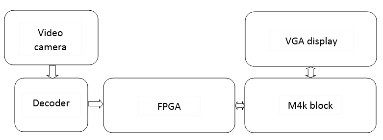
Our idea came from a touch sensing cellphone game. In that game the player needs to draw several graphs on the screen to form the player’s own army, so that the player is able to fight against the PC’s army. We think the detection of graph is very useful in many cases and it is also very interesting, so we decided to design the video game of “egg crasher” to smash the egg by player-defined circles. |
|
|
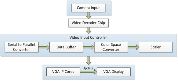
| Figure 1: High Level Hardware Block Diagram |
|
In our game, the player needs to draw a circle as well as he can to smash the egg on the screen. Whether the circle is drawn well enough is directly related to its damage to the egg – the better the circle is, more damage it has to the egg. To implement such a game we need a video camera to detect the player’s finger or a pen, and we need to code a control program on the FPGA to conduct the whole game and a VGA screen to display the game. The high-level hardware block diagram is shown in Figure 1. |
| 2.2 | Logic Structure |
|
The logic structure of our game is described as follows. First the player needs to draw a circle which is detected by FPGA program in several seconds, and a count-down timer will remind the player of the time. At the same time the drawn circle will be recorded and displayed on the screen as the “egg crasher”. After that the drawn circle will be checked by the program whether it is a good circle, then its damage will be decided according to the check result. The checking process is done quickly, and then the circle should fall down. In our game not every circle will hit the only egg on the screen – the circle will fall down from the place it is drawn so the player had better to carefully draw at the right place. If the circle fall down and hit the egg in the end, the egg may or may not be broken based on the damage of the circle. The degree of the egg falling apart is dependent on the damage, too. |
| 2.3 | Choice of Programming Method |
|
We decided to use Verilog HDL hardware programing for this video game. Software coding based on NIOS system is easier to implement and requires little effort on memory clock handling, but it is slower than hardware programming. In the opposite way, hardware programming of this game requires us to carefully handle clock signals of memory and other hardware modules, yet the whole game will speed up compared to a software game. Since we value processing speed more than the ease of implementation, we chose to implement our game design purely by Verilog HDL. |
| 3 | Hardware Design |
| 3.1 | M4K |
|
The dual port M4K is implemented in the module called VGA_Buffer.v which instantiated the module called altsyncram. It is a parameterizable IP(intellectual property) block provided by Altera. By configuring the parameter operation_mode to "BIDIR_DUAL_PORT" and ram_block_type parameter to “M4K”, we instantiate a dual-port M4K block. The address is 19bits long and each address only stores one bit, which is the state for each pixel. The address is the combination of the X coordinate and Y coordinate of the pixel on the screen, {Coord_X[9:0],Coord_Y[8:0]}. Port A is used to update memory for VGA display. The data and address comes from the state machine. Port B only receives the read data request that comes from the VGA controller and send the state bit for display. |
| 3.2 | VGA controller |
| The code for VGA controller is provided by Professor Bruce Land. It is slightly changed from the DE2 default design example. We directly connect it to our M4K memory to get the data after providing the 19bits address of the memory as display. A reset delay module is used to make sure each time the VGA is reset, all the data can be cleared. A PLL module is also instantiated to generate VGA_CTRL_CLK, AUD_CTRL_CLK and VGA_CLK which are used to drive VGA control module, audio codec chip, and VGA separately to eliminate the possible phase shift to make the display more stable. |
| 3.3 | Camera Input |
|
The code for camera input module is also provided by Professor Bruce Land. The video input controller provides a simple interface to the video decoder chip present on the DE2 board. The video decoder chip, as connected on the DE2 board, accepts the composite video input through the Video-In jack on the DE2 board. The controller handles the data transmission and processing which is necessary to obtain the picture data in a simple format. The chip configuration is handled by the separate configuration module, which must be instantiated when using the video input controller. |
|
For our project, the clock used for video input is 27MHz. We also modify the color space converter module to convert the color from YUV 4:2:2 to YUV 4:4:4 and also from YCbCr 8-bit to RGB-10 bit. Since we don’t need mirror effect for our display, we need to comment out the Mirror_Col module in the code. Below (Figure 2) is the diagram showing the video signal path in our camera input module.
|
| 4 | Program Design |
| 4.1 | State Machine |
|
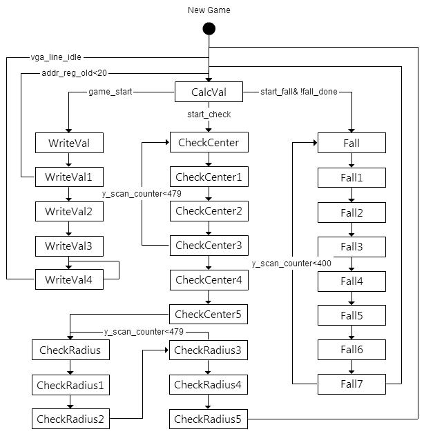
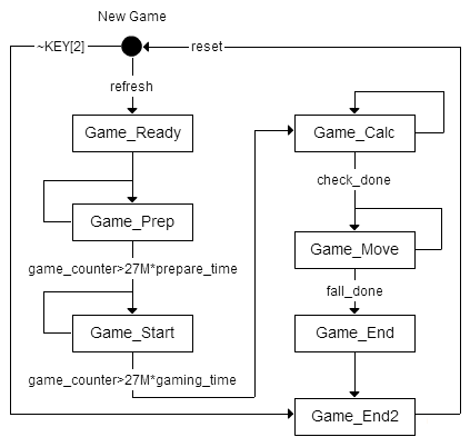
There are two state machines used in our game. One is the main state machine that implements the detection, memory writing and tracking, circle accuracy check and object falling function. Another state machine is a game logic FSM that implements the game procedure functions, i.e. count-down timer for game preparation and circle drawing, damage calculation, egg life calculation, and ending game logic. These states together form a basic game engine for our project. Two FSM are shown in Figure 3 and Figure 4 respectively. The program details of our game can be organized in four main logic parts: color detection, circle drawing, circle accuracy detection, and object falling motion programming. Each part follows the design for test idea during the implementation. We fully tested each logic parts by using LED lights and timing diagrams, and then we put all of them together to form the whole game. Those four parts are described in detail one by one.
|
| 4.2 | Pen Detection |
|
Object detection and tracking is the most basic but one of the most important parts in our game implementation. We used color detection because we think color detection is an easy and reliable way to detect the player’s drawing. Although its detection result may not be as reliable as motion detection result, it is much easier than motion detection processing in terms of implementation, and the reliability of color detection is good enough for our video game. It is a more efficient implementation method in our video game case. For color detection, we can detect the YUV values or detect the RGB values. In order to make our detection more reliable we chose to detect the YUV values, which are recorded and converted by the video camera hardware modules. Since the green color is the easiest color that can be detected, we designed a draw pen on top of which a small piece of green paper is fixed. First we set a threshold to distinguish the green color from other colors. If the detected value is in our defined threshold range, it is the wanted green color. The threshold value range is not fixed, because different video cameras record the world in slightly different data values. So each time we use a different video camera, we should adjust the threshold slightly to make the green-color detection reliable.
We only want to detect the piece of green paper on the pen and ignore other green objects in the environment, so we moved every green objects out of the sight of video game. However the video camera is still able to detect the green colors from the environment due to several light effects, so we designed a way to filter unwanted green colors when doing color detection. When detecting green colors, we would check whether the green area detected is large enough. Since the only green color thing is the draw pen top, we detect the draw pen by checking whether the detected consecutive green-color area is the large enough. Apart from that, we did not detect the screen boundaries in a 20-pixel width in order to filter the boundary detection failures. In this way any small green noise detected can be filtered and the reliability of our color detection is enhanced. After the green area is detected, the center of the green area is found to by green area boundary coordinate plus the green area radius. The detection of the center is used to draw the circle on the screen. |
| 4.3 | Draw Tracking |
|
In order to draw something on the screen we also need to track the motion path of the pen. The tracking is done by periodically check and detect the green top of the pen (detect every 0.01 second). Each time the center of the detected green area is recorded for drawing. After the pen is detected and tracked, we can draw on the screen by writing a specific color to pixels on the track of the drawing pen. We used the red color in our game to distinguish the drawings with the environment. Whenever the VGA pixel changes and it is on the track of the drawing, we write the red color value to the corresponding address of the memory, so that the VGA screen can periodically read the data from the memory for display. The start of the drawing and the end of the drawing is set by the count-down timer. At the beginning of the game the player will be given 3 seconds to prepare for drawing. At the moment the timer counts down to zero second, our game program starts writing the red color on the track of the player’s drawing. The drawing process was designed to last for 5 seconds, because we think 5 seconds are enough for the player to draw something, and it is also challenging for player to draw a very good circle. When 5 seconds passes, i.e. the timer counts down to zero second again, we stop writing red color values on the screen. Due to the video camera reason the clock frequency is 27MHz, so we programmed a counter to counts up whenever the clock changes. In this case every 27x106 counts equals 1 second. After drawing a finish signal is given to the circle accuracy detection part to start other process. |
| 4.4 | Circle Accuracy Detection |
|
Another important part of our game is to check whether the circle drawn by the player is good enough. There are many circle detection method, and we came up with a boundary detection method that is easy to implement and reliable to use. When the signal of finish drawing is received, all the pixels on the track are checked to find out the top, bottom, left and right boundaries of the drawing staff. Specifically, the top point, bottom point, left most point and right most point are found and recorded. The coordinates of those points are used to calculate the center of the drawings. Assume (Xtop, Ytop) and (Xbottom, Ybottom) are the coordinates of the top and bottom points, and (Xleft, Yleft) and (Xright, Yright) are the coordinates of the left most and right most point. In this way the coordinates of the center can be expressed as (Xcenter, Ycenter) = ((Xc_top&bottom + Xc_left&right) / 2, (Yc_top&bottom + Yc_left&right) / 2), where(Xc_top&bottom, Yc_top&bottom) = ( min{Xtop, Xbottom} + ΔXtop&bottom, Ytop + ΔYtop&bottom ), and (Xc_left&right, Yc_left&right) = ( min{Xleft, Xright} + ΔXleft&right, Yleft + ΔYleft&right ). Note that (Xc_top&bottom, Yc_top&bottom) is the center calculated by top and bottom points, and (Xc_left&right, Yc_left&right) is the center calculated by left most and right most points. Also note that ΔXtop&bottom is the distance of top and bottom points in terms of x coordinates, ΔXleft&right is the distance of left and right points in terms of x coordinates, ΔYtop&bottom is the distance of top and bottom points in terms of y coordinates, and ΔYleft&right is the distance of left and right points in terms of y coordinates.This method does not result in the exact center; it is an estimate center of the player’s drawings. But it is quite accurate and reliable, and this method has already been tested by us via comparing the result of the above method and that of our own calculations. After the center is calculated, we checked every point on the track again to calculate the distance from every point to the center. Then the maximum distance and minimum distance are found to calculate the accuracy of the circle. The accuracy of the circle is designed to be related to the ratio of the maximum distance and the minimum distance. Due to the complexity of division implementation in Verilog, we built an efficient look-up table to estimate the division computation. The ratio now becomes the maximum distance right shifted by several number of times. The number of times shifted is equal to the bit location of the most significant 1-value bit. In order to relate the ratio (i.e. the accuracy of the circle) to the damage, another lookup table was built to scale the ratio into a damage range from 0 to 20. The life of the egg is also 20, so that if the circle is drawn very well, the egg can be crashed totally. |
| 4.5 | Object Falling Motion and Hit Detection |
|
The falling part is done by using a line buffer. Each time the lower lines of values are buffered into the line buffer, and the original buffered values (upper line) are written into the m4k blocks for VGA display. In this way the two lines (upper and lower lines) are exchanged with each other, so that on the screen the object is able to fall down. In order to prevent the object “falling” from the bottom of the screen to the top of the screen, the y coordinate counter is checked whether it is zero (i.e. whether it is at the top). When the counter is zero, the falling stops. To check the hit of the drawing staff to the egg, we found and record the middle bottom point of the player’s drawing. It is because we found out that the middle bottom point always hit the egg first when the circle fall down to the egg. If that point hit the egg, the egg’s life is decreased by the damage value. There is no life decreasing when the point does not hit the egg. |
| 4.6 | Other Programming Details |
|
The above four parts are main parts of out game design and implementation. Apart from those parts we also draw different broken eggs onto the VGA screen. All of those eggs are drawn by us into several MIF file beforehand, and they were stored in M4K blocks to form a lookup table. Which one to choose depends on the stage of the game and the left life value of the egg. At the beginning of the game, when the circle is not drawn on the screen, a full egg is displayed on the ground on the screen. We set the ground to be where y coordinate equals 400. Whenever the circle falls down and hit the egg, other egg figures will be chosen according to the damage. This game is also designed to give player several chances to fully smash the egg – if the egg is not totally broken, the player can press KEY[3] on the DE II board to keep drawing to smash the egg. Different from reset button after pressing which all things are reset to initial values, the current egg figure will be kept as it is when pressing KEY[3]. In this way the player is able to enjoy the game more. |
| 5 | Results of Design |
| 5.1 | Game Outcome |
|
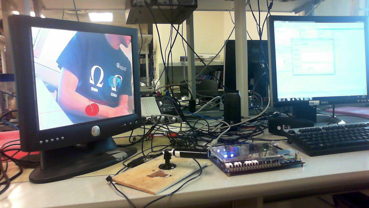
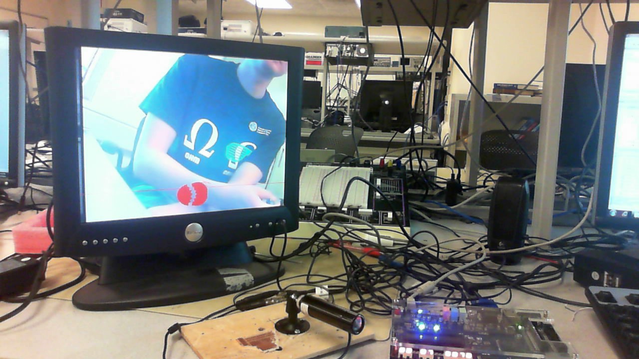
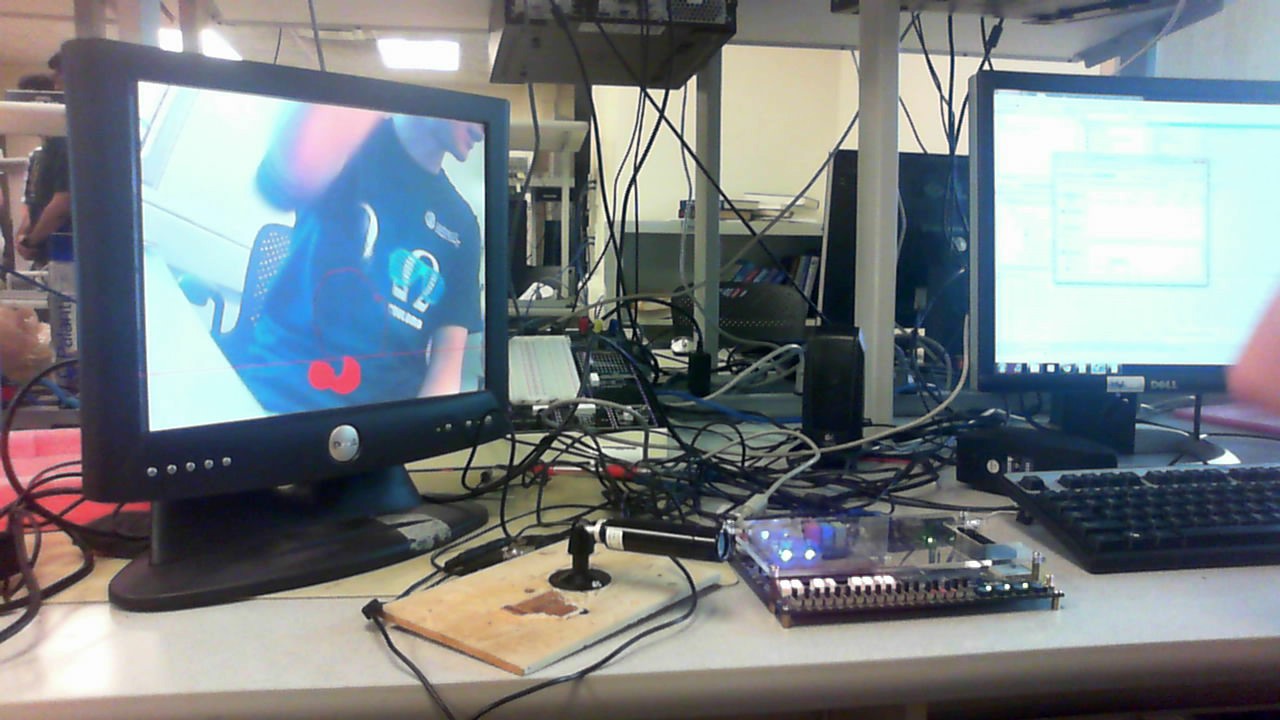
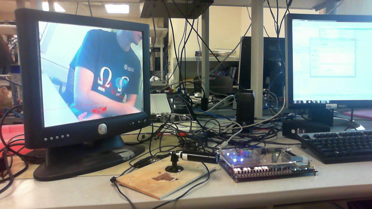
Despite the fact that “win” and count down display on the screen cannot be implemented due to not enough FPGA resources, the results of the game meet our expectation very well. The green color track goes well, the player is only able to draw the circle within the 5-second time, and the egg can be broken in different degree according to the quality of the circle. All of those game operations are what we planned to do at the beginning. The resultant game can be shown in Figures 5 to Figure 9.
|
| 5.2 | Speed of Execution |
|
The speed of our hardware program calculating the damage is very fast. We recorded the time from the game starting to check the quality of the circle to working out the damage value. The recorded time is always 90.74 ms, which means that every time the player plays draws a circle, it will take our game about 90.74 ms to calculate out its damage. It is very fast, and people feel very fluent and natural playing this game. The reason that the time is always the same is due to the fact that the boundary check and radius finding always need to check the whole 640x480 screen for two times. Considering the fix time of other states, the total calculating time is always fixed. This time is much faster than using C coding, since C coding can be synthesized into much more complex HDLs than direct hardware programming. Such complex HDL generated by C codes obviously cost much more delay. |
| 5.3 | Problems |
|
Although it is a successful game design, there has something that can be improved to make the game more reliable and interesting. For noise filtering, currently we just detect the wanted green part by checking its area. However in some cases, such as when using a poor video camera or the light of the environment is poor, there can be large area of green-color noises that interfere our detection. So two methods can be implemented to further enhance the reliability. One method is to check the step size of the moving green point. Considering the fact that the player can only draw consecutive things, the step size should not be very large. So we can add the filtering logic that if the step size is unexpectedly large, it is a noise to be filtered. Another filtering method can be time filter, with which can check the color value of the same point in consecutive time cycles to filter any unexpected change. The result also turns out that the player cannot wear green clothes to play the game. This restricts the players’ wearing, which is not very user friendly. In order to solve this issue, color detection should be changed into other detection methods such as motion detection. But at the same time the detection logic would become more complex, leading to larger game processing latency. So this is a trade-off we need to carefully handle. |
| 6 | Conclusions |
|
In the final project we designed the “egg crasher” video game which asks players to draw a good circle to smash the egg on the screen. We used a video camera, an Altera DE II board and a VGA screen to implement the game, and we choose to code it by Verilog HDL to make the game running fast. Altera’s m4k blocks were used to store necessary data, and the video camera Verilog module provided by Professor Bruce Land was used to setup the video camera. We coded the game by several logic parts, full tested each of them, and then put them together to form an interesting video game. The result turned out to be as good as we had expected. All functionalities went well, and the speed of game calculating the damage value is as fast as 90 ms. To make the game more reliable and player friendly, more color noise filter techniques can be used, and maybe the whole program can be optimized in terms of resource usage to allow timer display and fancy figures added. |
| 7 | Appendix |
| 7.1 | Commented Program Listing |
|
Top-Level Verilog Code |
| Complete Quartus II Project |
| 8 | References |
|
http://people.ece.cornell.edu/land/courses/ece5760/ |