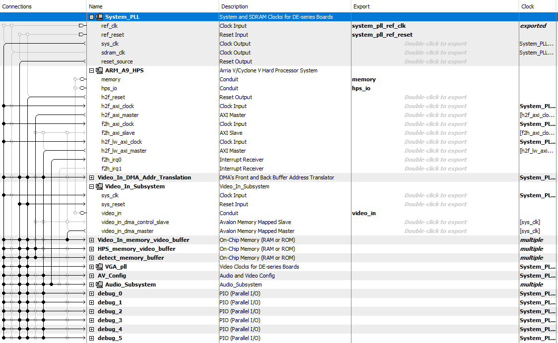
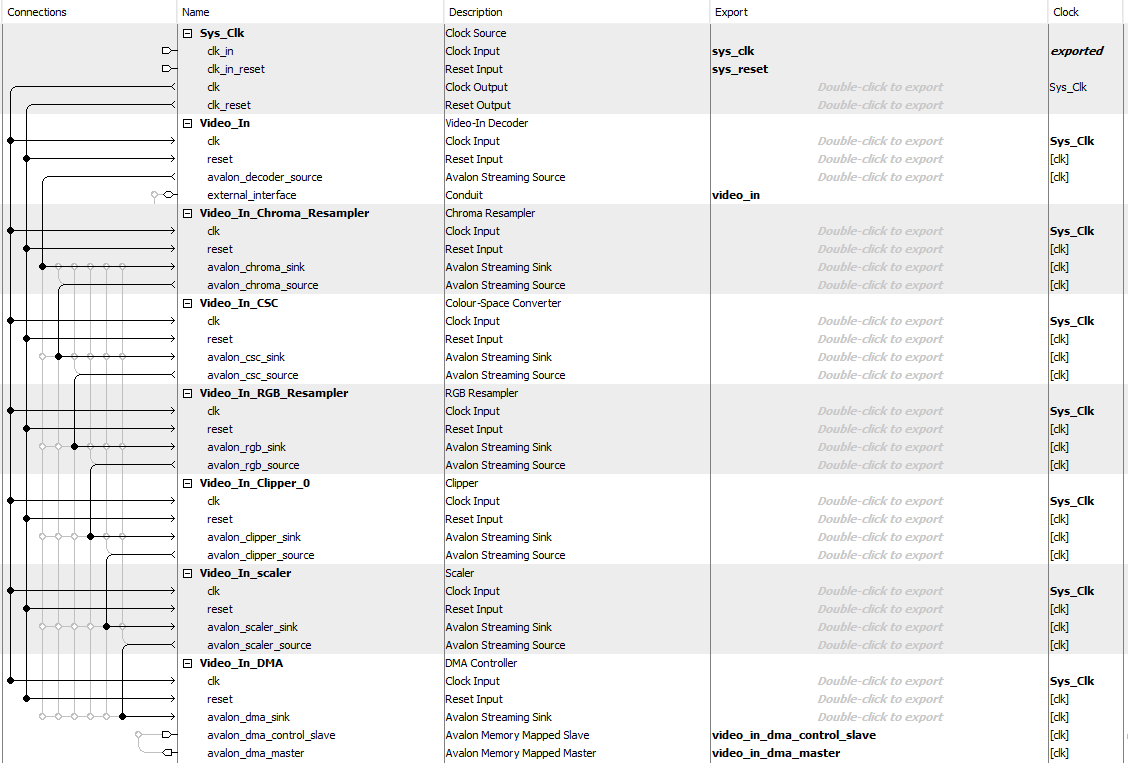
The Qsys component of the project is integral to the system’s functionality. Qsys essentially the system PLL with the logic to provide timing via the 25.175 Mhz clock, interconnects the ARM processor (HPS) to the FPGA via the heavyweight and lightweight axi busses, and integrates the camera feed (video_in), audio subsystem, and memory buffers.
The top level Qsys module - De1SoC - interconnects the system PLL, ARM, DMA
address translator, video_in subsystem (camera feed), memory buffers, audio subsystem,
and debug PIO ports. When the program is activated from the HPS, the HPS sends a signal to the
video in subsystem to turn on video capture via the lightweight bus. There are three on-chip
memory modules instantiated: video in memory buffer, detect memory buffer, and HPS memory
buffer. The video in memory buffer stores the camera feed, the HPS memory buffer stores the
graphics data, and the detect memory buffer holds the data that resembles which pixels have
been flagged when blue (or red/green) is sensed.
The video in subsystem takes in the camera feed from the NTSC camera in YCrCb 4:4:4 format. Inside the video in subsystem, the YCrCb 4:4:4 feed gets goes through the Chroma Resampler and gets converted to 4:2:2 which drops half of the Cr and Cb values, alternating every pixel which value is dropped. Then, the data enters the video in CSC module (color space converter), where the YCrCb 4:2:2 feed gets converted to 16 bit RGB. The RGB resampler then converts the 16 bit RGB data into 8 bit RGB data. The clipper and the scaler modules modify the resolution of the video stream from 720 x 244 to 320 x 240. That is accomplished by clipping the blank edges of the video feed to 640 x 240. The stream’s width is then scaled by a factor of 0.5 using the scaler module. Then, the stream is sent to the DMA where it gets transmitted to the video in memory buffer (on-chip memory).
Enabling the VGA scheme to function correctly was one of the most challenging aspects of this project. We started off using Bruce’s example “Video input from NTSC to on-chip-memory, then to SDRAM VGA using HPS, in 8-bit color”. To enable overlapping between the video feed and the HPS graphics, we tried to use the alpha blender module Qsys that revolves around combining two video streams into one. The video in would be considered background while the HPS graphics feed would be considered foreground. The alpha blender module multiplies the foreground by a factor of 'a', making it transparent over the background. However, this method did not work correctly and would not result in overlay. Advised by Hunter, the team decided to manually overlay the HPS and video feed in Quartus, which functioned fine with our custom made VGA driver from Lab 3. This was done by adveraging the video-in with HPS video data whenever SW[1] is high. One of the other issues we faced in Qsys was the wrong ordering of the video in modules. For instance, we had the scaler module accidently placed above the Color Space Converter which outputted an unusual feed on the VGA screen.
The color detection system was the part of the project that requiered the most application specific tuning. We started off by processing the video-in feed going to the overlay logic. Since the VGA feed is at a resolution of 640 x 480 that means that every pixel from the video buffer is sent to the screen 4 times. To mitigate this isue pixels are only blue if it's in the botom right corner of the 2x2 grid (x/y cordinates end in a 1). To determine if the pixel contains enough blue the B value from the RGB is compared to the G+R value. In order to tune the parameters without recompiling QSYS the G+R value is multiplied by the value from a PIO port and then added to the one in another. If the pixel is defined as blue it's added to the count of pixels in the region. The total number of blue pixels in the 8x8 square is put into the detect memory which has a second port on the HPS' heavyweight AXI bus.