| INTRODUCTION |
| BACKGROUND |
| SETUP |
| HARDWARE |
| SOFTWARE |
| RESULTS |
| TROUBLE- SHOOTING |
| CONCLUSION |
| APPENDIX |
| MORE PICS |
Hardware
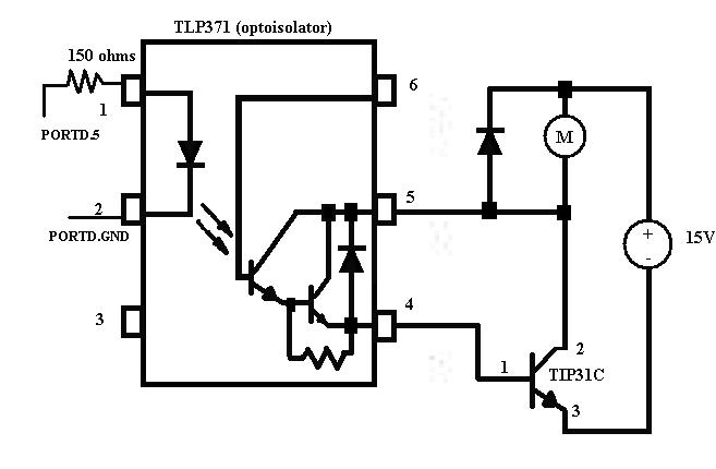
There is actually a lot of hardware associated with this design. First off I needed to build a circuit that will take a pulse from the microcontroller, (Atmel's MEGA32), and use that to regulate a stronger power source to turn the car’s motor on. To do this, I designed a circuit (with some help from Professor Land) that used opto-isolation to translate a microcontroller signal into a stronger signal. The whole idea behind opto-isolation is to create to seperate, independent circuits. One circuit will be the microcontroller and the other will be the power source connected to the race track. These two circuits need to be independent to reduce capacitance across the entire circuit as well as have to different reference voltages. I was able use the TLP317 to create the desired opto-isolation. This is shown in the schematic below. To make sure this wouldn’t fall apart with loose wires as I used this through out the semester, I soldered the whole design together onto one piece of vector board.
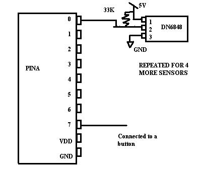
Second, I needed to attach sensors to the track. In this lab, I chose to use the DN6848,a Hall Effect sensor that is sensitive to a directional magnetic field. It only detects a strong magnetic field and outputs a logical value making it ideal for this lab. The logical value output can be used and interpreted by the microcontroller which will then adjust its PWM according. The sensors, unfortunately, cannot just be used by connecting all three pins. Instead, they are open-collector so I had to put a 33K resistor in between the output and Vdd. The output is then tied to one pin of portA of the MEGA32. To make the design more compact, I actually soldered the sensor to a small piece of vector board with the resistor connected and a wire attached to each of the pins. This would reduce the errors of temporary connections falling off the pins of the sensor.
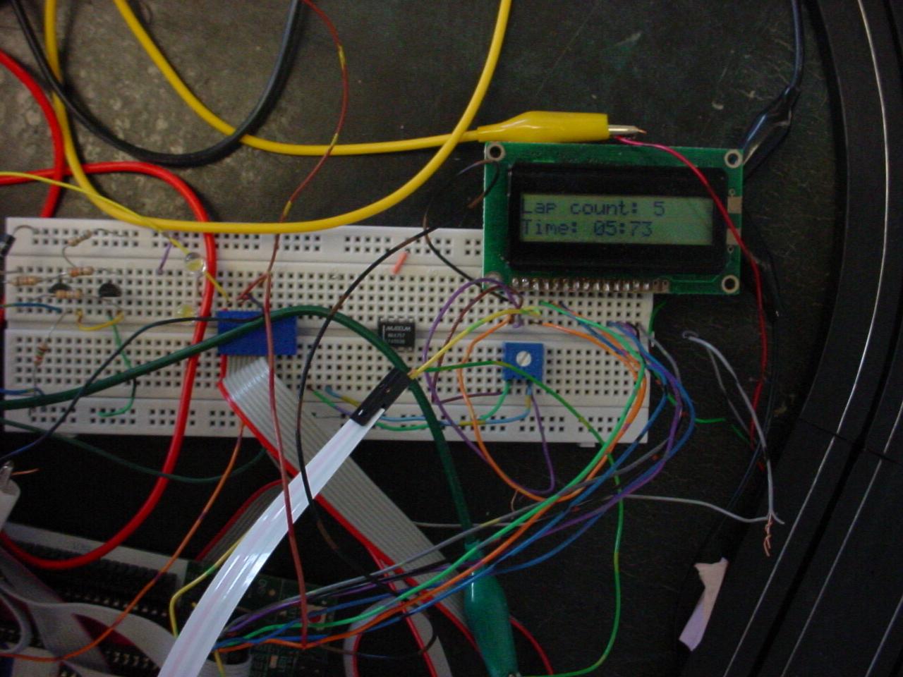
I added two other features to the lab, which would make the lab more user friendly. One feature was simply including the used a button push to turn on the car. The button push is just a connection between one switch and a an input pin for the MEGA32 For the other feature, I hooked up one of the ports to the LCD display. The LCD is a little more involved. To my advantage, Professor Land already had a LCD wired to a connector so that all I would have to do is plug it into one of the ports of the STK500. The actually pinout of the LCD is given below.
	      [LCD]   [MEGA32 DIP40]
	       1 GND-  GND
	       2 +5V-  VCC
	       3 VLC 10k trimpot wiper*
	       4 RS -  PINC.0
	       5 RD -  PINC.1
	       6 EN -  PINC.2
	      11 D4 -  PINC.4
	      12 D5 -  PINC.5
	      13 D6 -  PINC.6
	      14 D7 -  PINC.7

	    *(trimpot ends go to +5 and gnd)