
Darshan, Sai, Ankur and Bruce.
Introduction top
" A security system which unlocks based on hand gestures."
-Project Sound Bite

Fig.1 Gesture Based Security Lock
Our final project is to design a security system which can be unlocked by means of a stored gesture pattern. The idea is to create a box like assembly, in which the user places his hand, makes a defined gesture and unlocks the system. Basically, there is a mechanism that allows the user to save a gesture pattern. Once that is done, the system goes in lock state. When the user enters his hand in the box, he tries to recreate the same pattern. If he is able to do so, the system unlocks. If unable to, the system remains locked.
High Level Design top
Rationale and Source of Our Project Idea
The idea is inspired by the popular mobile phone unlock feature where basically you draw a pattern on the screen and the phone unlocks. We wanted to create a similar system which could be used in any security application, as simple as opening the door of the house based on the gesture. The attractive feature of the project is that the user makes the pattern in the air and not on any surface. Also, we have given the user the flexibility of changing the pattern whenever he wishes to do so.
The whole idea is to provide a fully functional product to the user who can interface the system to any electronically controllable device. The user can himself create patterns, store them and open the device only by himself, giving him the freedom to lock and unlock the device without any kind of key required.
Background Math
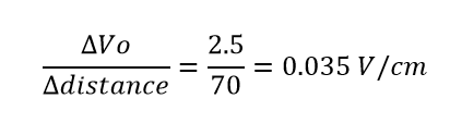
The infrared sensors we are using is 'Infrared Proximity Sensor - Sharp GP2Y0A21YK' by the vendor 'Sparkfun Electronics'. This sensor gives an analog voltage in the range of 0-3 Volts for distance between 10-80 cms. Thus, change in voltage per cm change in output can be given as :
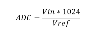
This implies at minimum distance ie 10 cms, the sensor gives output of 0 volts and at maximum distance ie 80 cms, the senor output is as high as 3 volts. As the maximum voltage was around 3V, we were motivated to use the ADC reference as the internally selected 2.56 V, to see better sensitivity. The output of the ADC is given as :
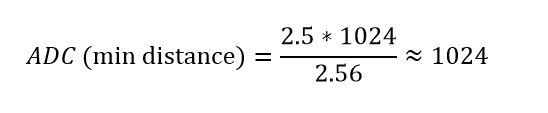
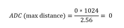
For minimum distance of 10cms and maximum distance of 80cms and Vref =2.5 V for which ADC output would be :
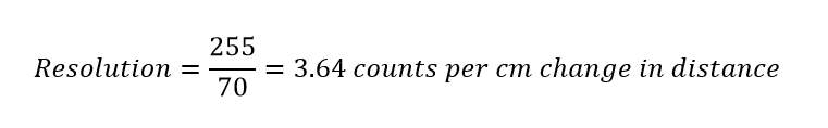
We just used the higher 8 bits of the ADC output ie ADCH register. The ADC values at ADCH will thus vary from 0 to 255. The resolution ie change of one bit per change in cms can be given as :
Logical Structure
We needed some kind of sensors which could accurately measure the gestures of the user. After looking at various sensor options used to measure distance, we zeroed in on IR proximity sensors which work on the basic principle of transmitting IR light from the IR LED transmitter and receiving back on the IR photodiode which based on the intensity of the received light determines the proximity to an object. So we used four IR proximity sensors to give a decent usable region for the user to draw his pattern on.

Fig.2 Basic Operation of IR Sensor
The IR proximity sensors gave us an analog voltage proportional to the distance of the sensor from a flat object placed in the user's hand for drawing the patterns. The analog voltage from each of the sensor is given to the ATMega1284P, which utilizes the internal Analog to Digital Converter, to convert this analog voltage to digital signal which can be utilized by the microcontroller for further processing. We provide a switch to toggle from the store and check mode. In the store mode, the user can store the pattern using which he wants to lock the device. In the check mode, he tries to recreate the pattern and unlock the device. If an incorrect pattern is created, the device remains in the locked state. We show an LED for demonstration purpose, which can be substituted by an electronically controlled device.

Fig.3 Logical structure of the system
Hardware and Software Tradeoffs
As this is a security system, we need to at all times make sure it unlocks only when correct pattern is exactly reconstructed. It is humanly impossible to always draw the pattern at the same speed. The number of readings taken by the sensors is directly dependent on the speed of the user while creating the pattern. The system has to compare this pattern with an internal stored pattern, thereby at every attempt we get different number of readings. To validate an attempt as successful we need to incorporate an algorithm which takes care of this complexity and define minimum number of reading required to validate an attempt. Also, to make the system speed invariant, we need to implement an algorithm which takes care of comparison with different number of readings. Thus a more complicated software had to be designed to deal with hardware oriented speed issue.
Standards
There are few ISO standards which deal with human gestures and software relationships like ISO 9241-410:2008, which specifies the assessment methods for laboratory use of human gestures for hardware software interfaces. "ISO 9241-410:2008 specifies criteria based on ergonomics factors for the design of physical input devices for interactive systems including keyboards, mice, pucks, joysticks, trackballs, trackpads, tablets and overlays, touch sensitive screens, styli and light pens, and voice and gesture controlled devices. It gives guidance on the design of these devices, taking into consideration the capabilities and limitations of users, and specifies generic design criteria for physical input devices, as well as specific criteria for each type of device."
Relevant Patents and Copyrights
There is currently a patent remotely related to our project, EP 2166487 A3 - Security system utilizing gesture recognition. The patent is in general relevant to any gesture based system, though it does not have intricate details which match with our project definition.
Hardware top
Overview

Fig.4 Circuit for switches and LED's

Fig.5 Placement of sensors
The most important hardware that we used are the four infrared proximity sensors GP2Y0A21YK. Each sensors requires an external supply of 5 Volts. These sensors detects the hand movements in the space and hence the pattern generated by the user. The sensors are able to detect any obstacle within a range of 10 to 80 cm. We use this property of the sensors and try to store the pattern generated by the hand that acts as an obstacle. The output of the sensors is an analog output voltage. The output voltage obtained is 0 volts for the obstacle very near to the sensor and 2.56 Volts for the maximum distance. The analog output is fed to the internal ADC of the microcontroller that will map the corresponding analog readings to the equivalent digital output. The hardware circuitry also consists of two switches, push button and toggle switch. One switch is used to accept the pattern from the user when pressed. The toggle switch is used to run the circuit in 'store mode' or the 'check mode'. In the 'store mode', the circuit accepts the pattern from the user and stores it for further comparison. In the 'check mode', the user again tries to recreate the stored pattern and check if it matches with the earlier pattern. If the pattern matches, it will indicate that the password is correct and the lock will open. To indicate the match, we connect the LED to the controller that glows if the pattern matches. The sensors are connected to pins A2, A3, A4 and A5 pins of the microcontroller. The push button is connected pin B0 and the toggle switch is connected pins B1 and B2.The indicator LED's are connected to pins C0 and C1 of the microcontroller.
Trials and Tests
The first test was to connect the distance sensors to the internal ADC of the controller and observe the corresponding change in the digital output. Also, the major issue was to run the four ADC simultaneously. However, this is not possible as the controller does not allow the internal ADC to rum simultaneously. We need to take a continuous reading from the sensors in the real time, so we run the four ADC after a regular interval of time. Hence, we achieved to take the input from all the sensors at a small interval of time.

Fig.6 Testing of the system
The other issue that we faced was to decide the optimum position of the sensors on the outer box assembly. We first tried to attach the sensors on the four corners of the box. But later we realized that with the following design, there is a lot of space for the black spots, where the sensor is unable to detect any movement. Hence, we concluded that this design is not efficient as well as reliable. So, we had to come up with a design that is not only reliable but also has less black spot and cover maximum area. Then we decide to attach all the four sensors in the horizontal plane at the top of the box as shown in the diagram. This will cover maximum area and also it will detect the patterns generated easily in the horizontal plane where the user is intended to make the pattern. After deciding the position we connected the switches and then tested if the desired design was compatible with the algorithm written by us. We also tested the working of the switch and the working of the LED.
Software top
Overview
The software part for this project is very important because matching and verification of the pattern is done in the software. The level of security of the system lies in the software .There are mainly three types of actions to be performed by the software: ADC conversion from the proximity sensors, mode selection and gesture activation using switches, input reading and pattern matching.

Fig.7 Flowchart for the lock/unlock process
ADC Conversion
The first task that we focused on while starting the project was to take measurements with the proximity sensors. This involved activating four channels of the inbuilt ADC's of the microcontroller and creating a loop where the four channels are constantly multiplexed and proximity readings are continuously taken from them.Here we are using a divide by 128 prescalar and we use internal reference voltage as 2.56V.
Algorithm for four channel ADC multiplexing
Step 1 : Enable first channel of ADC.
Step 2 : Start ADC conversion after setting appropriate prescalar.
Step 3 : Wait until ADC is complete.
Step 4 : Write the higher nibble of ADC to a desired variable.
Step 5 : Turn off current channel and enable the next channel by varying ADMUX.
Step 6 : Repeat for up to four channels.
Repeat the process continuously.
Based on this algorithm, we were able to successfully get the values of distance from the proximity sensor on a scale of 0 to 255 after appropriate conversion of output voltage in the ADC with a reference voltage.
Selection Switches
The next operation we focused on was to implement a toggle switch in the design to toggle the mode of the lock from store mode to check mode. We also added a push button to start storing or checking the pattern. The lock was programmed in such a way that the input is taken in the appropriate mode based on the state of the switches.
Algorithm for switches and input
Step 1 : Check the state of the toggle switch.
Step 2 : Based on the state, enter the check or store mode.
Step 3 : As long as the push button is pressed, perform ADC conversion and write the readings to the appropriate arrays.
Repeat the process continuously.
Storing and Matching Patterns
This is the most complex part of the project. In this art, the user should be able to create and store a desired pattern and should be able to successfully authenticate his identity by recreating the stored pattern.
Store Mode
In the store mode, when the push button is pressed, the four channels of ADC's continuously do conversions and write the values to variables b1,b2,b3 and b4 respectively. Due to the overall size of memory available and to avoid a large amount of data to be written to the arrays, we write the values on every tenth conversion from each channel to the array. After the push button is depressed, the final four arrays are obtained and stored for checking later in the check mode. If the push button is pressed again, the contents of the arrays are reset and the entire process is repeated again and new values are stored.
Algorithm for store mode
Step 1 : If toggle switch is in store mode, enter store mode.
Step 2 : While the push button is pressed, start ADC conversions in the four channels.
Step 3 : For every tenth cycle, write the value of ADC into the store arrays b.
Step 4 : When the push button is released, stop ADC conversion.
Repeat the process continuously.
Check Mode
In the check mode, the user should be able to recreate the pattern and an algorithm for verifying the pattern with the saved pattern was developed. When the push button is pressed, the ADC's do conversion and every tenth value of each channel is saved into arrays a1,a2,a3 and a4. After the button is released, the final array is obtained and now the comparison is done. In the comparison algorithm, we use a linear search across the four arrays. The first elements of all four arrays of "a" are searched in the corresponding arrays of "b" and if the difference of the values is within a threshold for all four arrays, a line match counter is incremented and the next elements of arrays "a" is searched from this point in arrays "b". If a match is not found till the end of arrays "b", the reference line is set back to the last found index of arrays "b" and the next elements of arrays "a" are searched. In this way, the process is repeated until all elements of arrays a1,a2,a3 and a4 are searched. According to the desired level of security, we have set that if at least one fourth of elements in the stored pattern are matched in the checked pattern, then a match has been found.
Algorithm for pattern matching
Step 1 : Check if the toggle switch is in the check mode.
Step 2 : While the push button is pressed, take ADC measurements and write to arrays a1,a2,a3 and a4 for every tenth reading.
Step 3 : After the button has been released, obtain the final arrays and prepare for pattern matching.
Step 4 : Initialize a line counter for number of matching lines found.
Step 5 : Check if the elements of arrays "a" are found in arrays "b". Here a threshold of 15 is kept for accuracy. If all four elements are found, keep the next element in "b" as reference point and increment the line counter and search for the next elements of "a" in "b" from the reference point. If the elements are not found till the end of "b", search for next element in "a" from the reference point in "b". Repeat this process until all elements in "a" are searched.
Step 5 : If one fourth of the elements in b are matched with the elements in a, then we define that a match has been found. For higher accuracy, we can change this ratio to one third or one half according to the level of security.
Step 6 : Turn on the corresponding LED according to a correct attempt or incorrect attempt.
Results top
Speed of Execution
Speed of execution of the program mainly depends on the performance of the controller and its internal processing time of the ADC. The time taken by the ADC of the controller to convert the analog input from the sensors to the corresponding digital output is the conversion time of the system and it plays an important role while taking in to account the overall timing considerations of the system. Also, it should be taken care that when the pattern is stored in the controller, the pattern should be stored slowly in order to ensure maximum look up points (comparison) in the array. This means that the stored array should always be greater than the checking array. This will avoid ambiguity in the system and make the system more reliable as it has more points to compare.
For increasing the safety of the system, we need to have a lower limit of the speed with which the pattern can be checked. This limit is set at one fourth of the speed of storing the pattern. The upper limit on the speed is the speed of the stored pattern. Thus the check speed can be anywhere between one fourth the store speed and the store speed. For instance if the user takes 10 seconds while saving a pattern, he should re-create the same for a valid unlock trial in anywhere between 2.5 seconds to 10 seconds.
Accuracy
As mentioned in the earlier section, the proximity sensor is accurate within the range of 10 to 80 centimeters. This needs to be taken into consideration while making a pattern as our whole project is based on the distance and obstacle detection. Also in order to obtain the output correctly, we have made some trade-offs in the algorithm. The first one is that while comparing the pattern generated by the user with the stored pattern, we have kept a threshold of that only one-fourth of the array should match. If one-fourth of the array in the check mode matches with that stored, than we assume that pattern generated was approximately same. Also, we have given a threshold of +/- 15 of the reading obtained from the ADC. These both adjustments are needed as it is very difficult to generate the stored pattern at the same location and with the same accuracy. Hence, we have provided the user with the following trade off in order to obtain accurate results.
To test the accuracy we took a sample pattern as shown in figure 8.

Fig 8. The stored pattern
The pattern was stored by Ankur and the set of readings for the same can be seen in figure 9. As 13 lines are stored, minimum 4 of them should match as per the speed requirement of more than one fourth. Each of us tried to make 10 unlock attempts for the same pattern and the results can be seen in the table.

Fig 9. Stored pattern on Putty
Figure 10 shows the pattern checked for match by Ankur, where the unlock attempt is successful.

Fig 10. Match found
Figure 11 shows the pattern checked for match by Sai, where the unlock attempt is unsuccessful.

Fig.11 Match Not found
The table below shows the trials and successful attempts by the three of us.
| Name | Number of Successful Attempts | Percentage of Accuracy |
|---|---|---|
| Ankur | 9 | 90 |
| Darshan | 7 | 70 |
| Sai | 8 | 80 |
As seen according to the current system, the accuracy if the same person trying to recreate is around 90-100%. For any other person trying it falls in the range of 70-90%. We can increase the system accuracy by increasing the thresholds, but this will affect the safety of the overall system.
The system has satisfactory performance and high accuracy. We even tested for incorrect similar patterns which the system clearly passes off as unsuccessful attempts. There is a clear tradeoff between the accuracy to safety, out of which we believe safety is of utmost importance as it is a security system.
Safety and Interference
This project is very safe. Since the voltage and the current ratings are very low, no harm would be done to the user even if the wire was frayed or the circuit was shorted. All the wires are insulated. There are no dangers relevant to this project. While placing the proximity sensors, we found that if the sensors are placed very close to each other, they interfere with each other. This means that there is a possibility that the signals transmitted from one sensor may be received by the receiver of the other sensor. This is not desired as it will create ambiguity in the system and the results obtained will not show accurate results. Hence, we place the sensors in such a way that the transmitter of one sensor is besides the transmitter of another as shown in the diagram.
Usability
The system was designed to implement a security system that takes a pattern generated by the hand as the pass key and if it matches when recreated the lock opens. The user needs to keep in mind that the system not only matches the pattern but also the position of the pattern. In order to make it more user friendly, we provide grid pattern in the background that will help the user to remember the exact position of the pattern.
Conclusions top
Results vs. Expectations
We wanted the system to work with actual test patterns, so we comprehensively checked different patterns and verified the accuracy of the system. As far as the testing was concerned, we obtained accurate results for all the tested patterns. Initially, we believed that faster patterns could be tested, but later on we specified minimum number of readings required to unlock, to increase the reliability of the system. Also, we expected to be able to store small patterns and test accordingly, but we had reliability issues while using smaller patterns because of insufficient comparison involved. Overall, our system performs satisfactorily, and can be effectively used to create a gesture-based secure unlock. Given more time and budget, we could have made the system 3D by which change in the third dimension could be used to model the system, which would increase system accuracy and give the user another dimension for creating the patterns.
Intellectual Property Considerations
The entire hardware design of this project was done without referencing any other designs or the intellectual property of others. The software we wrote is also mostly of our own design, although we did utilize ideas learned from Bruce Land's example code from the previous labs, we did not explicitly copy any of those programs. We did use the UART.c and UART.h files, which are under the "Beer-Ware License" and were written by JoergWunsch.The patents listed previously are only related to our project and we did not directly use any of the ideas claimed within them. We did not reverse-engineer a design, so there should be no patent or trademark issues.
Ethical Considerations
Throughout this project, we strictly adhered to the IEEE Code of Ethics. In particular, we believe that two points of the code are pertinent to the way we conducted ourselves this semester. First, the code states that a member of the IEEE must "seek, accept, and offer honest criticism of technical work, to acknowledge and correct errors, and to credit properly the contributions of others" This was very relevant to us at the beginning of the final project when we were first hashing out details with our TA and with Dr. Land. We made sure to discuss our project ideas with our TAs and Dr. Land early in the project planning phase. Secondly, "to be honest and realistic in stating claims or estimates based on available data". We were honest in writing this report and explaining our project and how we designed it. As ethical members of the electrical engineering community, in our demonstration we made sure to discuss all of the aspects of our project that do not currently work, as well as flaws in the current design. Throughout the semester, we adhered to the entire IEEE Code of Ethics, but we thought our specific adherence to the above two points were noteworthy.
Legal Considerations
As far as we know, there are no legal considerations involved with this project
References top
Datasheets
MEGA1284 Datasheet
IR Proximity Sensor Datasheet
Vendors
Sparkfun Electronics
References
Hand Motion Chess
Acknowledgements top
We would like to acknowledge our advisor Prof.Bruce Land for the constant motivation and inspiration to think beyond the ordinary.We would also like to acknowledge the FALL 2013 TA's Cameron Glass,Roland Kreiger,Tian Gao and Aadeetya Shreedhar for their support. We obtained some code for serial communication, ADC conversion in C and template for webpage in html from the 4760 webpage
Appendices top
A. Division of Work
| Task | Member |
|---|---|
| ADC and Sensor interfacing | Ankur Thakkar and Darshan Shah |
| Check and Store mode algorithm | Ankur Thakkar and Darshan Shah |
| Pattern Matching Algorithm | Saisrinivasan Mohankumar |
| General Circuit assembly | Shared |
| Report Preparation | Shared |
| Webpage Design | Saisrinivasan Mohankumar |
B. Parts List and Costs
| Part | Vendor | Cost/Unit | Quantity | Total Cost |
|---|---|---|---|---|
| Atmega 1284p | Lab Stock | $5 | 1 | $5 |
| Custom PCB | Lab Stock | $4 | 1 | $4 |
| IR proximity sensor (Part #SEN-00242) | Sparkfun Electronics | $13.95 | 4 | $55.8 |
| 3 Pin Jumper cable (Part #SEN-08733) | Sparkfun Electronics | $1.5 | 4 | $6 |
| Bread Board | Lab Stock | $6 | 1 | $6 | Power Supply | Lab Stock | $5 | 1 | $5 | Toggle Switch | Lab Stock | $0 | 1 | $0 |
| Push Button | Lab Stock | $0 | 1 | $0 |
| LED | Lab Stock | $0 | 2 | $0 |
| 330ohm Resistors | Lab Stock | $0 | 5 | $0 |
| Wires | Lab Stock | $0 | NA | $0 |
| Cardboard Frame | Lab Stock | $0 | 0 | $0 |
| Black Duster(obstacle) | Lab Stock | $0 | 0 | $0 |
| TOTAL: | $81.8 |