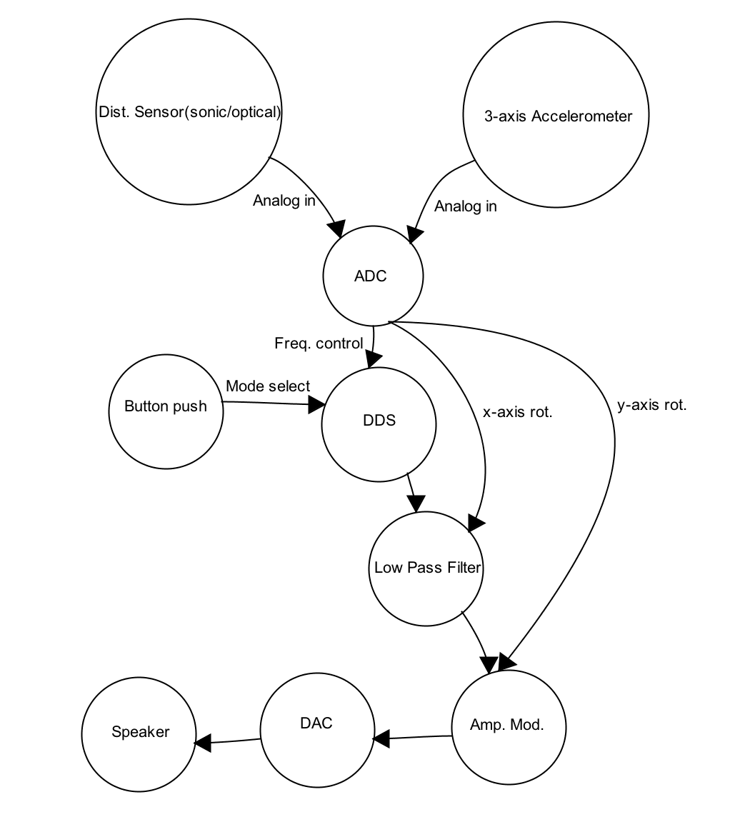
MotionWave

"A motion controlled synthesizer"


"MotionWave is a PIC32-based monophonic synthesizer that is entirely controlled by the motion of the hands.”


System Overview

The main motivation is to create a portable, affordable musical tool for people to carry with them all the time. Having the instrument motion controlled, users do not need to know much about music theory or notes; users will use the sound as feedback. The UI is supposed to be easy to learn and easy to use, therefore anyone can make music at anytime. By breaking away from traditional instruments, this project is for both musicians and non-musicians, as well as for young children for educational purposes. Altering the distance between hands will change pitch, and changing the orientation of both hands will alter the amplitude (volume) output and vary the cuttoff frequency of a digital lowpass filter. Different modes of operations can be simply changed by the press of a button, which will change the scale and range, making it easier and harder to play.

More Specifically:

Coordinate definition: X-axis is perpendicular to the front of a body and parallel with eyesight line. +x is away from the body. Y-axis is the horizontal in the left and right direction. +y is towards the right. Z-axis is up and down and +z is down towards the earth.

Controls:

Moving in the x-axis (also varying distance between hands) will change pitch; moving further away produces higher frequency notes. Rotation about y-axis will change output amplitude; rotation away from the body increases the volume. Rotation about x- axis will change the cutoff frequency of a digital lowpass filter; rotation in the clockwise direction will increases the cutoff frequency (open up the filter).

Modes of Operation:

Continuous mode: 2 octave range (C4 - C6), chromatic scale with 8 increments between each half step.

Chromatic 2oct mode: 2 octave range (C4 - C6), chromatic scale.

Chromatic 1oct mode: 1 octave range (easier to play) (C4 - C5), chromatic scale.

Major mode: 2 octave range (Bb3 - Bb5), Bb major scale.


Demo


Hardware Setup

Overall

Top View

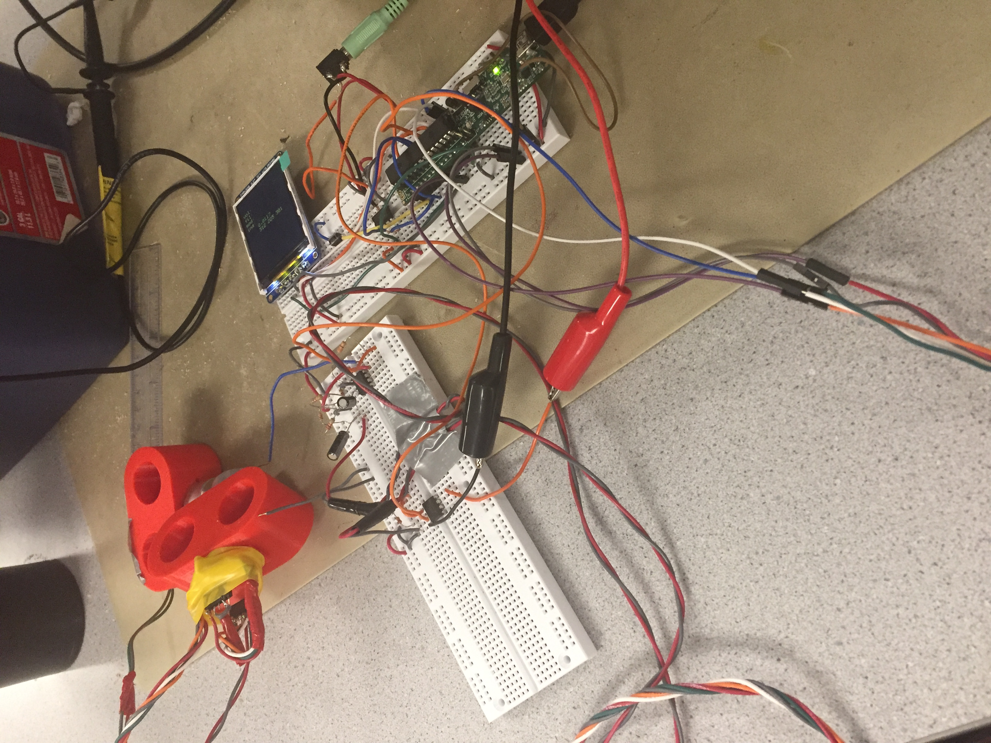
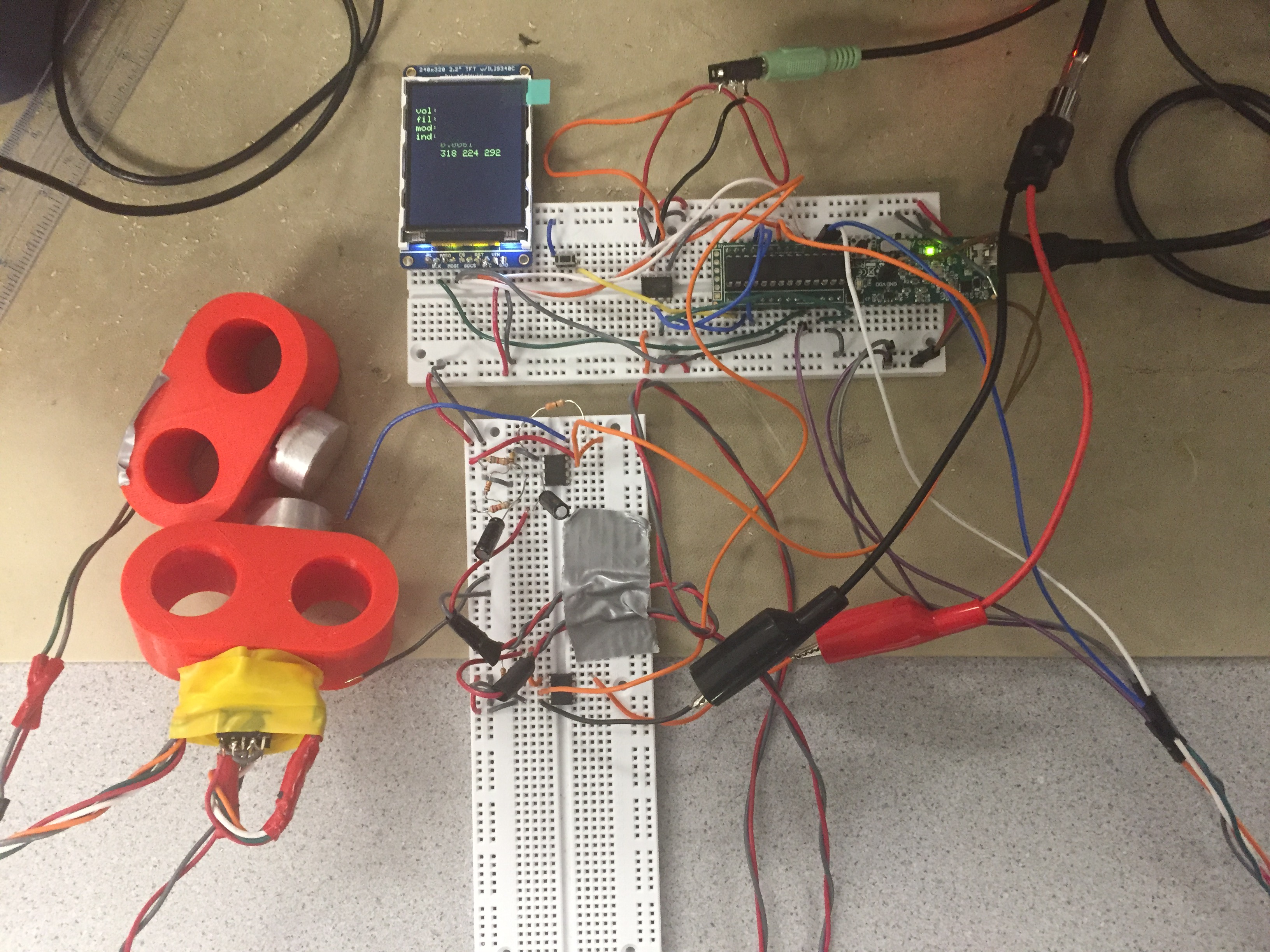
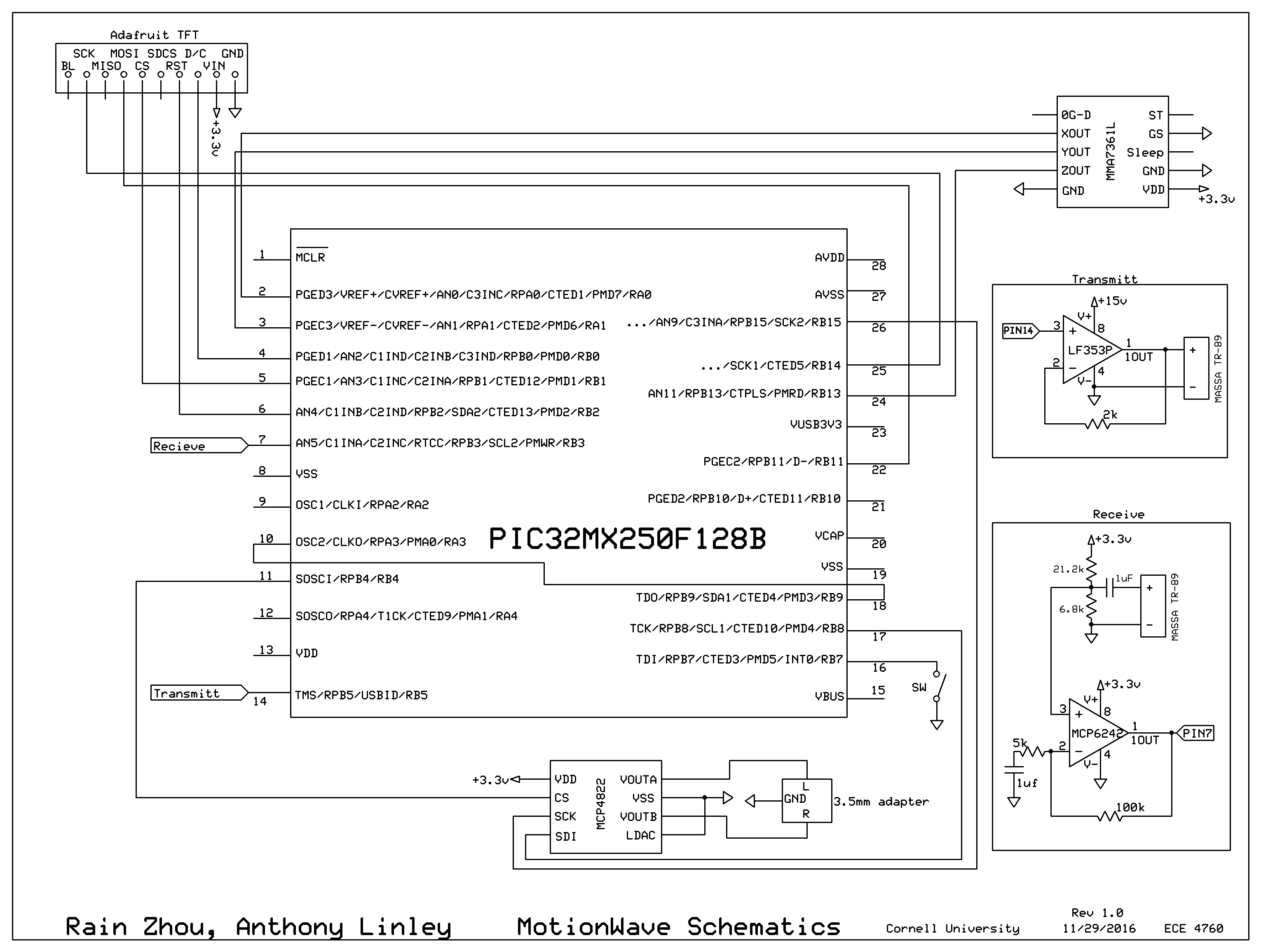
This project requires a good amount of hardware setup to achieve music playing. In order to detect the distance between user’s two hands, an ultrasonic transducer (Massa TR-89) is used on each hand; one is transmitting and the other one is receiving. A 3-axis analog accelerometer is used to get hand’s orientation because the gravity is always the same direction. We made a conscious decision to choose an analog accelerometer because the interface is more straightforward than a digital one and using ADC of the board is fairly simple. A DAC (MCP4822 from lab 2) is used to output the sound waves to a 3.5mm adapter.

In this project, we decided to use Microstick II as our development platform for the PIC32 MCU, just like we did in all of the labs, because of simplicity and familiarity. As shown in the circuit schematics in the Appendices section, the main hardware that the PIC32 is interfacing is with the TFT LCD screen, MCP4822 DAC which connects to 3.5mm adapter, the accelerometer, transmitting module and the receiving module. Connection to the TFT LCD screen and the DAC is fairly straightforward and just like the previous labs. MCP4822 DAC uses SPI clock 2 (Pin 26) and has both A and B output channels connected to the 3.5mm adapter. However, the sound output is monophonic and A and B channel output the same wave. For distance detection, we need throw an interrupt when the receiving voltage is above certain threshold. Since we are using the Vref internal comparator, we need to connect pin 10 with pin 18.

Accelerometer

MMA7361L is a low power, 3-axis analog accelerometer featuring a 1-pole lowpass filter, self-test, 0-gee detect and some other features. MMA7361L can share the same VDD as the PIC32 (+3.3V) and has two modes: +/-1.5 gee and +/- 6 gee. Since we are only sensing gravity, we select +/-1.5 gee mode to have as much resolution as we can. To do so, we have to ground the GS pin. We can leave 0G-D, ST, and Sleep pin unconnected. XOUT, YOUT, ZOUT are the analog output pins and are connected to PIC32’s AN pins, specifically pin 2, pin 3, and pin 24.

Transmitting module

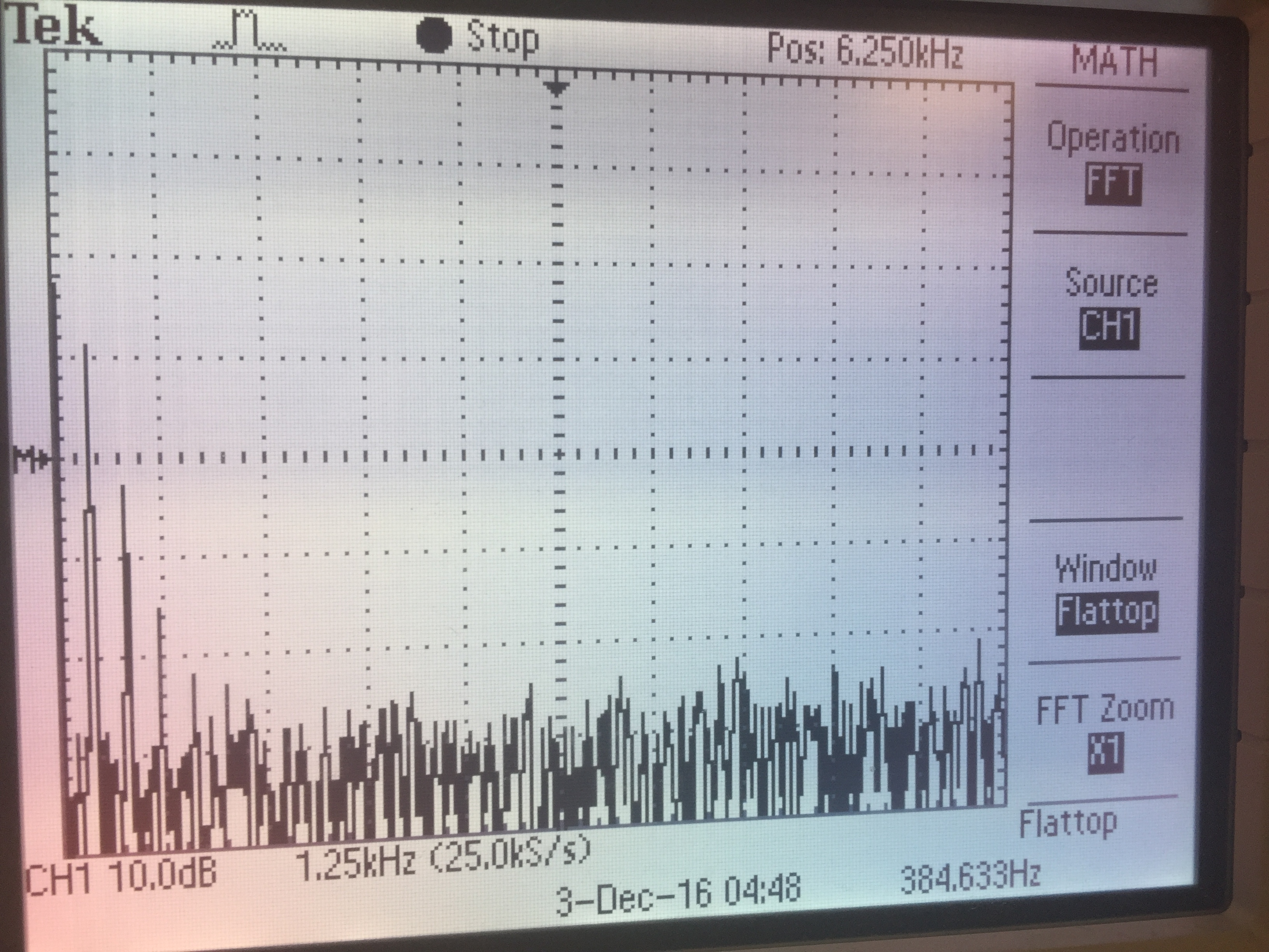
Massa TR-89 is a very cheap analog ultrasonic transducer and it just has a + and a - pin. The voltage of the PIC32 is not enough drive the transducer loud enough. Through experimenting, we found out that 15V of PWM works very well for our application (distance sensing between 0 - 1.5m). We connect the PWM output (pin 14) to the positive port of LF353. LF353 is a wide-bandwidth op amp from TI and can use voltage up to 18V. We originally wanted to create a non-inverting op-amp of gain of 5:1; however, accidentally, we got 0-15V PWM output from a unity gain buffer setup. We simply cannot explain the reasoning, but with 3.3V PWM input, we were able to get 15V PWM output at the same frequency.

Receiving module

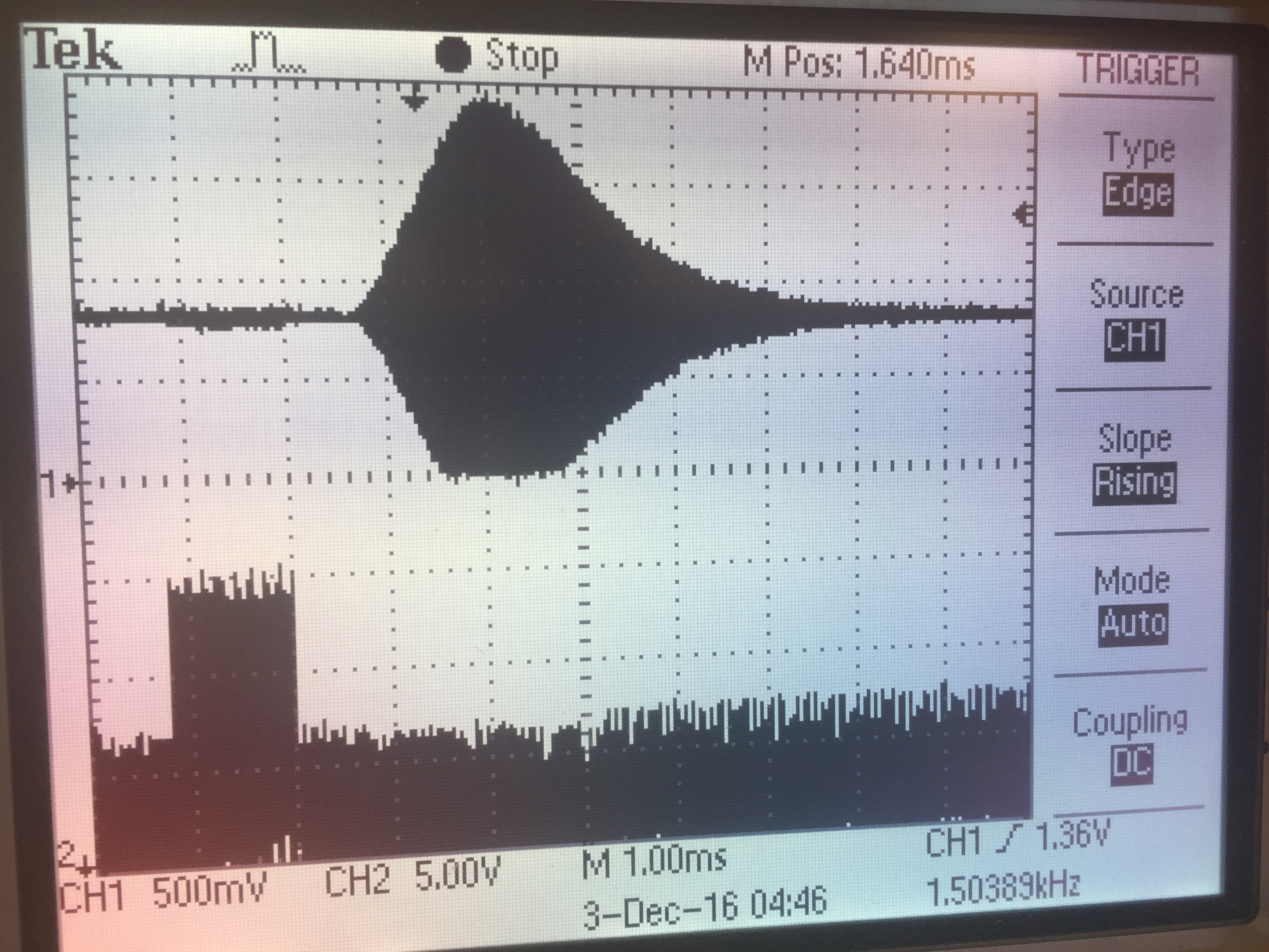
The receiving transducer produces a set of growing and then decaying oscillations. The really good way to process this signal is to invert the negative waves and low-pass the signal so that we get a smooth growing and decaying voltage instead of a bunch of sine waves. However, since we turn the comparator off after the first trigger until the next set of waves, it was not necessary for us to process the input signal. However, we do need to amplify it.

We connect the positive pin of the transducer to a voltage divider to offset the voltage so that when there’s no input, the voltage hovers around 0.8V, and the input signal can trigger the 1.2V internal comparator. If we have the neutral voltage any higher, the noise can actually trigger the comparator erroneously. The signal then is connected to the positive port of MCP6242, a low-bandwidth op amp (from lab 4). Non-inverting amplifier is implemented with the intended gain of 20:1. However, the bandwidth of MCP6242 is only good up to 550 kHz, so the realistic gain we are getting is about 10:1. The output of the op amp is then fed back to pin 7 of the PIC32.


Software Design

The main structure of the software design is as follows:

The full code with comments is attached at the end of the report in Documentation and Answers section.

Setup

Code uses “config.h” for basic setup and sets clock speed at 40 MHz (so SPI is at 20 MHz). Threading library "pt_cornell_1_2.h" is used. “Tft_master.h” and “tft_gfx.h” are used for using the LCD. “math.h” is needed for sine function. “Stdbool.h” is needed for Boolean variables. We also define two macros, two32 and Fs which is the sampling frequency which is set to 55000. Additionally, macros are set up for fixed point calculations. We also set up DAC channels A and B.

#define DAC_config_chan_A 0b0011000000000000
#define DAC_config_chan_B 0b1011000000000000

Followed by setting up SPI channel 2 to be used and a max of 20 MHz for our DAC. Then we create 4 different look up tables to be used for different scales which correspond to different playing modes. The values of these tables can be seen in the full code. Finally we set up our variables that will be needed for our DDS, phase_incr, which holds the frequency value receieved from a lookup table, saw_wave which holds the value of phase_incr and is shifted 20 bits and then stored into the final variable, DAC_data, which holds the value of the frequency that is output from the DAC.

ISR

We have 3 Interrupt Service Routines. One used to send PWM pulses, one using the input capture unit to calculate the distance between our sending and receiving sonars and one to output values to the DAC in order to produce sound. The first ISR is used to simply close the OutputCompare2 and timer1. The second ISR stores the value from the Input Capture unit into capture1 and the previous value of capture1 into last_cap. Then any capture1 is assigned to dist if it is greater than 400.

Our final ISR handles our direct digital synthesis in order to output sound using a 12 bit DAC. We first assign our variable saw_wave with the value from our value phase_incr, which is set during our sound thread. We then perform some fix16 arithmetic on the variable saw_wave after shifting it 20 bits so it can be output to the our 12 bit DAC. After this we check to see if the value of our filter variable is less than 225. If so DAC_data is sent through a digital 1 pole low pass filter. Then DAC_data is output through both SPI channels. The code for the DAC output ISR is shown below.

mT4ClearIntFlag(); saw_wave += phase_incr;
DAC_data = fix2int16(multfix16(amp, int2fix16(saw_wave>>20)));
if (filter < 225) {
out=multfix16(int2fix16(DAC_data), a0)+z1;
z1 = multfix16(int2fix16(DAC_data),a1) +z2 - multfix16(b1,out);
z2 = multfix16(int2fix16(DAC_data),a2) - multfix16(b2,out);
DAC_data=fix2int16(out);
}
//transaction for chan A
mPORTBClearBits(BIT_4);
while(TxBufFullSPI2());
WriteSPI2(DAC_config_chan_A | DAC_data);
while(SPI2STATbits.SPIBUSY);
mPORTBSetBits(BIT_4); //end transaction

//transaction for chan B, same stuff though
mPORTBClearBits(BIT_4);
while(TxBufFullSPI2());
WriteSPI2(DAC_config_chan_B | DAC_data);
while(SPI2STATbits.SPIBUSY);
mPORTBSetBits(BIT_4); //end transaction

Threads

We have four different threads that are put into a round robin scheduler in our Main function. We have an ADC thread, a PWM output thread, a sound thread and a print thread. Each thread will be mentioned in detail below.

The ADC thread handles all analog to digital conversion dealing with our 3 axis accelerometer; this thread also initializes variables needed for our digital low pass filter in our DAC output ISR. We start by reading each of the different axes and storing the values into our x, y and z variables. Next we store the current value of our volume and filter variables into last_vol and last_filter respectively. We do this to keep track of the previous value before the variables are updated below. We then use the values of x and z to get the values that will be used to change the volume that is output and the filter variable which changes the cutoff frequency. The code for that will be shown below this paragraph. We also map both our volume and filter variables to a specified range; volume ranges from 0-160 and the filter variable ranges from 0-225. Next we set some variables that are needed for our digital low pass filter to give us our desired output. All low pass filter variables are fix16 data type. This can all be seen in the full code. Finally we divide our vol variable by 160 which maps our amp variable from 0 to 1. The amp variable is what is used to change the amplitude of the wave, changing the volume that is heard.

//used to get value for volume---uses x-axis
if (z<400 && z>350){
filter = 110; //filter 110 is the nominal value!
if(x<410){vol=0;}
else if (x>570 || y<440){vol=160;}
else if (abs(last_vol+410-x) > 7 ){
vol = x - 410;
}
}
// use z to get filter
// filter goes from 0-225
else if (x<590 && z<275) {filter = 0;}
else if (x<490 && z>500) {filter = 225;}
else if (abs(last_filter + 275 -z) > 7){
filter = z - 275;
}

The PWM output thread is used to send out PWM pulses. It simply gets opens output compare unit 2 to send out pulses with a 50% duty cycle. The output compare uses timer3 as a source. This followed by resetting timer2 which is used by the input capture unit. We then open timer1 and the input capture unit which uses timer2 as a source. We then clear the interrupt flag for the interrupt flag for the input capture unit.

Our sound thread handles debouncing our mode select button and mapping the distance between our sonars into different pitches being played. The button is debounced through a simple 4-state, state machine with states corresponding to if a button is not pushed, might have been pushed, has been pushed and might not have been pushed. Pressing the button updates the mode variable which is then put through a switch statement to change the different playing modes. The playing modes range from easy difficulty in the major scale mode to extremely difficult in the continuous mode. We use the value of our dist variable, which is set in our input capture ISR, to map to a specific value which will be used as an index into a particular lookup table. Each mode has its own unique lookup table. The value from the index in the current lookup table is stored into phase_incr, which is need for our DAC output ISR so sound can be heard. An example of the mode select and index mapping can be seen below.

case 3:
index = (dist - 1000)/2643; //dist is 2000~39000
if (index > 14) {index = 14;} //max is 14 because there are 2 octaves with 7 notes each.
else if (index < 0) {index = 0;}
phase_incr=(freq_table_maj[index]*two32/Fs);
sprintf(mode_print, "Bb Maj. 2oct");
break;

The last thread, our print thread, simply prints our variables for volume, filter, playing mode, lookup table index, cutoff frequency and position in the x,y and z dimensions to the TFT screen. This is to let the user know the current value of each setting. This thread was also used for debugging purposes.

Main

Our main function is what puts the glue together for all of our threads and interrupt service routines. We start by opening timers 2 and 3, comparator 1 and the input capture unit. Next we set up the ADC with the appropriate parameters. Then we assigned values to each of the different lookup tables, to represent the different frequencies needed each note on a particular scale. Finally we initialized protothreads, system wide interrupts, our four threads and the tft display.


Results

After amplifying the transmitting signal to 15V at peak as well as amplifying the receiving signal, the signal build up is enough to trigger the comparator at 1.2V. As shown below, we can clearly see the time difference between the beginning of the transmitting signal (channel 2) and the beginning of the receiving signal (channel 1). Since we don’t care about the accuracy of the distance, but only change of distance, there’s no calibration needed.

w1

The four pictures below showcase the effects of a digital lowpass filter. As the filter opens up, more and more harmonics are allowed and the waveform results in a sawtooth wave. As the filter closes, the waveform gradually becomes more triangle wave like and eventually becomes a sine wave. As shown in the last figure, the higher harmonics are all suppressed.

w2

w3

w4

w5


The three videos below showcases the specific functionalities and controls of the instrument.


Rotation about the y-axis, i.e. rotating towards and away from the body, will change the volume or the amplitude of the wave


Rotation about the x-axis, i.e. rotating clockwise or counter-clockwise, will change the cutoff frequency of the low pass filter.


Different modes of operation, changing scales and number of octaves.


Accuracy

Since the PIC32 oscillator has a 0.9% error specification, we needed to manually calibrated and find tuned the output frequency. Fortunately, frequency error are scaled, so we only had to manually offset the base frequency. For the Continuous and both Chromatic modes, the base note is a C4 @ 261.626 Hz but in the actual code it is written as 260.826 Hz. And for the Bb Major mode, the base note is a Bb3 @ 233.082 Hz but in the actual code it is written as 232.37 Hz. This implies that the realistic frequency error of the PIC32 for DDS is 0.3%.


Conclusion

Better distance sensor (more range + less noise)

Those ultrasound transducers are certainly very affordable, but difficult to work with. More complex filtering needs to be implemented to make the instrument stable. Currently, note changing is unpredictable, making the instrument difficult to play. Additionally, even with the coded buffering, the note would still change occasionally while you are holding the instrument still. With amplification at both transmitting and receiving stage, lots of noise is amplified. Also, SPI to the TFT display produce noise within our hearing range. Ultrasound transmitter amplifies it, making it very audible and annoying. Advancing to an optical distance sensor with built in filters might be a good choice.

Ramp up and down signals to avoid clipping

Just like dealing with any sound source, turning a sound wave abruptly on will cause a clipping sound. Currently when the user changes volume, the amplitude jumps from one height to another. Ramping up and down in software can eliminate clipping as well as smooth out the amplitude change.

Fine Tune ADC

Converting the three ADC values of the accelerometer (x-axis, y-axis, and z-axis) to volume and filtering require good amount of math and logic. Mathematically, we need to set boundaries for each parameter, saturate the parameters (going below zero is still zero; going above max value is still max value), and scale the values in between. There’s not enough rotation range for the user to easily control it and It occasionally gives error, such as an unwanted negative value for filtering, which causes white noise or high frequency noise. Fine tuning the ADC values and setting better constraints will help.

Optimization for fast sampling and outputs

After actually using the instrument for awhile, we realized that human movements are actually really fast. Optimization of the code will allow the program to run faster sampling frequency.

Intellectual Property Considerations

We did not use anyone else’s design. The DDS methodology and code was referenced and modified from Bruce Land for this course. We referenced and studied the project MIDI Synthesizer from 2015. We also used the Protothreads Library which is in public domain. No non-disclosure agreements were signed for this project. Patent opportunities may exist for this project but would require research and action. Currently our project and the code are available to be viewed online.

Ethical Considerations

While designing, we kept in mind the IEEE Code of Ethics so that all users would be safe from harm. We soldered the connections using appropriate safety gear and we covered the soldered connections with electrical tape. A more professional packaging could cover up all the connections and minimize wiring, which could prevent any injuries regarding tangling or tripping on wires. The controller only uses 3.3V and the accelerometer and the transducers consume very little power. The product is safe and has no potential electrical threat. We followed the commitment “to be honest and realistic in stating claims or estimates based on available data.” We clearly stated what worked, the flaws we had and issues that we ran into. We gave proper credit to documentations (datasheet), online code inspirations and sources, as well as individuals/lab groups from previous years that helped us along the way.

Legal Considerations

There are no legal considerations for this project as far as we know.


Appendices

The group approves this report for inclusion on the course website.

The group approves the video for inclusion on the course youtube channel.


High Level Block Diagram

Block Diagram


Circuit Schematics

Motion Wave


Program Code

We are using pt_cornell_1_2_1 in our code.

main.c


Budget/Parts List

Parts List


Workload Breakdown

Rain: Hardware setup, 3d printing the finger sleeves, DDS implementation in code, hardware + software debugging, and final report.

Anthony: Software development, webpage development, DDS implementation in code, hardware + software debugging, and final report.


References

PIC32 MIDI Synthesizer

Pic32 Datasheet

PLIB reference manual

Accelerometer: MMA7361L

Trasducer: MASSA TR-89

DAC: MCP4822

Op Amp: MCP6242

Op Amp: LF353N

Digital Low Pass Filter


Contact Info

Anthony Linley: arl228@cornell.edu

Rain Zhou: sz232@cornell.edu