MassageMe is a low-cost massage vest that can be controlled using its companion iOS application.
Harry Freeman (hnf22), Megan Leszczynski (mel255) & Gargi Ratnaparkhi (gpr29)
MessageMe is an easy to use iOS controlled massage vest designed for confortable muscle tension and stress relief. Current massage vests on the market have two undesirable qualities – they are either very expensive (costing upward of $100) or they cannot be controlled with custom preferences set by the user. MassageMe aims to address both these issues by using the low-cost PIC32 microcontroller and by having a user-friendly iOS interface to control the vest. MassageMe also solves the problem of obtaining a massage when no one is there to give you one - now you can just wear a vest and give yourself a custom massage set to your desired preferences.
High Level Design

The diagram above shows a high-level block diagram of all the components in the MassageMe system. An iOS application uses custom Bluetooth messages to tell the PIC which mode the vest will be on (custom mode, draw mode, or preset mode). The PIC then decides which vibration motors to turn on depending on the mode the user has chosen. The complete circuit design can be found in Appendix B.
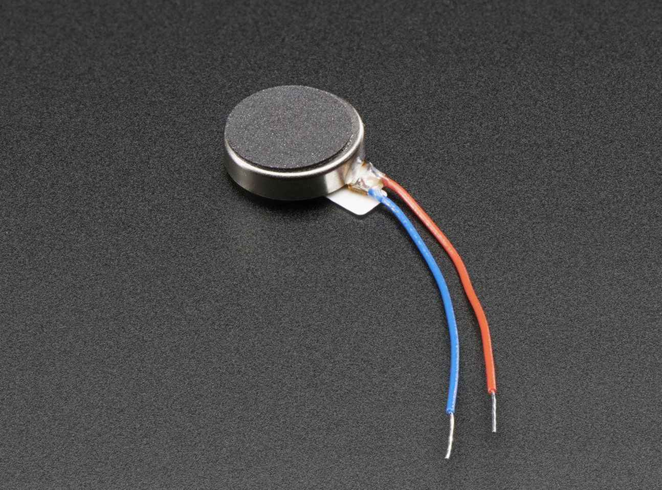
The MassageMe consist of a vest with 16 small buzzers (vibration motors) placed on the back that can be configured in various ways to provide different massages. The vibration motors are placed in a grid formation on the back of the vest to provide coverage to most of the user's back. We decided to use the Adafruit vibrating mini motor discs because they are flat and thus do not discomfort the user while wearing the vest. Additionally, the motors can be easily powered by a 2V - 5V voltage supply, which reduces the need for additional circuitry on the vest, making it easier to wear.
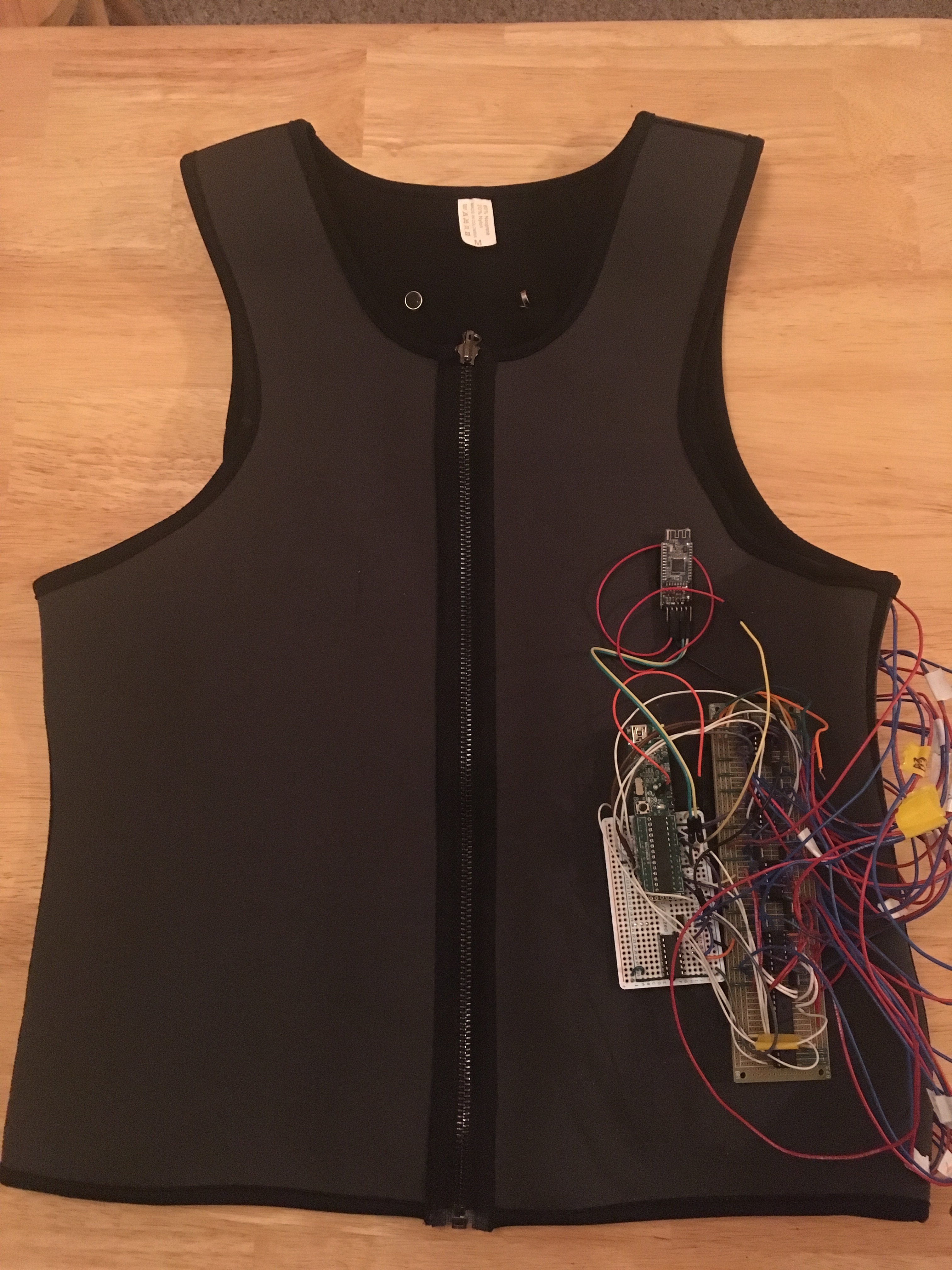
Vest Exterior
We wanted to have a user-friendly method of controlling the vest, which is why we decided to create a mobile application; iOS was chosen as the platform because all three of us have iPhones. In previous years, groups have been able to create Android applications to communicate with the PIC using the HC05 Bluetooth chip, but in our research, we discovered that the HC05 chip does not communicate with iOS devices. We decided to use the HM-10 Bluetooth chip because it can communicate with Apple's Core Bluetooth framework, and with the PIC.
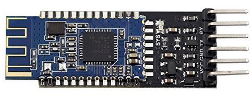
HM-10 Bluetooth Chip
The iOS Core Bluetooth framework supports several Bluetooth profiles. Additionally, the HM-10 is actually a Bluetooth Low Energy (BLE) chip; compared to traditional Bluetooth, BLE is able to consume less energy by remaining in sleep mode except when a connection is initiated. Connections themselves also only take a few milliseconds to establish, whereas for traditional Bluetooth, connections took hundreds of milliseconds to establish. This allows BLE to consume less energy than Bluetooth.
Hardware Design
To successfully fulfill the reflexology motivation behind the project, we decided that we needed to massage 16 different places on the back. These 16 places were divided into groups of 4, and placed in the upper-right, upper-left, lower-right, and lower-left regions of the back in locations that we determined would provide the most soothing and tension relieving massage. The devices used to carry out the message we decided to use were the Adafruit 1201 Vibrating Motor Disks. We selected these because they offered a variety of benefits: they could be powered using a voltage supply of 2V-5V, allowing us to power them using a 5V charger/USB connection and effectively controlling the vibration speed using a PWM signal; they at most consumed 100mA of current, meaning that we could power the entire circuit with a 5V, 2A rated power supply; and they were small, allowing us to easily sew them into the vest.
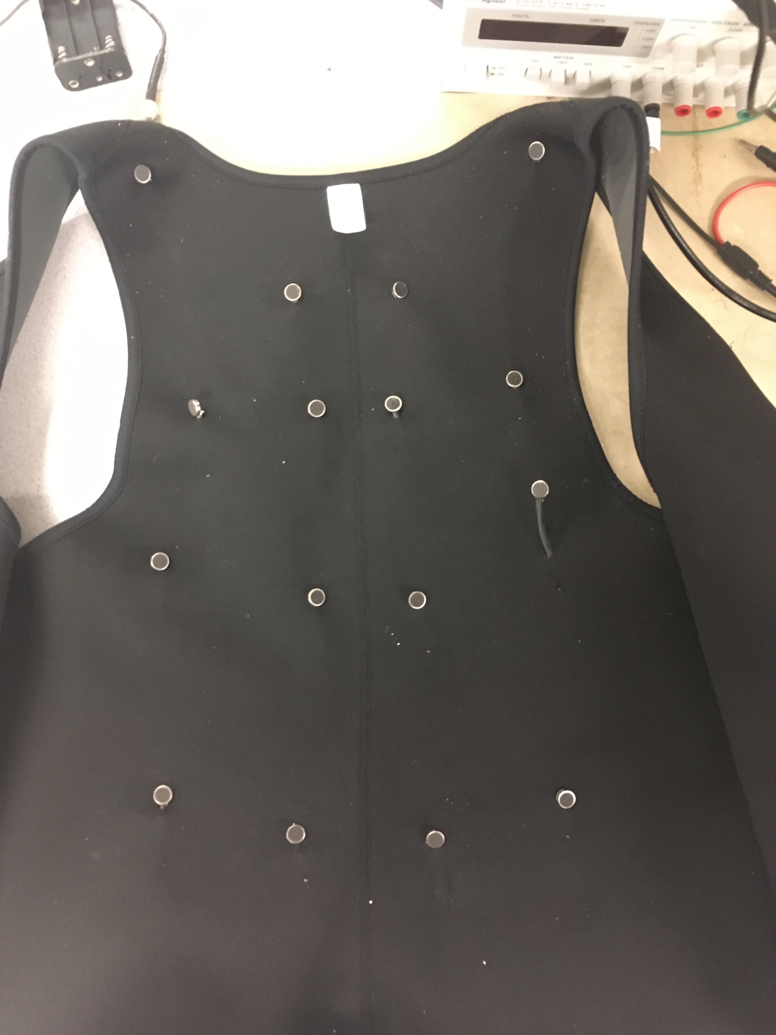
Vest Interior
The first challenge was determining how we would control the vibration intensity of the motors. We wanted to be able to this via software as opposed to using a potentiometer to control the voltage applied to the motors. Therefore, we concluded that this could be done using a PWM signal. Because the PIC32 could not support the amount of current required by the motors, the motors were connected to a separate 5V supply with the other end connected to the drain of a 2SK4017 NFET. The source of the FET was connected to ground, and the gate was connected to the inputted 3.3V PWM signal. The PWM signal successfully turned the FET on and off, allowing different average currents to flow through the FET and ultimately control the vibrating speed of the motor.
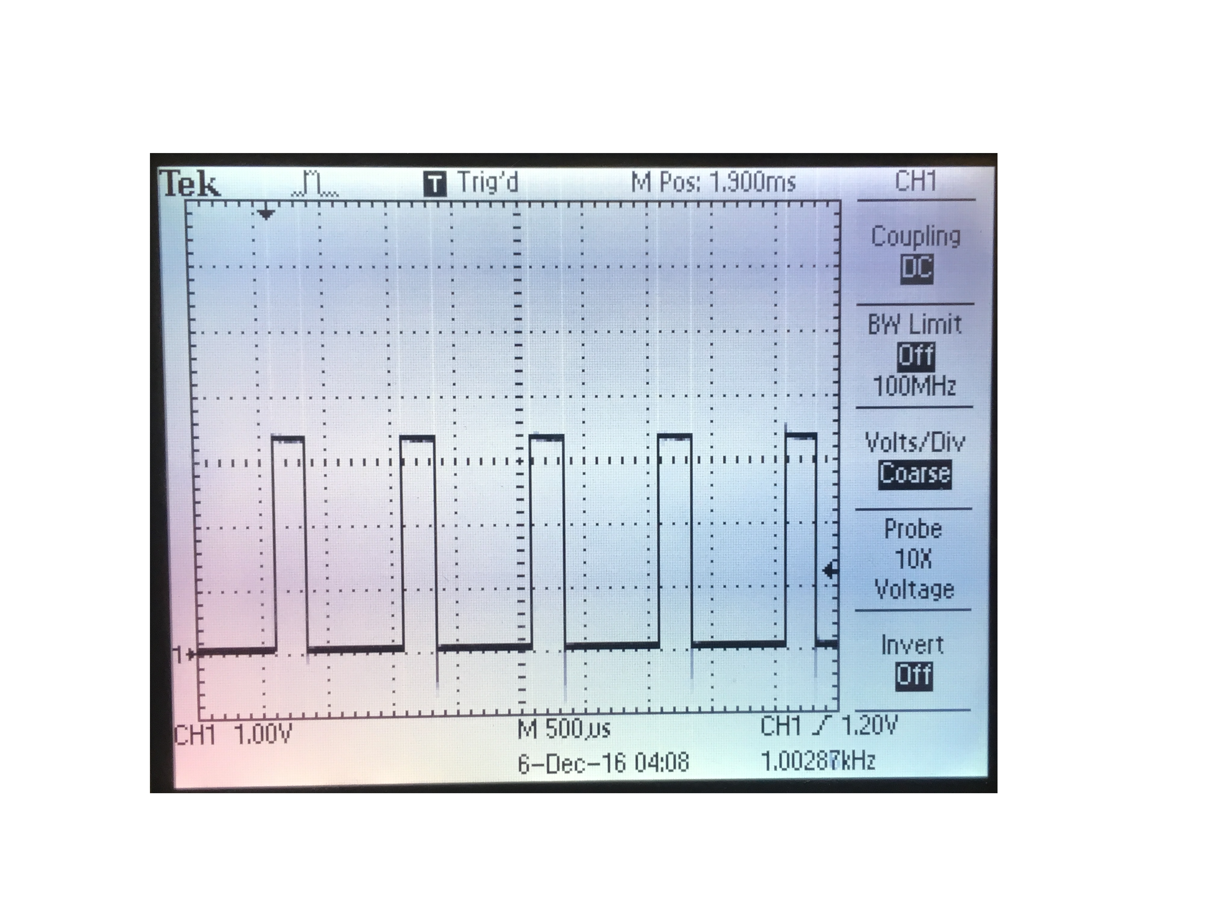
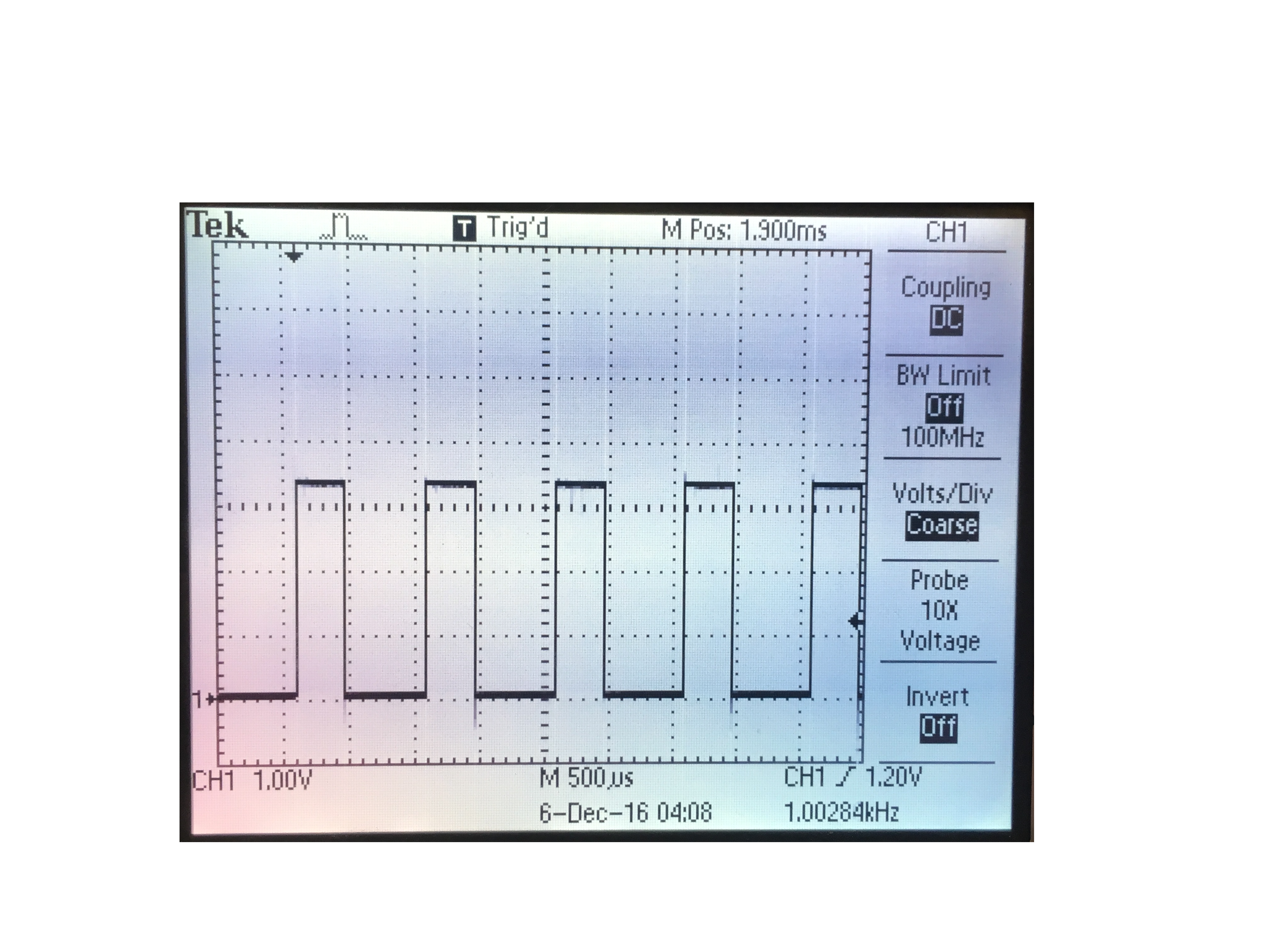
Next, we had to determine how we would control all 16 motors using PWM, as the PIC32 only offers five output compare peripherals. We decided that we would use four PWM channels, one for each region of the back. For each region, we used one 74L208 quadruple 2-input positive AND gate. This gate was selected because it was designed for the 5V power and 3.3V input logic levels we were using. Each PWM output was connected to all four B inputs to its associated AND gate. The A inputs were then port outputs from the pic. The Y outputs of the AND gate were then connected to the gates of the FETs. Using this implementation, the motors would turn on by setting its assigned pic32 port high, and its regions strength could be controlled using its specific PWM peripheral. A PWM signal and its corresponding AND gate output can also be seen below.
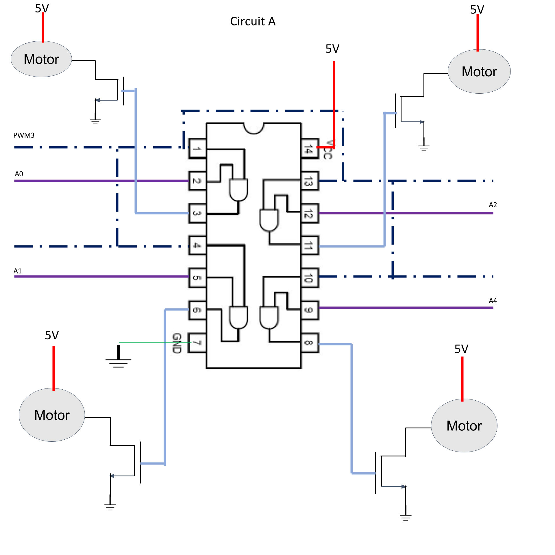
Vibration Motor Circuit
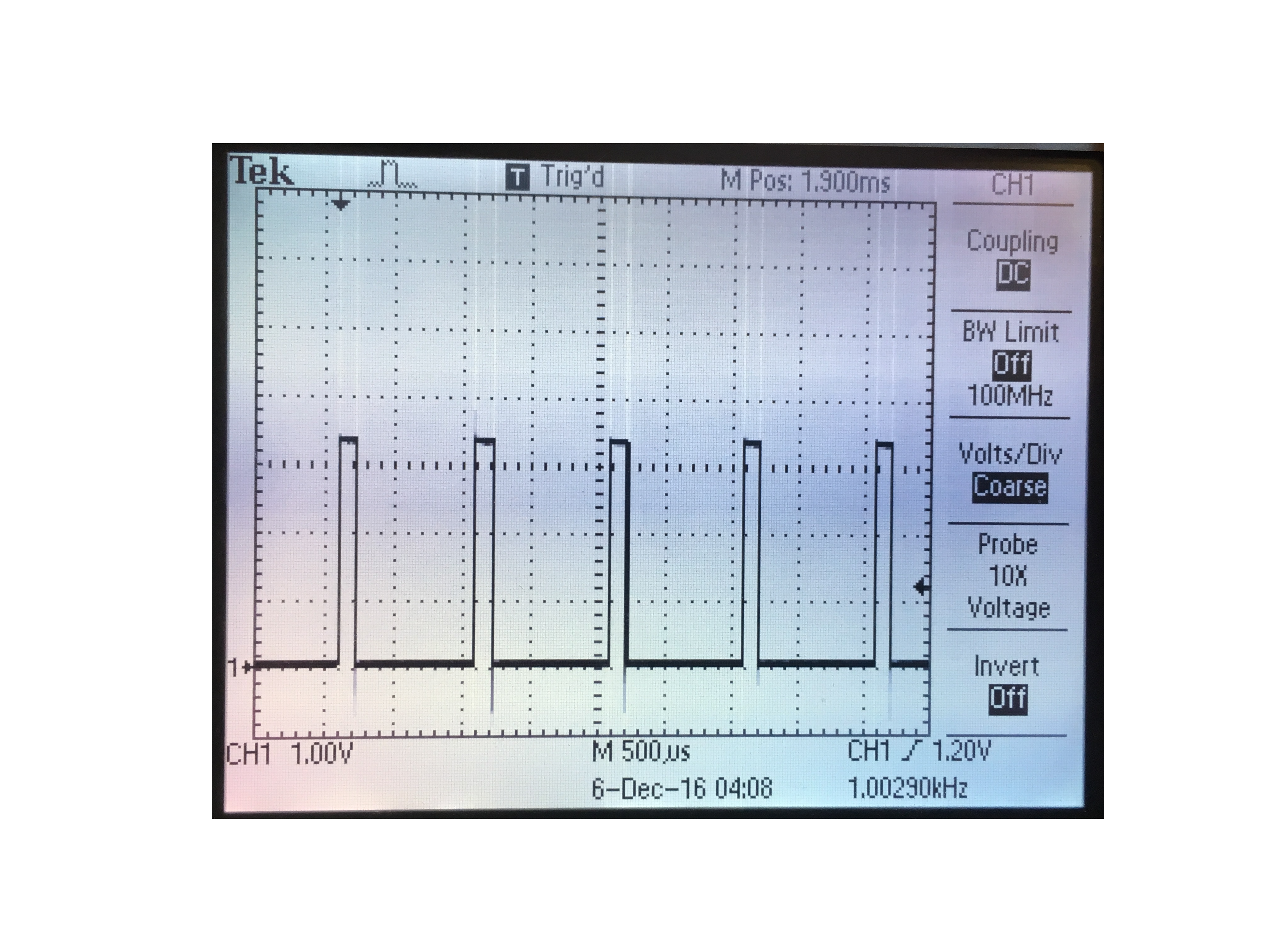
Low PWM Signal
AND Gate PWM Output
Because we wanted to implement 16 motors and there were only 13 available pins on the PIC32 after including the Bluetooth connections and PWM channels, we decided to use a MCP23S17 Port Expander. The Port Expander communicated with the PIC32 via SPI and provided 11 additional output pins, as it required 5 connections from the pic32. To connect and implement the Port Expander, we used the setup and libraries that Sean Carroll generously provided. For easy assignment, we divided the port regions into A, B, Y, and Z groupings. The upper-right region was controlled using the A0, A1, A2, and A4 ports on the pic; the upper-left region was controlled using the B0, B1, B3, and B4 ports on the pic; the lower-right region was controlled using the Z0, Z1, Z2, and Z3 ports on the port expander; and the lower-left region was controlled using the Y7, Y6, Y5, and Y4 ports on the port expander. Each of these groupings was all connected as A inputs to the same quadruple AND gate. If a motor needed to be turned on, its assigned port would turn high, and its vibration speed would be determined by the region’s PWM signal. Because we were experiencing difficulties with the B0 port, we later moved the B0 connection to Y3.
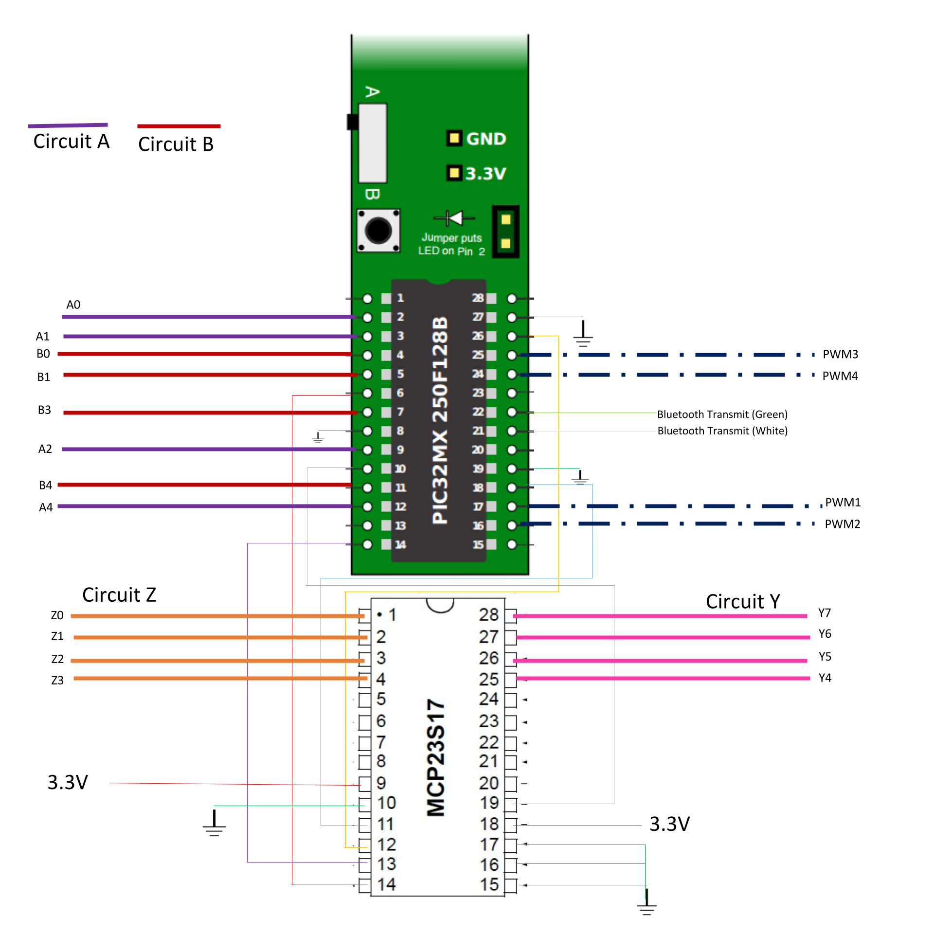
Port Expander Connections
Software Design
The software for this lab involved the Bluetooth communication between the iPhone and the HM-10 Bluetooth Low Energy (BLE) module, and the UART serial communication between the HM-10 module and the PIC32. The HM-10 essentially functions as an intermediary between the iPhone and the PIC32, transmitting the information it receives from the iPhone serially to the PIC32. A complete zip file of all the code can be found in Appendix B.
The application for the iPhone was designed as an iOS app in the Swift programming language. Xcode was used for development. We used Apple’s Core Bluetooth framework to manage the backend communication between the iOS app and the HM-10 module. We also used a Bluetooth library provided by Alex Hoiberg on Github to rapidly develop our Bluetooth methods. In addition to providing Bluetooth serial methods, Hoiberg’s HM-10 Bluetooth Serial iOS app was critical to testing the initial connection of the iPhone to HM-10 module before we had developed our own app.
In a Bluetooth low energy connection, there is a central player and a peripheral player. The central generally receives services from the peripheral and performs actions based on the received information. In our case, we chose to make the iPhone the central device and the HM-10 module the peripheral, as this allowed us to minimize the complexity of the iOS code.
Before we incorporated the HM-10 into the project, we had to change some its default settings using the AT commands described below. Notable changes from the default settings are as follows: we decided to have it advertise every second to save power, we turned on notifications in order to use it with the iOS application, and we turned on battery monitoring to make it more user-friendly. The commands are entered via the serial terminal, and these settings only have to be configured once.
AT+ADV8 - advertises every second
AT+ADTY0 - advertising & scan response & connectable
AT+ANCS1 - notifications
AT+BATC1 - battery monitoring is on
When the app is first opened, it must connect to the HM-10 module. The connection is shown by the screens below. The app was designed to support the three modes of operation: Preset, Custom, and Draw. The home screen of the app allows the user to navigate to one of three modes, as shown in the images below.
Loading Screen
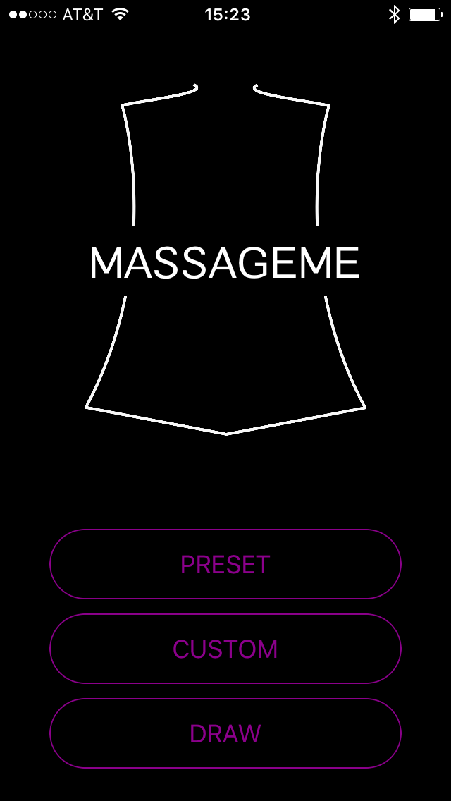
Main Screen
In Preset, mode, the user has the option of four preset massages. The options are Full Back, Upper Back, Lower Back, and Spine. As the user scrolls through the options, a visual is displayed showing which vibration motors correspond to each setting. Once the user has made her choice, she can press the Start massage button. Each preset massage corresponds to a pattern saved on the PIC32. The massage pattern continues until the user chooses to stop the massage by pressing the Stop massage button on the app. The app’s behavior for Preset mode can be seen below.
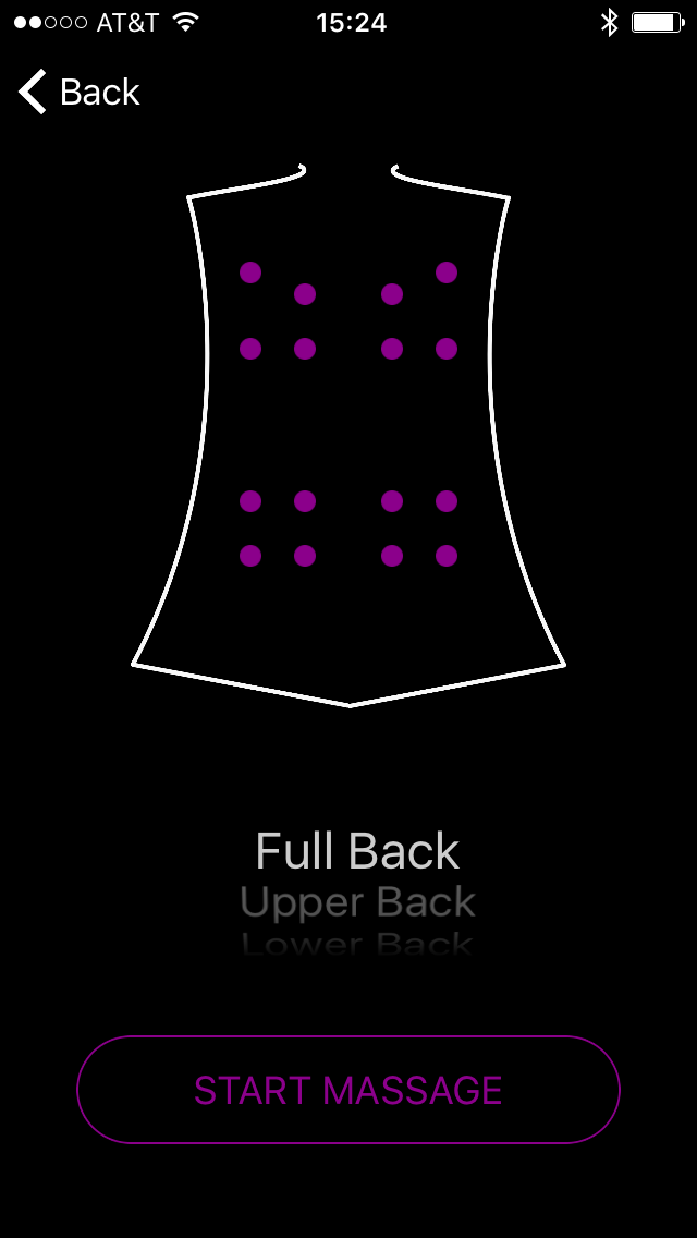
Full Back
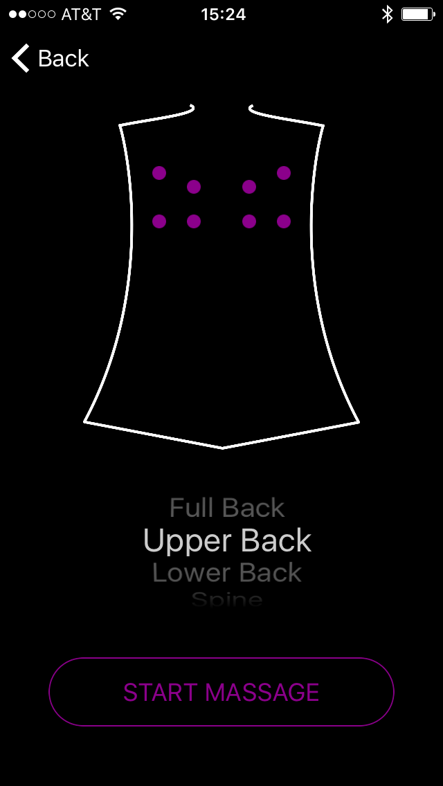
Upper Back
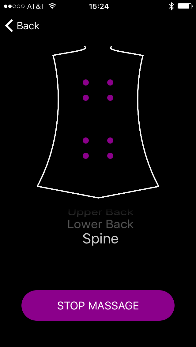
Spine
In Custom mode, the user has more flexibility to customize her massage experience. The user specifies which region(s) to turn on by tapping the region. The strength of the region is also chosen based on the number of taps on the region, rotating through three strength options before the region turns off again. Once the user has made her initial choices, she can start the massage. The user can update her preferences for any of the regions during the massage, by simply tapping on the region to be changed. When the user wants to stop the massage, she can press the Stop button as before. The app’s behavior for the Custom mode is shown in the images below.
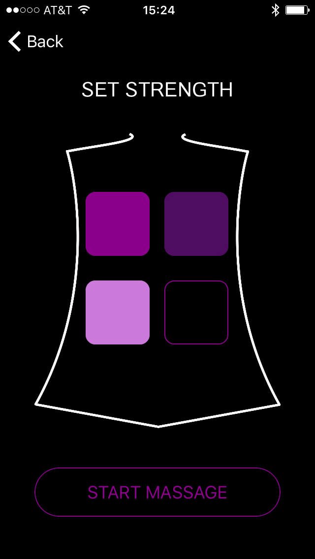
Custom Start Massage
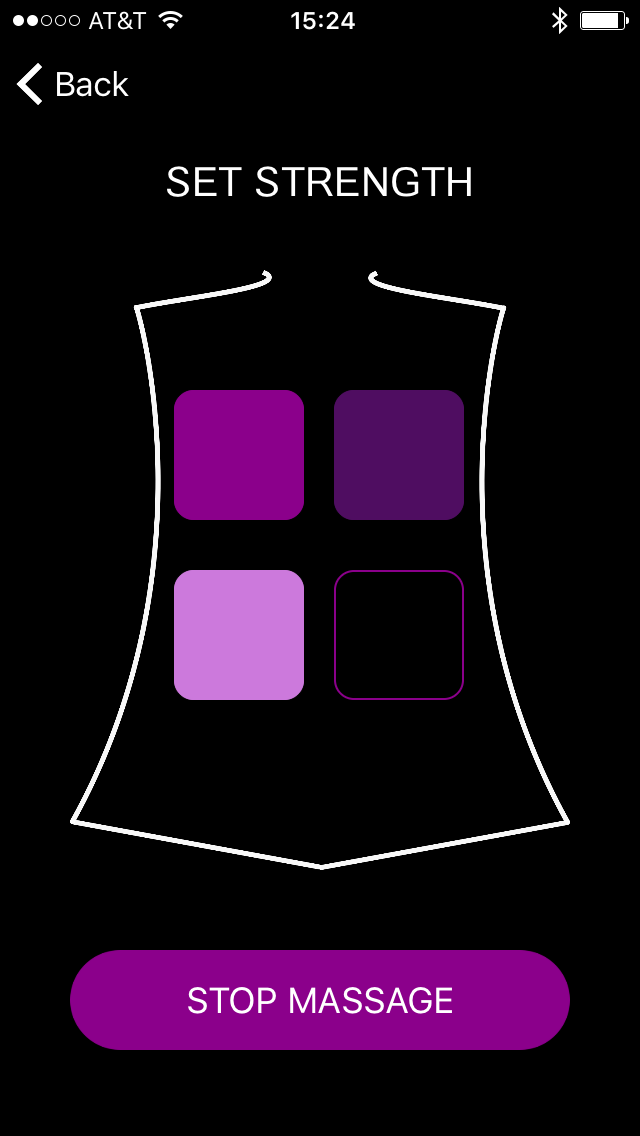
Custom Stop Massage
In Draw mode, the user has the opportunity to draw a pattern for the massage to play. The user specifies the vibration motors she wants on, and the vibration motors turn on for one second each in the order the user requests. Once the pattern is complete, the user can enter a new pattern to play. The pattern can also be reset as the user is entering it by shaking the iPhone. As in the other designs, the user can stop the massage at any point during the massage by pressing the Stop button. The Draw mode is demonstrated in the figures below.
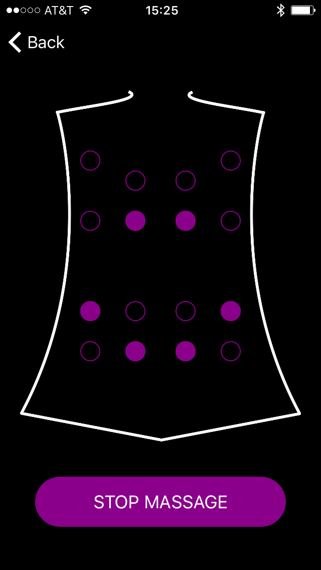
Draw Mode
In order to send the user’s choices to the HM-10 and PIC32, we define a MassageMe protocol. The protocol is shown below in Figure ?. There are four different types of messages that can be sent from the iOS app to the HM-10. The messages are sent as UInt8 byte arrays and are terminated with an EOT character. The type of message (preset, custom, or draw) is indicated as the first byte in the message. A Preset message must also include the type of massage (full back, upper back, lower back, or spine). A Custom message must include a strength for each of the four regions, where the strength ranges from 0 to 3, with a 0 indicating off. A Draw message is of varying lengths depending on how many vibration motors a user selects. As a user selects a vibration motor, the number associated with the vibration motor gets added to the message. The final type of message that can be sent the PIC32 is a Stop message when the user wants to stop a massage. There is one type of message for communication from PIC32 to iOS app. This message is a Reset message and is only used in Draw mode when the PIC32 completes playing the pattern on the vibration motors. This message allows the user to set another massage once the drawing is done. The other modes do not require this message as they run continuously until the user chooses to end the massage from the iOS app.
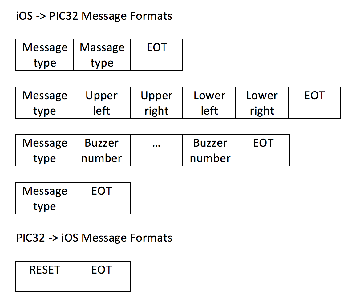
Message Formats
The PIC32 is responsible for receiving the messages from the iOS app via the HM-10. We developed the code for the PIC32 using MPLAB and the Protothread library. We used four different threads - one thread to receive Bluetooth serial data from the HM-10 and one thread for each of the three operational modes. Our schedule runs the threads in a round-robin order,where the threads must yield to one another to give up the CPU, as we use non-preemptive scheduling. The Bluetooth thread yields until data is available, and then receives data until it hits the EOT character. The first data byte is then read to determine the type of message, setting a flag for the appropriate thread if the message indicates the start of a new massage, or stopping the currently running massage if the message is a Stop message. If the message is a Preset message, the Preset thread reads the next byte of the message to determine the type of preset. Depending on the type of preset, the vibration motor regions are turned on and the strength for the regions alternates every two seconds by changing the PWM to those regions to generate a comfortable massage. If the message is a Custom message, the Custom thread reads the value for each region, turns the vibration motors on for the region if the strength is greater than zero, and sets the PWM for each region to correspond to the strength. If the message is a Draw message, the Draw thread iterates through each byte in the message, turning on the vibration motor for one second. The Draw thread was the more challenging thread as it had to map the numbers in the message, which range from 0 to 15, to particular vibration motors on the vest. The mapping was accomplished through co-design with the hardware. The vibration motors are divided into four groups where each group was associated with a pin grouping (A, B, Y, and Z). In terms of software, the bits to be set within the pin grouping are arranged into four arrays corresponding to each pin grouping. The number for the vibration motor in the serial message is first mapped to a pin grouping array, and then mapped to an index within the array to determine which bit to turn on for a particular vibration motor number. The Draw thread also has the added complexity that it can complete its task unlike the other massage threads. Once Draw thread sees the EOT character, it stops the constant digital output to the vibration motors, turns off the PWM signals, and sends a message back to the iOS app via the HM-10.
Since we wanted to offer the user the feature of turning off the massage whenever they wanted, we had to make sure that the PIC32 could receive a Stop message at any time. Thus we had to make sure our massage threads yielded so that the Bluetooth thread could continually receive messsages. When a Stop message is received, the PIC32 disables the flag for the running massage and turns off the vibration motors.
Testing & Results
Most of the testing and debugging of MassageMe ocurred while integrating the hardware and the software on the final protoboard. We noticed that the final circuit was very sensitive to changes in current, to the point where setting one vibration motor on full strength would trigger all the other vibration motors on the vest to turn on. We concluded that this was the result of the brownout behaviour discussed later in this section. Our solution was to decrease the duty cycle of the PWM signal going through all the vibration motors in order to decrease the overall current going through all the vibration motors. This had the desired effect of not having any one vibration motor turn on the rest of the vest when it was not supposed to, and the const of decreasing the maximum intensity of the vibration motors. The duty cycles of the final PWM signals used for high, medium, and low vibration motor settings can be seen below:
Low PWM
Medium PWM
High PWM
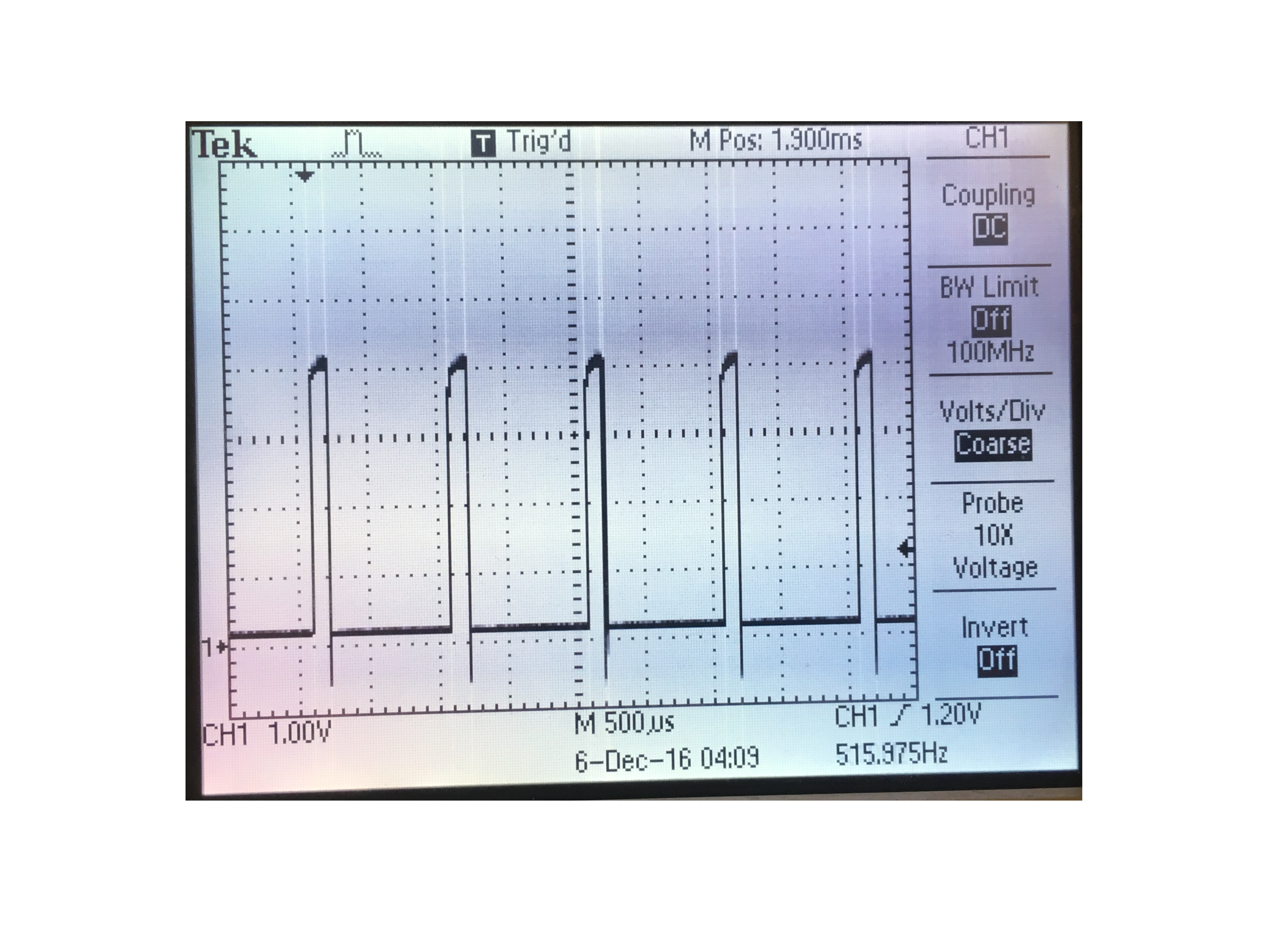
The biggest challenge that we faced for the hardware portion of the project was scaling up the number of motors. Every time we added more motors, undesired behavior occurred in the form of large voltage spikes and periodic dips in the 5V power supply (see scope image below). This would in turn cause the port expander to act strangely, turning on all of its connected motors which could not be turned off unless the program was reset.
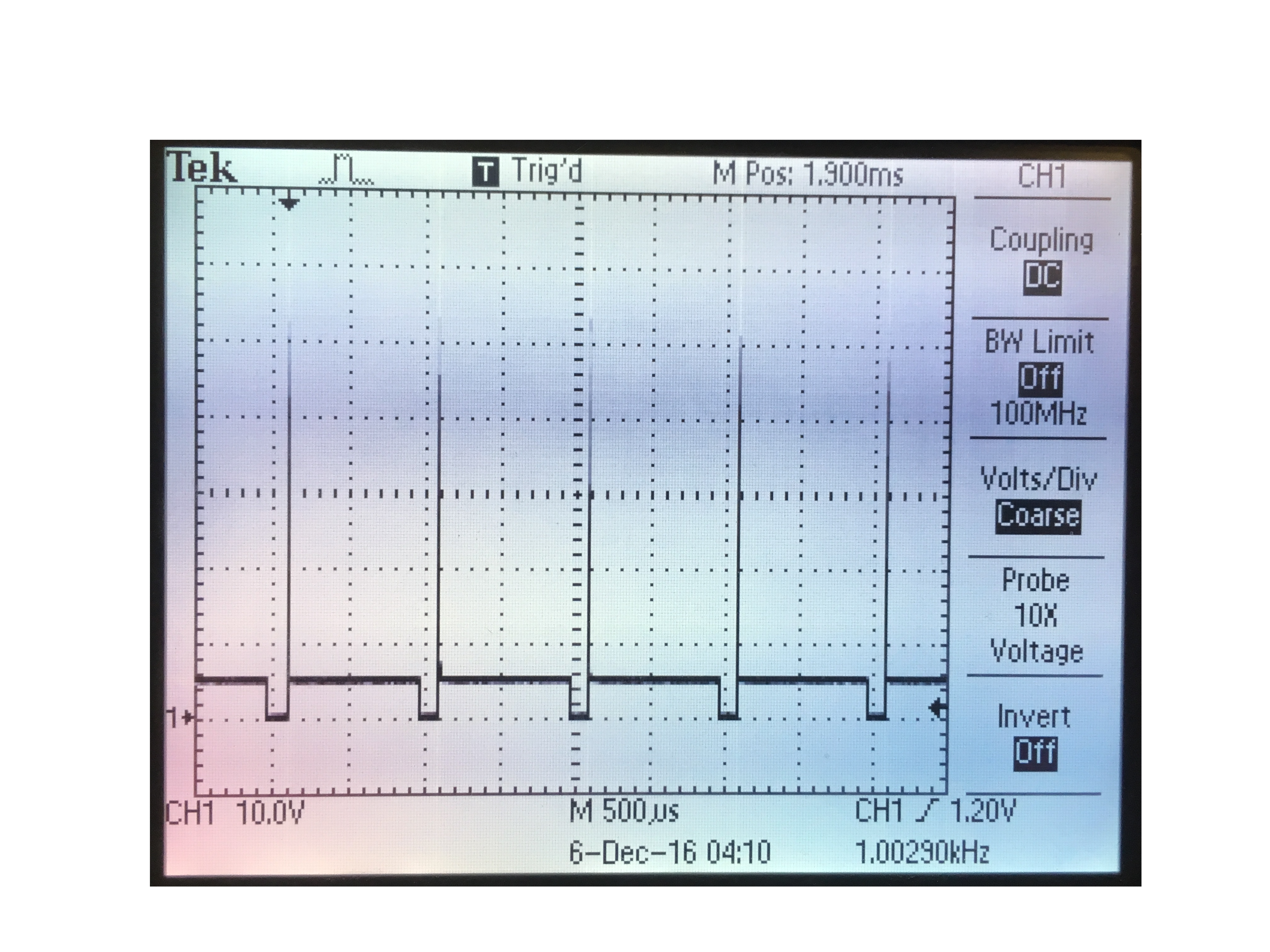
Voltage Spikes
This behavior appeared to be brownout behavior, which is a dip in the power supply that causes unreliable behavior. We believe that the behavior we observed was a result of the brownout behavior affecting the AND gates, as apart from the motors those were the only circuit components connected to the 5V supply. This in turn resulted in the connected Port Expander to malfunction. The pic32-connected motors did not fail because the pic32 is built to be able to handle certain levels of brownout. As well, in extreme cases, the pic32 will self-reset if the brownout condition reaches critical levels and becomes dangerous for the circuit.
To accommodate for the brownout behavior we reduced our maximum PWM signal and therefor the maximum average current and vibration of the motors. This reduced the amount of voltage spike on the 5V supply; however, we were not able to attain the highest level of massage that we desired. If we were to improve upon our design to handle brownout better, we would aim to completely isolate the PIC32, port expander, and gates from the rest of the circuit powered by the 5V rail powering the motors. This could be done using opto-isolators. That PIC32, port expander, and gates could be connected to one end of the isolators, and the other connected to the motor part of the circuit. This would allow us to run more current through the motors without affecting as much of the circuit, and would allow us to turn off and on the port expander without resetting the PIC32.
Another issue we noticed in our final design is that different vibration motors deliver different intensities with the same PWM output. This is due to the design variation of the motors; they consume slightly different current amounts when supplied with the same voltage.
Given that the MassageMe vest can draw up to 1.3A of current at full power, and that this is something the user will be wearing, safety was at the forefront of every design decision we made. The design's most significant point of weakness is at the connection between the vibration motor's leads and the copper wires used to connect the vibration motor to the protoboard. Because this solder connection was incredibly weak, it was reinforced with two layers of heat shrink tubing. Initially, we thought copper wires would be too stiff and affect the fit of the vest on the user, so we tried to use confductive thread to connect the vibration motors to the control circuit. However, we quickly realized that since conductive thread is not insulating, if the user every powers on the vest and folds it in such a way that both leads of the vibration motor are touching one another, the vest will catch on fire. Hence, we decided to use insulated copper wires.
BLE operates in the 2.4GHz frequency range, thus there might be some interference if there are other devices within very close range of MassageMe also operating in the same frequency band. Additionally, only one BLE device can be paired with an iOS device at the same time, so if the user is already using another BLE peripheral with their iOS device, they cannot use MassageMe.
The vest used to build MassageMe is a men's size medium compression vest, so anyone able to wear the vest should be able to use MassageMe.
When observing other students try on the vest, one thing we noticed was that everyone enjoyed using the mobile application interface to control the vest. A recurring comment we got was that the vest itself physically did not fit anyone well at all, and people often had to tug on it to hold it in place to feel the vibration motors. If we were to pursue this in the future, an option we would definitely consider is perhaps simply having a thin 'sheet' of vibration motors that users can stick inside whatever item of clothing fits them most snugly in order to obtain the optimal massage.
Conclusion
The goal of this project was to build a massage vest that could be easily used for reflexology and relaxation purposes. We were able to meet this goal by creating an application which allowed users to select the type of massage they wanted at the push of a button. However, there are several aspects of MassageMe that we would change if we were to work on it further, and if we decided to potentially take it to market.
Ideally, MassageMe would have a portable power supply - right now it is powered by the DC power supply on the lab bench. When deciding how to power the vest, we assumed portable phone chargers with the correct current specification (can output > 1.5A) would be able to power the vest. However, we didn't account for the fact that phone chargers automatically turn off if no current is drawn from them - thus, every time none of the vibration motors were on, the charger would automatically switch off (the charger did not have a button to turn it on). There are two solutions to this problem that we can implement for future use: we can either use a phone charger that has a button to turn it on, or we can use a voltage regulator to step down 4 AA batteries to output 5V instead of 6V.
The existing circuit setup used to control the vibration motors has close to 50 long wires coming out of it, and it's located near the user's left arm, which makes the vest a bit unwieldy to wear. In the future, we would definitely make a PCB of the vibration motor control circuit. Not only would this make the circuit easily replicable, it would also make the vest more comfortable to wear, since the PCB's smaller dimensions would allow it to be placed in a more user-friendly location on the vest.
Given that MassageMe already interfaces with an iPhone using the MassageMe application, additional iOS services can be incorporated into the application. For instance, if the user has an Apple Watch, heart rate data can be used to change the settings in the MassageMe app in a way such that the massage vest can increase or decrease the user's heart rate. Another change that can be incorporated into the application is the ability for users to save custom massage settings.
There are a few similar massage vest prototypes that currently exist. One of them was undergoing development at Cornell a few years ago, but there didn't appear to be an immediately obvious way of controlling and adjusting the settings on the vest. Another vest we encountered in our research only massaged the neck, and not the back, but it did have iOS controls. None of these vests appear to have obtained a patent yet, thus we are not infringing on any intellectual property.
The code for MassageMe has incorporated open-source code and we have credited the authors of that code accordingly. Specifically, Alex Hoiberg's Bluetooth Serial application laid the foundation of the Bluetooth connection code, and Sean Carroll's port expander library was used on the PIC side to increase the number of pins we could use.
When building MassageMe, we took the necessary precautions to ensure that our decisions and final design were consistent with the IEEE Code of Ethics. Our first concern was to not copy, steal, or infringe on any past similar products or designs, in accordance with point 2 on the IEEE code of Ethics. We did a lot of research to make sure that no similar product was on the market and that we were not pursuing the work of others. What we found was that there was no mobile-controlled massage vest currently on the market. Furthermore, the product that most closely resembled our idea was a massage developed by past Cornell students, however their designs were completely different than ours, as they used different technologies such as piezoelectric cells and cell-phone vibration motors that our product did not use. Our next considerations abided with points 1 and 9, which was to ensure the safety and well-being of the users of the product. We confirmed and tested that every electrical component used would function properly in the given environment, and that the materials attached to the piece of clothing would not cause any fire or electrical shock to the user. We also made sure that our design process followed points 3, 5, 6, and 7. When discussing our idea in the early planning stages, we made sure that the goal would be challenging but reasonable, fall within our technical expertise, and make a contribution the engineering community. Throughout the process we were not hesitant to seek out advice, and were always willing to provide advice to others. Lastly, we made sure to follow points 4 and 8. No instances of bribery occurred, and our product was usable and available to all persons, regardless of their race, religion, gender, disability, age, national origin, sexual orientation, gender identity, or gender expression.
Appendix A
The group approves this report for inclusion on the course website.
The group approves the video for inclusion on the course YouTube channel.
Appendix B - BOM, Code & Schematics
Appendix C - Open-Source Code & Datasheets
Appendix D - Work Distribution
Megan wrote the iOS application code and integration code between the iOS application and the PIC; she also wrote the software section of the website. Harry designed and debugged the circuit, got the port expander working, and wrote the hardware section, ethics paragraph, and BOM. Gargi debugged the circuit, soldered the components necessary for the vest, and put together the rest of the website.
Appendix E - Miscellaneous Resources