"Two Channel Polygraph Machine"
Project Sound Bite
Ask a group of people what a polygraph is and the most common answer you will receive is that a polygraph is a lie detector. But is it really? Contrary to common opinion, a polygraph will not give you a yes or no answer if you are lying or telling the truth. The polygraph is a combination of sensors that measure your body's response to various questions. Often times, a subject's heart rate, galvanic skin response, blood pressure, and breathing rate will be measured. Depending on how advanced the machine is, there could be more or less data taken. This data is then analyzed by a trained polygraph examiner who determines whether a particular question is causing a certain body response because you are being deceptive or for other reasons. The process of determining whether or not someone is lying is a lot more involved and complex than just being hooked up to a machine and can take up to three hours per session. For our final project we decided to build an old fashioned polygraph machine. Our polygraph measured one's heart rate, and breathing rate. All of the data was fed into the PIC32, processed, and then drawn on a piece of paper by servo controlled “needles”. The waveforms were also displayed on a TFT display. Modern polygraphs connect to a computer and utilize programs similar to Matlab to plot and analyse the data in real time. Our polygraph is more of a relic as it is a replica of machines used before computer data analysis became the standard for polygraph examinations.
Polygraph Machine
High Level Design top
Rationale and Sources
The idea for our project came from past experiences with polygraph examinations. We were curious to see if we could build such a machine from scratch.
Hardware/Software
As mentioned above, we tested heart rate, and breathing rate. To measure heart rate we built an ECG. In order to measure the breathing rate we used a stretch sensor connected around our diaphragm and measured the voltage changes across it as we breathed. These two circuits fed into the PIC32 ADC. The code for the PIC32 then processed the data and converted each output from the analog circuits into a form that allowed the servos to rotate to the correct angle to draw the waveform. We also had an additional servo that rotated a roll of paper onto which the servos drew the waveforms. Additionally, we included a colored TFT display that displayed the ECG and stretch sensor waveforms in real time.
Logical Structure
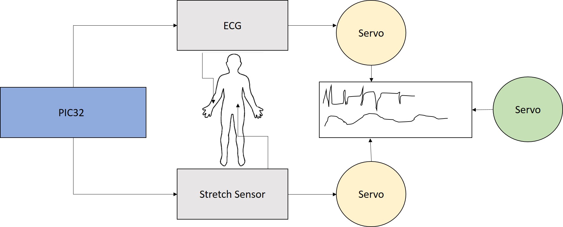
The PIC32 takes data from the ECG circuit and Stretch Sensor, which are attached to a person. The servos then take the data from the PIC32 and translate that onto paper, which is being pulled by another servo.
Standards
In the ANSI standards, there is ASTM E2031-99, otherwise known as Standard Practice for Quality Control of Psychophysiological Detection of Deception (Polygraph) Examinations. This standard states the purpose of polygraph as, “This practice establishes essential and recommended procedures for the conduct of quality control for a Psychophysiological Detection of Deception (PDD) examination.” Since we are creating a polygraph machine our purpose is the same as the one listed in this standard; however, we will not be interpreting our results to actually detect deception.
Existing Patents and Papers
Polygraph machines have been produced and used by many organizations and companies before. They are also widely available for purchase.
Hardware Design top
The project hardware consisted of an Adafruit TFT LCD display, PIC32, stretch sensor, differential amplifier, and servos. A large part of our project was analog. We had to build the stretch sensor circuit, the ECG, and the PWM circuits for the servos using components available in lab. The circuit schematics will be described in more detail below. The most challenging circuit we had to build was definitely the ECG because it was the most complex circuit in our project, we had difficulty finding capacitors and resistors of the desired values, and there was a lot of debugging involved because the body produces a lot of noise. Images of the final circuits are shown below.

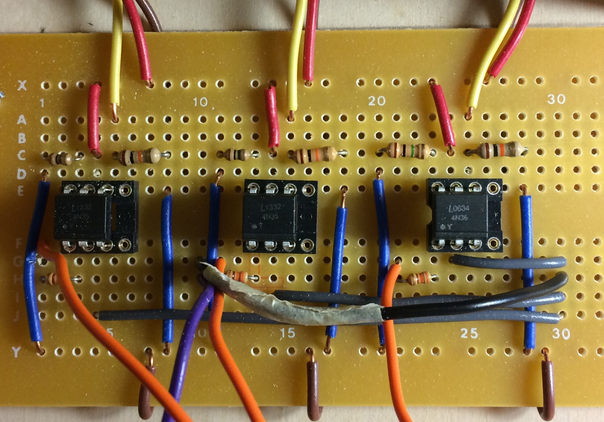
Electrocardiogram Circuit with Stretch Sensor Circuit
PWM Circuits
Stretch Sensor
The stretch sensor we used was a conductive rubber cord approximately three inches in length. When the chord was not stretched it had a resistance of 1kΩ and when put under tension the resistance increased to at most 10kΩ. In order to measure a person's breathing rate, we wired the sensor in series with a 56kΩ resistor and connected it to +12V. A shoelace was then wrapped around the diaphragm of the person taking the polygraph. The ends of the shoelace were connected by the stretch sensor so that as the person breathed in and out the rubber cord was stretched and released. Another wire was connected from one side of the stretch sensor to an analog pin on the PIC32 so that the voltage across the sensor could be inputted into the PIC in real time. Both the amplitude and frequency of the resulting waveform varied based on how the person was breathing. Short rapid breaths resulted in a high frequency but lower amplitude waveform while deep breaths resulted in a waveform with larger amplitude. The circuit schematic is shown below.
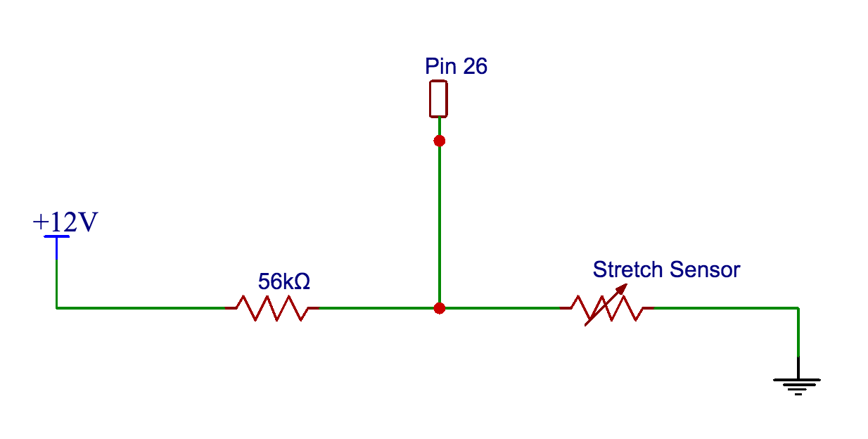
Stretch Sensor Circuit Schematic
Electrocardiogram
The electrocardiogram circuit utilized various resistors, capacitors, two LM358 operational amplifiers, an INA116 differential amplifier, and a diode. Our initial ECG circuit design was based off of the circuit schematic used by Sean Hubber and Crystal Lu in their “Hands on ECG”project; however, we had to make several modifications to their design because we were measuring heart rate by attaching electrodes to our wrists and we used a PIC32 for our data processing. The final circuit schematic we used is shown below.
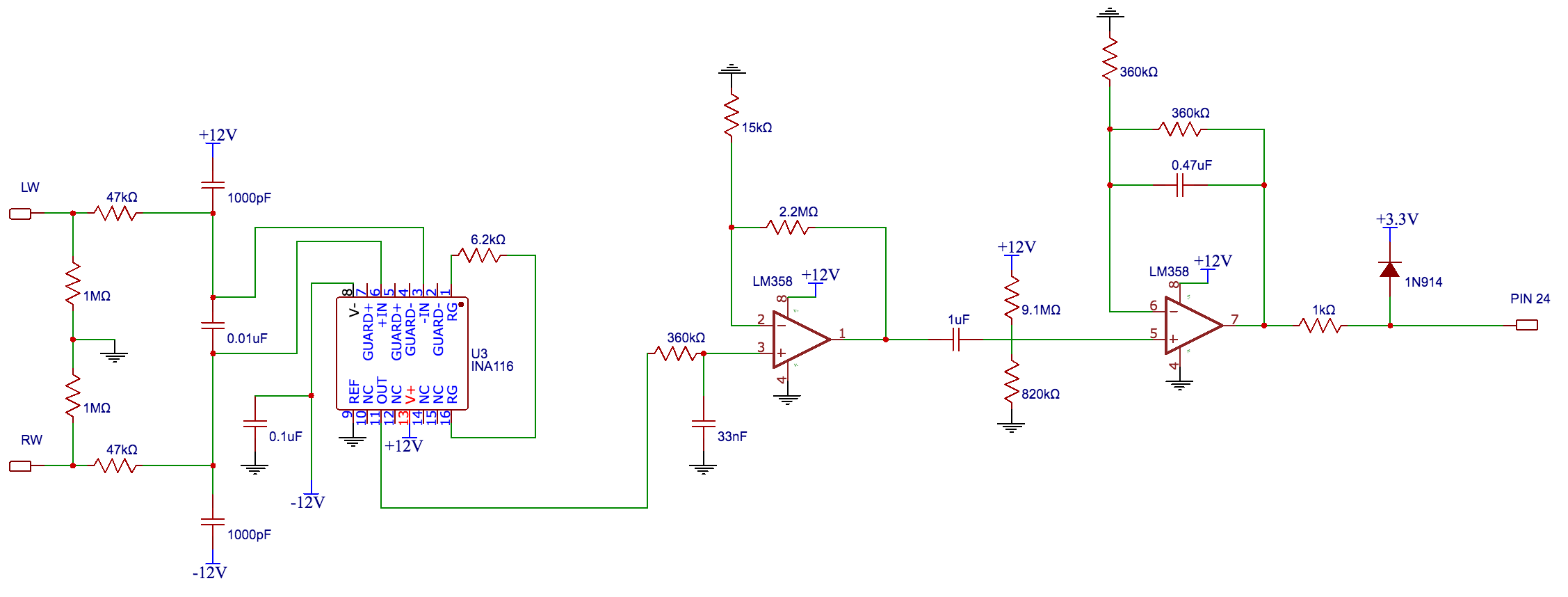
ECG Circuit Schematic
The first stage is a combination of resistors and capacitors. The purpose of this stage is to ensure user safety through DC isolation. After the signal passes through the DC isolation stage it is fed into an INA116 differential amplifier. We used a resistor (Rg) with a value of 6.2kΩ across pins 1 and 16 to give us a gain of 1+(50kΩ/Rg)=9.06. We required a large gain because the signal coming from body was on the millivolts magnitude. The next two opamps that the signal was sent through were filters with additional gain that amplified the signal even further. The first opamp stage was a low pass filter with the purpose of filtering out 60 Hz noise. The second filter was used to eliminate DC offset. Then the output of the last opamp was fed into a voltage limiter circuit that was a combination of a resistor and a diode. The voltage limiter circuit prevented over +3.3V from entering the PIC32 pin and burning the microcontroller.
TFT
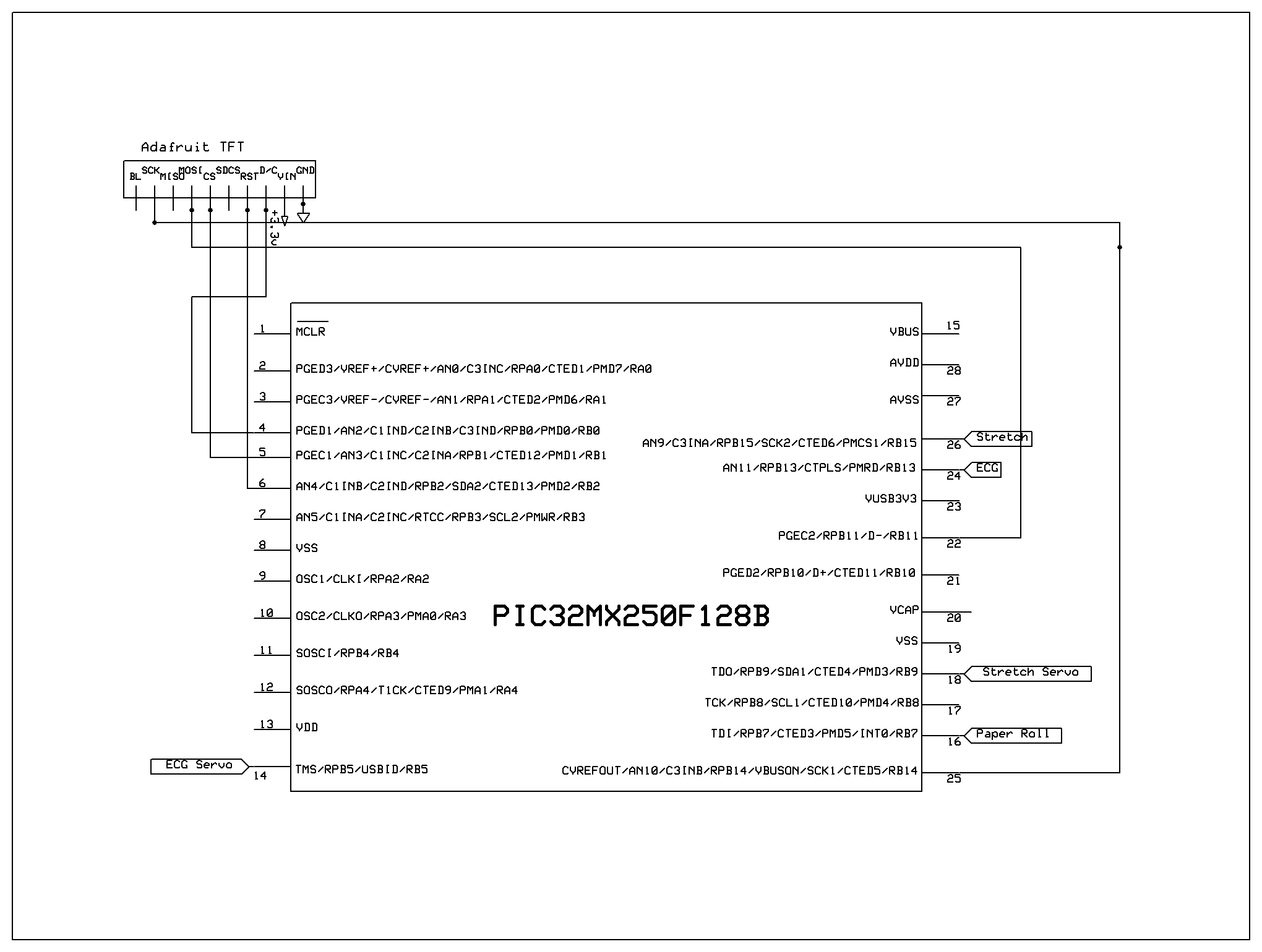
We wired the TFT display to the microcontroller using the instructions on Syed Tahmid Mahbub’s blog and the PIC32 datasheet. The TFT display used pins 4, 5, 6, 22, and 25 of the PIC32 microcontroller. The exact mapping of the pins is listed below.
CK: connected to RB14 on the PIC (pin 25)
MOSI: connected to RB11 on the PIC (pin 22)
CS: connected to RB1 on the PIC (pin 5)
RST: connected to RB2 on the PIC (pin 6)
D/C: connected to RB0 on the PIC (pin 4)
VIN: connected to 3.3V supply from PIC32
GND: connected to gnd
Servos
Each servo was connected to a pin on the PIC32; the servo drawing the ECG waveform was connected to pin 14; the servo drawing the stretch sensor waveform was connected to pin 18, and the servo controlling the paper roll was connected to pin 16. Attached to each rotor head was a wooden stir stick that had the tip of a pencil glued to its end. As the servos turned they moved the pencil tip along the paper and drew out the waves created by the different circuits.
On the other end of the polygraph machine we had a modified servo (continuous rotation servo) that pulled a roll of paper at a specified speed. Originally, we had designed this part of the polygraph machine using a DC motor, but when we modified the speed of the motor to slow it down, it did not have enough torque to pull the paper.
The circuit schematic we used to control the servos is shown below. We used a 4N35 optoisolator in order to completely isolate the PIC32 from each servo. The servos were all powered off of a +5V power supply. Since we had three servos we built three of the circuits seen below, one for each servo.
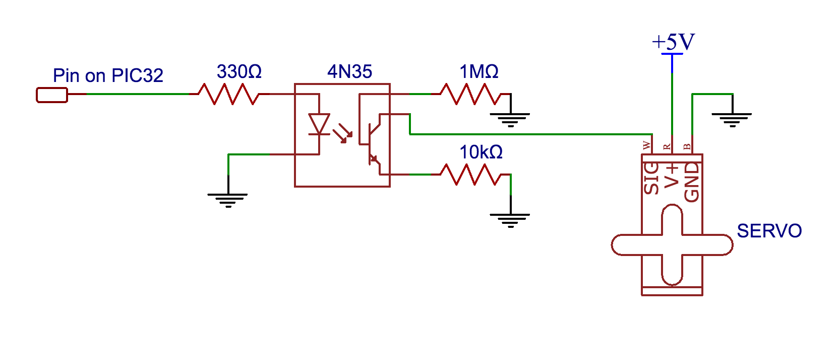
Circuit Schematic for Servo Control
Power Supply
In total we used two power supplies. One to power the ECG and the stretch sensor circuit, and another to power the servos. The servos used +5V, the ECG used +12V and -12V, and the stretch sensor circuit also used +12V. There was a common ground between the PIC32 and the +12V power supply. The PIC32 was powered via USB connection from our laptop which was not connected to a wall socket for safety reasons.
Physical Structure
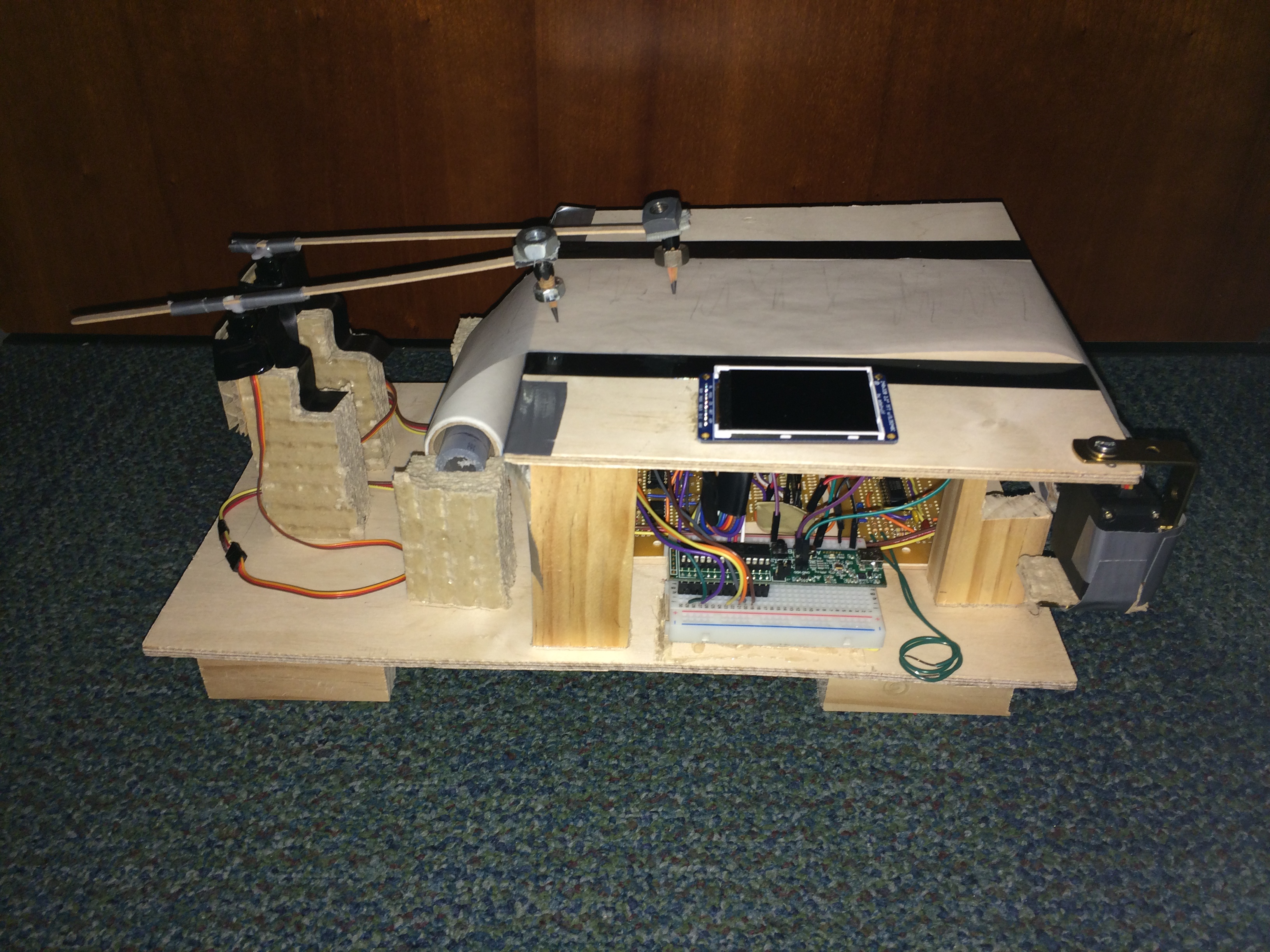
The physical structure of our polygraph was built out of wood and cardboard. All of our circuits were soldered with the exception of the bread board on which the PIC32 was connected. The final result is shown below.

Polygraph Machine
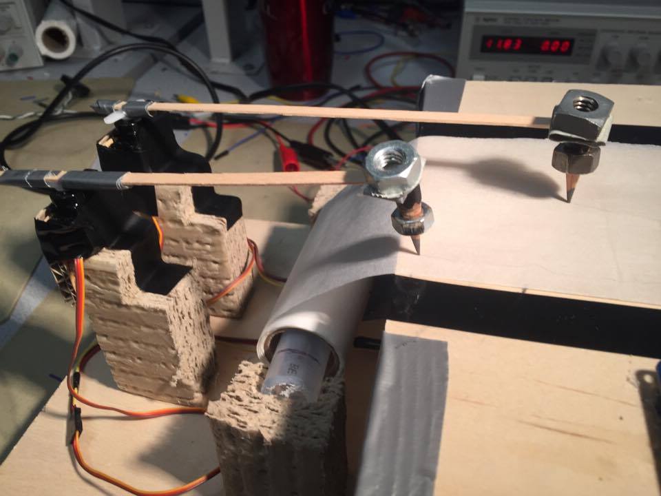
Servo Writing Mechanism
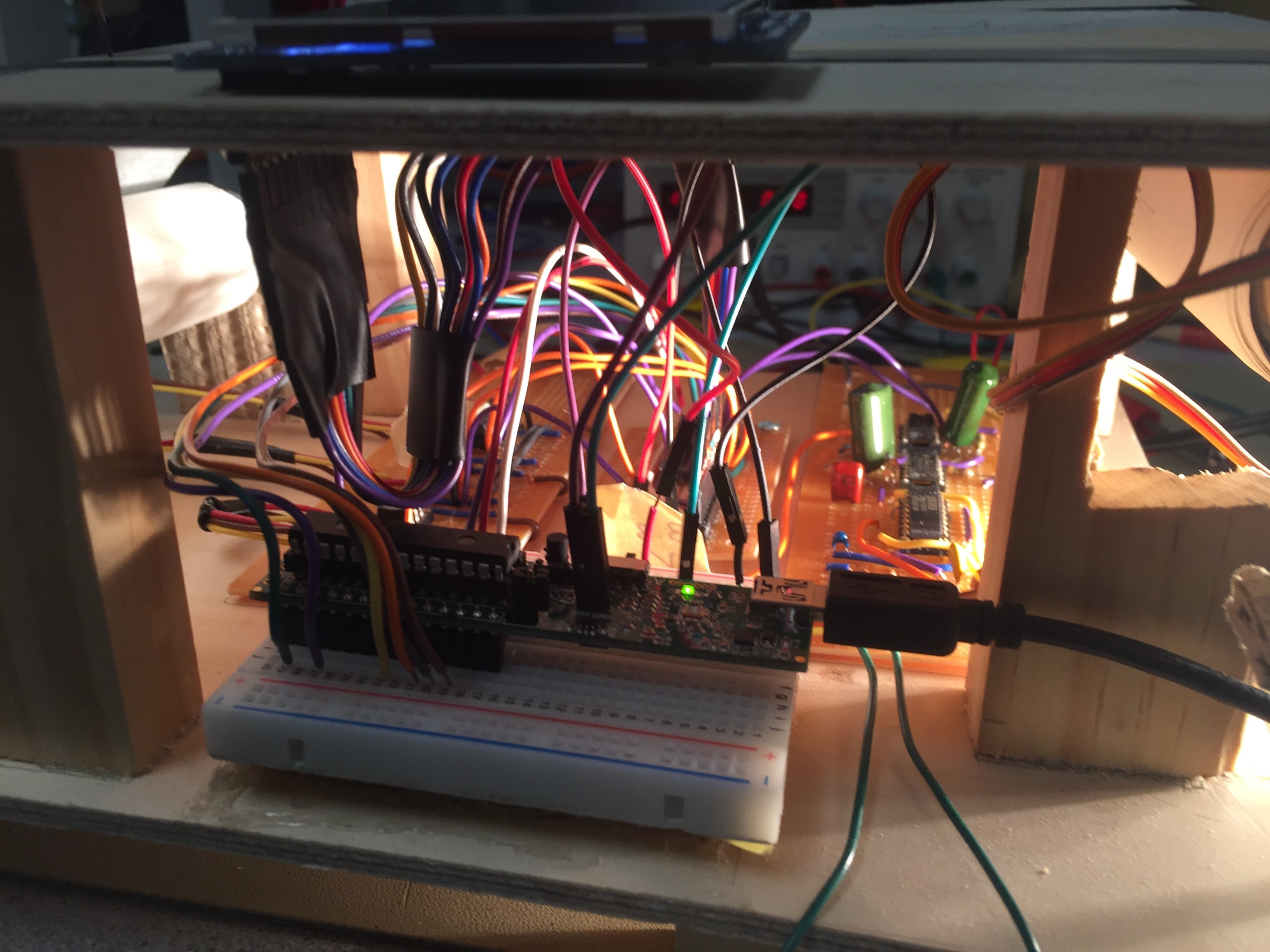
Circuits Underneath Writing Platform
As one can see, we have all of the circuits placed under the raised platform. The TFT is on the top platform. The two servos controlling the drawing needles are on one side of the platform with the roll of paper. The paper is rolled out over the platform and connected to a tube that is rotated by another servo on the other side of the platform. As the servo on the right side rotated, it pulled the paper along while the needles moved side to side. These synchronized movements created two waveforms on the paper that closely resembled what was shown on the TFT
Software Design top
static PT_THREAD (protothread_lcd(struct pt *pt))
Electrocardiogram
For the electrocardiogram the output of the circuit was connected to an analog pin on the PIC32. We used pin 24, AN11 on the PIC. In order to read in the data from the analog pin we setup the analog to digital converter on the PIC to read from pin 24 by using SetChanADC10. Then we acquired the data from the ADC and set a variable v equal to the data being read in from the ADC. Next v was scaled to a form that could be used to plot the waveform on the TFT. In order to plot the data as a waveform, we had an if statement that incremented the x value of each data point being plotted until the x value reached the limit which was 320. When x reached 320, the TFT cleared and x was reset to 0 so the waveform could be drawn across the screen again. The y value of each data point was equivalent to v. This thread had a yield time built in that was 50ms which meant that the data was being sampled at a frequency of 20 Hz. This was sufficient to recreate the expected waveform output from the ECG.
Stretch Sensor
The code for plotting the stretch sensor data was identical to the code for the ECG other than the pin from which the ADC was sampling. As described above, first we set the channel for the ADC, but this time we set it to pin 26, AN9. Then we read the data from the ADC and scaled it to an appropriate form that could be used to plot the waveform on the TFT. Once again we had an if statement that plotted the data points on the TFT by incrementing the x value until it reached 320 and the scaled data from the ADC was the y value. The sampling rate was also once per 50ms.
static PT_THREAD (protothread_angle(struct pt *pt))
In this thread we wrote the code that controlled the angle to which the servos moved based on the data that came into the PIC from stretch sensor circuit and the ECG. The servos are designed to move by pulse width modulation (PWM). For a typical servo, the pulse repeats every 20 milliseconds and the width of the pulse determines the angular position of the servo rotor. The pulse width ranges from about 1 to 2.5 milliseconds. To create the pulses we used Timer2 with a prescaler value of 32 and a period of 25,000. This created a pulse that repeated every 20 milliseconds. The period value was calculated knowing that the system runs on a 40 mHz clock using the equation .02=x32/(40,000,000).
Then we set up the Output Compares. Each servo used its own output compare, OC2, OC3, and OC1. OC2 was used for the servo writing ECG data, OC3 for the servo writing stretch sensor data, and OC1 controlled the servo that pulled the paper. Each output compare was setup to initially have a compare value of 1250, which corresponded to approximately 1 millisecond for the PWM.
In this thread we continuously updated the position of the servo by calling the function SetPulseOC*, where the * is an integer indicating which output compare unit is being used. The position was calculated based on the sensor data received. The positions can be approximated by the table shown below.

PWM Table
In order to calculate the precise angular position needed to recreate the ECG and stretch sensor waveforms, we first determined the range of y values for each waveform. The ECG stayed within the bounds of 75 to 235 and the stretch sensor data was within the range 50 to 100. In order for the servos to rotate fast enough to keep up with the data, the max angle we used was 30 degrees instead of 180. When we tested with a max rotation of 180 degrees the servo was not able to rotate back and forth in time to keep up with the incoming data. One way to fix this was by increasing the yield time for the thread that controlled the servos, but then this would change the sampling rate for the servo thread and the waveform would not resemble the one on the TFT. We chose to shorten the angle and keep the sampling times the same as this also solved the timing problem with the servo rotation. Thus, for the ECG servo a y value of 75 mapped to an angle of 0 degrees, (OC value of approximately 900), and a y value of 235 mapped to an angle of 30 degrees (OC value of around 1100). Using this information we wrote a function that took the y value from the ECG circuit as its input and outputted an OC value that was used in SetPulseOC* to tell the servo what angle to rotate to. A similar approach was used in writing the function for the stretch sensor servo. The servo that pulled the paper was set to a constant OC value so that the paper was consistently pulled at one speed.
int main(void)
In this thread we set up system wide interrupts, initialized the TFT display, initialized the threads, set up the ADC, configured the timer, setup the output compares, and scheduled the threads.
Results top
One safety concern we had when building the circuit was making sure that there was no way that the user could get electrocuted when we connected the electrodes to his or her body and powered the circuit. We used a 12V power supply to power our circuit. Since we were not connected to the power supply chassis ground it was safe to use. Additionally we performed all testing of the ECG using a function generator before placing electrodes on ourselves.
In the image below we have the TFT display which shows the heartbeat in red and breathing rate in green; additionally we show the two waveforms translated onto paper by the servo.
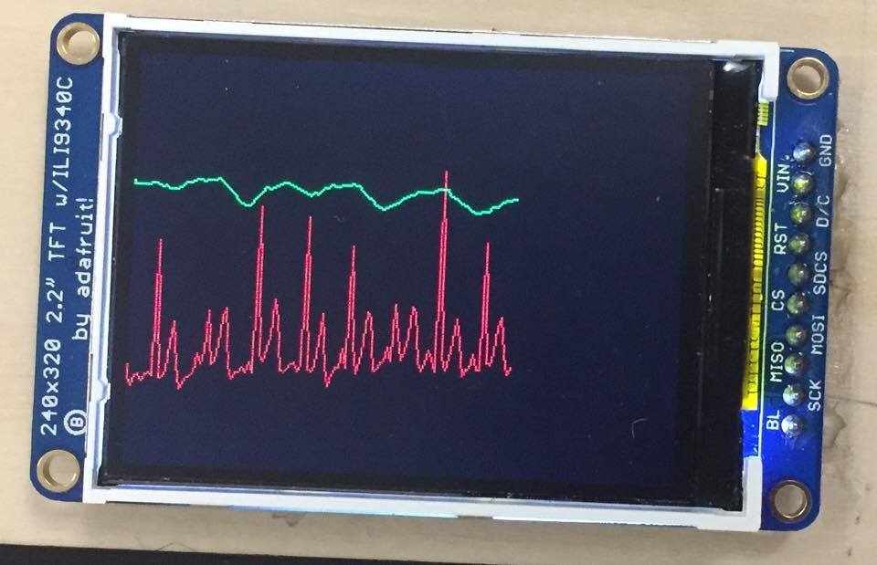
TFT Display
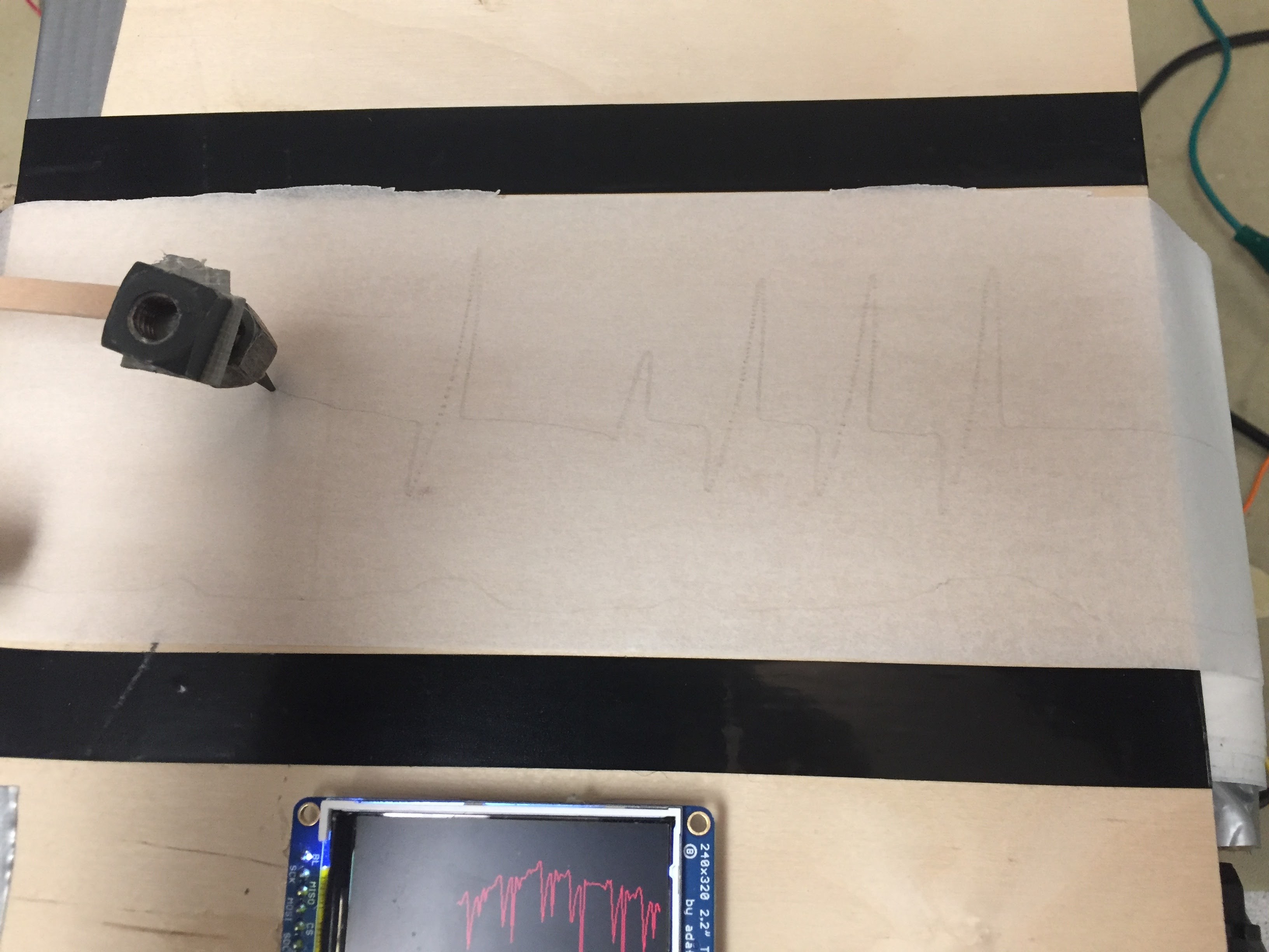
Waveform on Paper
Once the whole system is connected, the servos may occasionally have a slight jitter at the beginning, but everything else will start processing automatically. Our polygraph machine is usable by anyone as long as we are able to place the electrodes in such a way to detect heartbeat.
As seen above in the two videos, the servos and TFT display show the heartbeat and breathing rate in real time.
Conclusions top
Future Work
Our initial design for the polygraph machine was modified heavily throughout the semester. We had expected to create three sensors, including a prespiration sensor, which we did not get to this semester. We also had hoped to get a much more readable printed waveform from the machine, but we had a lot of difficulty finding a writing mechanism that would be light enough to be supported from the servos and would write easily without pressure. If we were to continue to modify the project, next time we would try to add more sensors to the polygraph, find a better printing mechanism than graphite (possibly different colors as well), and some general touch ups to the whole system. A last minute mistake with the placement of the PIC32, forced us to move the PIC32 to a completely separate breadboard with wires making the connection from the PIC32 to its original perf board; it would be nice to be able to put the PIC32 back in its intended place and remove all the loose wire connections. The TFT was also connected via loose wires and were a hassle to connect; it would be nice to make a header pin to make connecting the TFT simple.
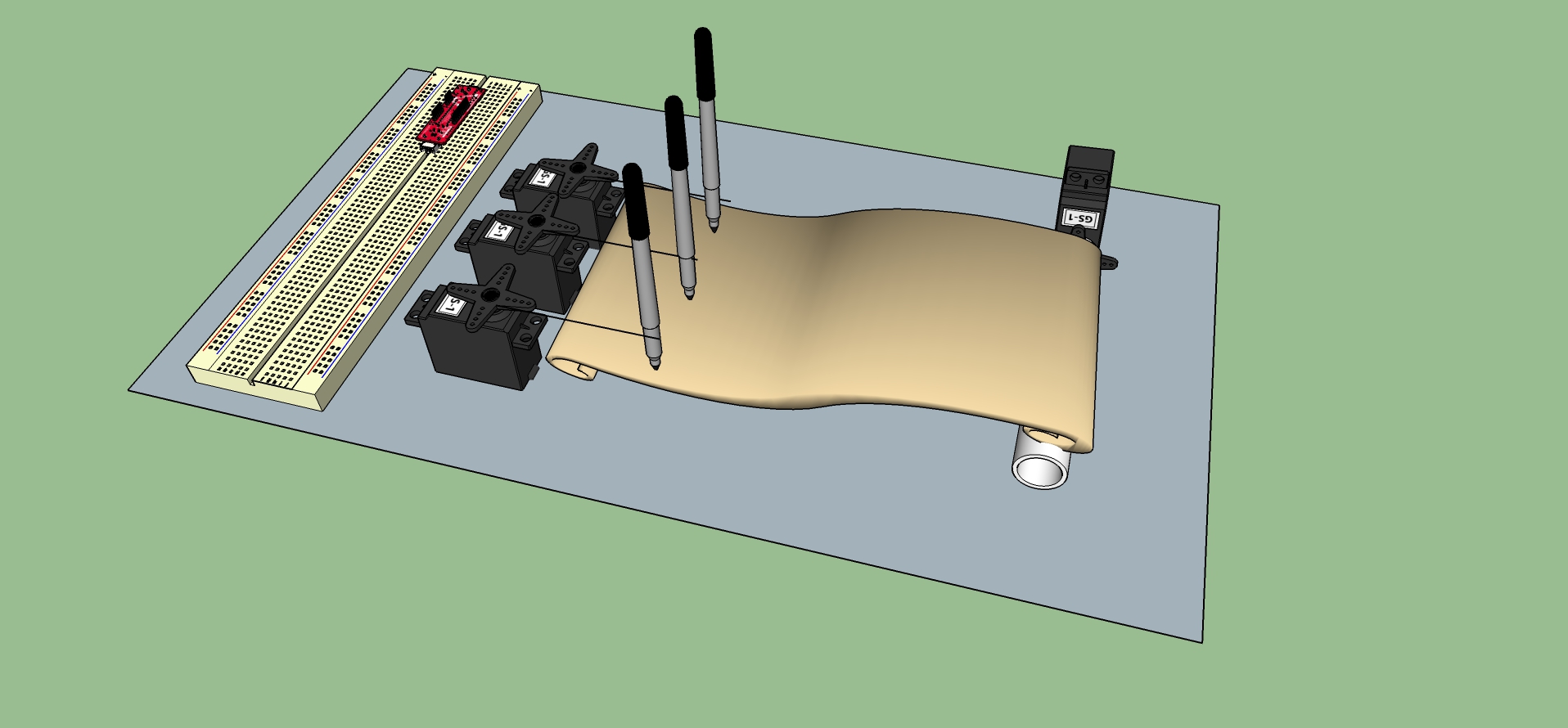
Original Mechanical Design
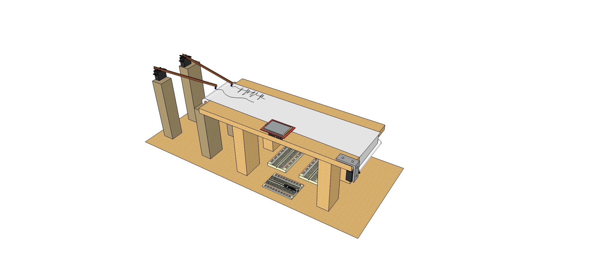
Final Design
Additionally a lot of the system was held together by duct tape/electrical tape, it would be nice to replace some of these spots with hinges or something more permanent to make the system more secure and aesthetically pleasing. Other than that the project did meet our expectations. We hoped to create sensor circuits capable of detecting various human body reactions and translate those reactions into a printable waveform.
Intellectual Property Considerations
We did not reuse anyone else’s code or design. We did reference a ECG circuit design from Sean Hubber and Crystal Lu as stated in our References.
Ethical Considerations
With respect to the IEEE Code of Ethics, we took many precautions for the responsibility of a person’s health and safety when using the polygraph machine. The machine is powered by a 5V and 12V line, so it’s very important to us that whoever uses the machine won’t get electrocuted. While creating the ECG sensor, we did all testing using a function generator that would simulate the pulses of a heartbeat so we didn’t risk hurting anyone. We also made sure that the sensor was not connected to the power supply chassis ground terminal and it was designed with sufficient DC isolation to prevent electrocution. Since the machine prints a person’s heartbeat and breathing rate, we only let a person use the machine with full understanding that their information will be calculated and shown on the machine. Additionally we will not publish any of this information anywhere without their permission. We also took careful consideration of the placement of electrodes and stretch sensor as to not make the user too exposed or uncomfortable with the placement. The stretch sensor can be placed around the user’s waist (around their clothing) and the electrodes can be placed at the user’s wrists. The electrodes can be placed in other locations such as the neck and chest as well.
Appendices top
Appendix I.
The group approves this report for inclusion on the course website.
Appendix II. Program/Code
For other included files, like config.h, tft_master.h, pt_cornell_1_2.h, you can find them on the ECE4760 web page.
- main.c (15 KB)
Appendix III. Schematics
PIC32 Schematic
ECG Schematic
Stretch Sensor Schematic
Servo Schematic
Appendix IV. Cost Considerations
| Component | Quantity | Cost/Component | Total Cost | Source |
| Microstick | 1 | $10.00 | $10.00 | Lab rental |
| Solder board | 2 | $2.50 | $5.00 | Lab rental |
| Solder board (2 inch) | 1 | $1.00 | $1.00 | Lab rental |
| Power Supply | 2 | $5.00 | $10.00 | Lab rental |
| PIC32 | 1 | $5.00 | $5.00 | Lab rental |
| TFT | 1 | $10.00 | $10.00 | Lab rental |
| Modified Servo | 1 | $15.90 | $15.90 | Amazon |
| Mini Servo | 2 | $2.99 | $5.98 | Digikey |
| Roll of Paper | 1 | $6.00 | $6.00 | Cornell Store |
| Graphite | 2 | $0 | $0 | Donated |
| Paper Tubes | 1 | $0 | $0 | Trash |
| Stretch Sensor | 1 | $0 | $0 | Lab |
| Electrodes | 2 | $0 | $0 | Lab |
| Electrode Gel | 1 | $0 | $0 | Lab |
| Wood | 1 | $0 | $0 | Lab |
| Bread Board | 1 | $6.00 | $6.00 | Lab |
| Jumper Cables | 1 | $0.10 | $0 | Lab |
| Sip or Header Socket/Plug | 46 | $0.05 | $0.70 | Lab |
| Alligator Clips | 9 | $0.88 | $7.92 | Lab |
| Final Project Cost | $85.80 | |||
Cost Considerations
Appendix IV. Team Member Tasks
Joyce - Servo circuit design, implementation and integration of code, debugging/testing system, design of writing mechanism, final write up, website
Daria - ECG and stretch sensor circuit design, implementation and code, integration of sensor circuits with servos, building physical structure,final write up
References top
DataSheets
- TFT Data Sheet: https://www.adafruit.com/datasheets/ILI9340.pdf
- PIC32 Data Sheet: http://people.ece.cornell.edu/land/courses/ece4760/PIC32/Microchip_stuff/2xx_datasheet.pdf
- Mini Servo Data Sheet: https://media.digikey.com/pdf/Data%20Sheets/Seeed%20Technology/108090000_Web.pdf
Vendors
- http://www.banggood.com/Wholesale-Emax-ES08A-Analog-Micro-Servo--p-68706.html
- https://www.amazon.com/BotBrain-Continuous-Rotation-Robotics-Servo/dp/B00FGDG3WK
Example Code/Circuits
Acknowledgements top
Thank you to Sean Hubber and Crystal Lu for providing their ECG circuit schematic as reference.
Also special thanks to Professor Joe Skovira for assisting us with the mechanical design of the polygraph and providing us with materials to make the drawing needles. We really appreciated all the help you provided us with.
Additionally we would like to thank Bruce Land for mentoring us throughout the course of this project and the whole semester.