Air Bass
- Caitlin Stanton (cs968)
- Peter Cook (pac256)
- Jackson Kopitz (jsk363)
Introduction
High-Level Overview
Social Impact
Our plan for this project was mainly for entertainment purposes, and is not dangerous. Nevertheless, we constructed a user-friendly playable instrument that is similar to a bass guitar. As far as we know, this is a novel idea that we originated. We were able to achieve this goal by combining information discussed in previous labs with our own ideas.
In theory, our design is relatively inclusive for all types of ability. This device is one that can be held like a guitar, but can also be placed on a table or the floor to be played, meaning that users who can’t hold objects for a long time and/or in an upright position can also play. The use of a glove fitted with flex sensors makes playing our air bass easier than a real guitar since the user does not need to make full contact with the strings and their fingertips in order to produce a sound. Users still need to have two functioning hands so that they can strum using the flex sensor glove with one and simulate fret positioning with the other, but this is theoretically be easier than literal plucking and holding down strings.
Color and identifying specific shapes/patterns don’t play much of a role in our implementation, so those who have color blindness or poor eyesight should have a similar experience as those with full seeing ability. For full user experience, some hearing ability is needed—this doesn’t help with interfacing with the device itself, but improves the general functionality of our project as a way to practice guitar without physically owning one. Being able to hear the synthesized notes enhances the user’s chances to self-correct the placement of their fingers and the timing of their strumming so as to play songs that they choose.
Our project doesn’t involve any over-air communication, so there are no specific IEEE or FCC standards that we must follow. Additionally, our use of inputs and outputs that pose little to no harm to the user imply that there aren’t any major ANSI, ISO, or FDA standards that are applicable. Copyright claims are not much of a concern to our team, as the user will be responsible for any melodies they create and how they wish to share them.
Implementation Overview
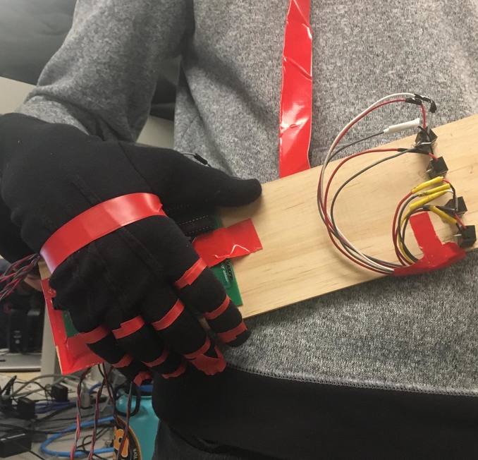
The slab of wood is used to mimic the neck of a bass guitar, as shown in Figure 1 below. To synthesize the four individual strings, we aligned four beam break sensors parallel to the length of the wood. If a finger is placed on one of the “strings”, the line break sensor registers this and it narrows down the range of potential frequencies of sound that we’d have to output. Ultimately, nothing is played until one of the strings are strummed by flexing a finger in the glove - then, a frequency is output to the DAC with an envelope that starts and stops depending on the reading from the flex sensor.
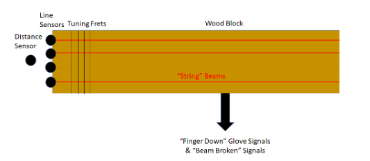
Figure 1: Diagram of sensor placement on the neck of the AirBass
Line break sensors can only detect if an object has passed between the pair, not the location of where the object broke the line. Since the positioning of your fingers on each string of a guitar is crucial to playing a certain note, we need to analyze what finger is being placed on the “string” and at what fret.
For the latter, to determine at which fret the user is playing, we used an ultrasonic distance sensor. This sensor is placed at the end of the wood slab to measure how far down the next of the guitar the user’s hand is. This distance data is used to decide which fret the user is playing, based on the length of the neck of a guitar and the typical placement of each fret. This data is used in part to determine which frequency the user is attempting to play. Note that in our implementation, for simplicity we assume that the user is playing a single note at a time since we did not want to overcomplicate our logic.
For strumming, we use a black polyester glove with short flex sensors attached to the inside of each finger, as shown in Figure 2. These sensors have a resistance of ~30KΩ when at rest and up to ~100KΩ when flexed. When the user bends a finger, we determine which finger is bent, which line break sensor has been broken, and how far down the neck the user’s hand is to determine which note is being played. This also serves as a kind of redundancy check, so that a note is played both when the string/line is broken and when a corresponding finger is bent.
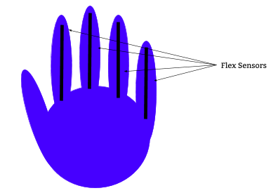
Figure 2: Diagram of flex sensor glove
Using additive synthesis, we produce approximately bass-like sounds, similar to lab 1. We use the DAC, setting the output in an ISR that is timed to accurately sample desired notes, the audio jack, and the lab speakers to play the music the user requires.
In-Depth Breakdown
Break Beam Sensors
Our AirBass had four pairs of break beam sensors. These sensors are the four strings on our guitar. Each pair of break beam sensors has both an emitter and a receiver. The emitter sends an IR signal to the receiver and the receiver sends a signal to the MCU whether it has received the signal or not from the emitter. When the emitter and receiver are in line, the receiver sends a low signal to the MCU. If they pair is not inline or if something is blocking the signal, then the receiver sends a high signal to the MCU. Our circuit is shown below in Appendix C. We use a 10kΩ pull up resistor and a 1kΩ series resistor to protect the MCU to process the output signal of the receiver. Both the emitters and the receivers were powered by 3.3 V from the board.
We quickly realized that if all receivers were on one end of the guitar with all emitters on the other end, there would be interference across the pairs such that when we blocked any given receiver and emitter pair, the receiver would still output receiving a signal because of the signals from the other emitters. Each emitter and each receiver has a cone out of about 10 degrees. To try and overcome this issue, we alternated the emitters and receivers on each side of the guitar neck. This allowed there to be more distance between the emitters on each side so that the receiver would not be in the cone of an emitter that was not its designated pair. This also did not work and there was still interference. The final idea we had was to angle all of the beam break sensors to capitalize on the cone of their signal transmission and reception. We angled the E and A strings’ beam break sensors and the G and D strings’ beam break sensors about 10 degrees away from each other so the edge of each of the emitter’s cone is in the edge of the detection range of its receiver’s cone. Figure 3 shows a diagram of the beam break layout with directional arrows indicating the IR beam and the cone, illustrating how the sensors do not interfere with one another.
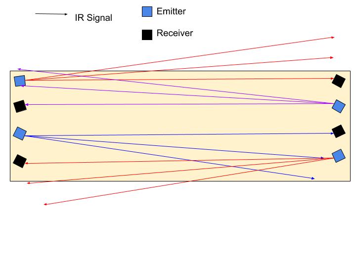
Figure 3: Block diagram showing the alignment of emitter and receiver pairs, so as to reduce interference
We have a thread called protothread_beam to keep track which
of the beam break pairs are broken, and thus which one of the strings are
being pressed. This thread runs every 5 milliseconds, since no human finger
can move or shift faster than a few dozen Hz, let alone 200Hz. In this thread,
we first read from the port Y expander. To do this we enter an SPI critical
section, load the value of the port Y expander into porty_val,
and then exit the critical section. Next we have four checks. Each of the
checks is to determine if the beam is broken based on the bit sets within
porty_val. For the E string for example, we check if
(porty_val & BIT_7) != 0x80). Since the E string receiver
sends the signal to pin RY7, we check if the 7th bit from the port expander
is low. If the bit is low, then we assign e_string to 0, meaning
that the beam is broken. If the signal was high, then we would assign
e_string to -1, indicating that the E string is not pressed.
We do this check for each of the four strings and assign e_string,
a_string, d_string,and g_string
to the appropriate values. Later in our code, we used the information if
the string is pressed to determine whether we should calculate at which
fret the user’s hand is placed. This is important because if the string
is not broken, then we do not need to calculate where the hand it since
an open string is being played.
Ultrasonic Distance Sensor
On a guitar, the sound of the note being played changes not only based on the strings being plucked but also the fingers placed on the frets.
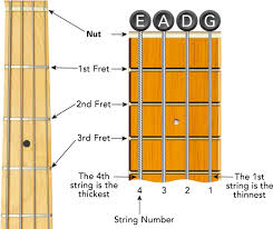
Figure 4: Typical fretboard of a bass guitar, with strings and fret annotated
To determine which of the frets were being placed, we used a SparkFun SEN-15569 ultrasonic distance sensor. The general overview of this sensor is that, once triggered, eight 40kHz signals are sent out to potentially reflect off of any objects that are in front of the sensor. If a signal is reflected back, then the outputted signal (aka echo) is equal to the difference in time between the pulse and the received pulse. For this to be incorporated into our prototype, we wanted to use the ultrasonic distance sensor to detect the distance from the top of the neck of our bass guitar to the user’s playing hand. This result would then be used to determine on which fret the first finger was placed. This sensor needed a 5V power supply, which we were able to provide using the MCU Vin pin. There was no need for a voltage regulator because we knew our final prototype would use the 5V power adaptor. In the case of the PIC32 being powered with a separate battery, a voltage regulator would be needed to keep the sensor powered at a steady 5V with no sharp increases in voltage or spikes in current.
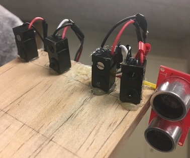
Figure 5: Ultrasonic distance sensor placed alongside beam break sensors on final prototype
The implementation of this general process can be seen in the thread
protothreads_distance. The trigger—which, when set,
would start the series of pulses to read the distance to an object—was
connected to MCU pin RPA1, which had been enabled as an output. As
long as the define use_uart_serial statement was commented
out in the config_1_3_2.h file, there was no other use
for this pin, and therefore nothing preventing us from sending the
trigger signal on it. Pin A1 was set high for one millisecond and
then cleared. The minimum length of time that A1 needed to be set for
was 10 microseconds, so the one millisecond delay was reasonable.
The actual reading from the echo signal was done using an input capture on MCU pin RB13. An input capture is a hardware timer, where the time of specified edge of a signal received by the input capture pin is measured. This provides an extremely accurate timing of events, up to within a cycle of the signal edge occuring. We decided to use this hardware timer, rather than reading the signal on a digital GPIO pin and using a counter variable, because it wasn’t as likely to hang. If we had used the GPIO pin and software timing route, our logic for the protothread would’ve kept it stuck waiting for a pulse back, thereby preventing us from setting a new trigger signal.
The code written to initialize the input capture can be found between
lines 521 and 533 in main(). The input capture required a
timer, as it would be used to keep track of the edge of the inputted
signal. For our program, we used timer3 for this purpose, and initialized
it to take continuous readings and have a prescaler value of 32. The
prescaler prevented the results from the input capture to not overflow.
An additional precaution for this was declaring the distance readings as
unsigned integers.
Next we configured capture1 to be connected to an interrupt service
routine (ISR) that would read integer timer values on timer3 due to the
falling edge of a signal. Using an ISR prevented any other parts of the
program from overriding the distance sensor so that we would get the most
accurate readings from the input capture. Taking values from the falling
edge of the signal would only provide a distance once the entirety of a
returned pulse had been received. Lastly, MCU pin RPB13 was connected to
capture1 using PPS.
Since the ISR would preempt any other functions that were running at
the time, we took care to make the ISR as brief as possible to not let
any other functions hang. This meant that the ISR only ran two lines of
code: mIC1ReadCapture() to save the value off of timer3
when the reflected pulse was received; and mIC1ClearIntFlag()
to clear the timer interrupt flag.
Within protothreads_distance, after the trigger signal
was set for one millisecond, the interrupt flag for the capture1
ISR was cleared and timer3 was set to zero. The first function
was performed so that capture1 would be accurately updated
with the most recent falling edge. The second call was made so that no
additional arithmetic had to be performed to find the length of time
between the 40kHz pulses and the reflected pulse.
Once the ISR read from the input capture pin, an finite impulse response filter was applied to make the value more reliably accurate, otherwise we noticed a large amount of fluctuation. The averaging was done over the four most recent input capture values, which were saved into a circular buffer whose starting and ending indexes were constantly updated. The variable distance would be incremented by the difference between the most recent reading and the least recent reading in this circular buffer.
When reading the echo pin from the sensor on the oscilloscope, we noted slight noise. The theory behind this is that it’s caused by the switching within the sensor itself, most likely due to the MHz clock. At first, we placed an electrolytic capacitor between power and ground. Although it did reduce noise, it has an internal frequency of around 100kHz, leading to slow switching rates. Ultimately, we built a low pass voltage divider filter, as shown below. We made sure to use a ceramic capacitor as it has a faster internal frequency, and therefore our circuit would have a faster response.
Figure 6: Our protoboarded echo pin circuit
Now that the distance reading was averaged, it had to be calibrated. After working with the distance sensor a bit, we noticed that the distance values changed based on the positioning of the object it was looking at. In the case of our prototype, this object was the side of a hand, which is extremely hard to maintain in a static position with the same amount of surface area being presented, despite the strings and/or frets it’s at. To remedy this, we spent a decent amount of time measuring the distance sensor’s output across various combinations of depressed strings and frets. The calibration data for this can be seen in the table in Results.
Flex Sensors
In order to accurately determine when individual strings of our bass are “plucked,” we used the SparkFun SEN-10264 two-inch flex sensors. At a high level, the idea for implementing these sensors is that we could use the variable resistance across the terminals in a voltage divider circuit, so that the output voltage could be used to determine which of four strings is being plucked (one string corresponding to each flex sensor). The result is that we can accurately pluck open strings, start and stop playing individual notes independent of the fret/finger position decided by the beam breaks and distance sensor, as would be the case in a real bass. To further liken the experience of our AirBass to an actual bass guitar, we have the flex sensors attached to the inner palm of a glove so that the integrated system can register moving a finger while wearing the glove, and begin playing the desired note. The final setup is shown below.
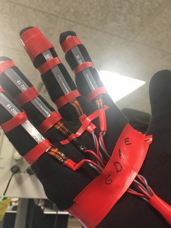
Figure 7: Final setup for flex sensor glove - pinky, ring, middle, and pointer finger control plucking of the G, D, A, E strings, respectively
To construct our voltage divider (to divide the supply Vcc = 3.3V when flexing the device), we first measured the resistance of the flex sensors. We found that they have an unflexed resistance of about 30K, which approximately linearly increases to about 100K when fully flexed. Noting these values, we decided to put the flex sensor in parallel to the output and chose a series resistance Re = 50K to Vcc, since this gives an output voltage that ranges between ~1.2V and ~2.2V, which is appropriate for 3.3V level logic.
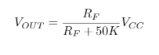
Figure 8: Equation for the voltage divider used for reading a varying output voltage from our flex sensor
Next, we noticed that for our final implementation we only cared about a true/false value answering the question “is string i being plucked?” for each of the four strings i. Accordingly, we tried a few circuits to convert this analog output voltage (ranging ~1.2V to ~2.2V) to a digital high or low signal. Initially, we attempted to use the voltage divider output for triggering an open drain FET (i.e. with the source grounded and the gate this voltage divider output), since then we could easily pull the output voltage up to the MCU’s power rail. We abandoned this approach for two reasons: (1) the FET took relatively long to trigger and we saw an approximately exponential rise time on the oscilloscope, which is no-nideal here since we need a fast response to play the bass realistically, and (2) to avoid any mechanical effects of the sensor and make it “easier” to pluck the strings, we decided we needed some hysteresis in our trigger circuit so that a user would have to intentionally unflex a finger to stop plucking the string rather than this kind of event happening accidentally. Hence, we used a Schmitt trigger.
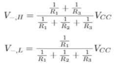
Figure 9: Equation for the Schmitt trigger, specifically with resistance values R1 = 12K, R2 = 15K, R3 = 30K, RE = 50K
As shown in Figure 8 and in the circuit schematic in Appendix C, the output of our voltage divider is the input voltage for an inverting Schmitt trigger, on the inverting terminal of the amplifier. The resulting circuit, with resistance values as stated above, has a high threshold of 2.1V and a low threshold of 1.5V. That is, when the output is currently low (sitting at 0V) and the input (V-) to the inverting terminal goes above 1.5V, the circuit triggers and brings the output to 3.3V. When the output is currently high and the input goes below 2.1V, the circuit triggers and brings the output to 0V. Since our voltage divider ranges over values ~1.2V to ~2.2V, these thresholds are within our capabilities and we effectively have an integrated circuit whose output will be digital high when the sensor is flexed and low when it is not flexed (with some hysteresis). For our final design, we have four of this circuit (one for each string/flex sensor) and in practice, we saw that while this did work reasonably well, for some of the sensors unflexing to go back below the high threshold was a little difficult. Not all of the sensors have the same range of resistances, and for one sensor in particular it was difficult to make the digital high output go low again, while it worked like a charm for the others.
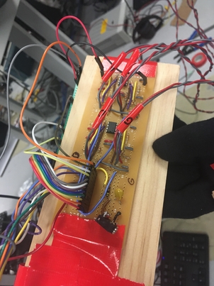
Figure 10: Completed circuit used in demo, with four duplicated Schmitt triggers near the top of the image
Final Integration
All of the aforementioned sensors had their inputs and outputs combined to produce a series of synthetic bass notes based on the user. Each thread for the sensor set variables that were used to properly determine the frequency of this sound, as well as when it occurred and for how long.
Within main(),timer2 was configured to interrupt
909 times a second (equal to 40MHz divided by our hardcoded sampling frequency,
44kHz). To make sure the big board would be outputting to the DAC pins, the
chip select was also set by making MCU pin RB4 an output. Then sine lookup
table was calculated. To do this, we first created a table of regular sine
values sine_table, to cover a complete cycle of a sine wave
with sine_table_size datapoints, and then created a new table
sine_table_harmonix also covering a complete cycle, adding
five harmonics with hardcoded weights to the original wave to produce a
more string-like sound. We found these weights on the DAC page of the
ECE 4760 website. Each value of sine_table_harmonix was then scaled to
be within the inclusive range of [-1,1], much like the original sine table
created earlier in the function. Lastly, the phase increment array
ph_incr was filled with frequency values that matched the
specific string/fret combinations of a bass guitar—this array contained
23 values, as each string had an open frequency and six frets, and each
string was separated by fifth (such that playing the fifth fret on a
string would produce a sound equivalent to the next open string).
The DAC ISR, connected to timer2, was the final piece of
the puzzle. First it cleared the timer2 interrupt flag.
Once that was done, conditional logic was used to determine the frequency,
from ph_incr and sine_table_harmonix, that would
be output to the DAC. First, it had to be seen if at least of the strings
had been “plucked”, as determined by the flex sensor glove.
The flex sensor outputs were read using MCU pins Z4,Z5,Z6,Z7 on the port
expander. In an SPI critical section we read the current Z port into a local
variable and outside this critical section checked individual bits of the
word to determine which flex sensors were flexed and which were not. We
set integers e_pluck, a_pluck, d_pluck,
g_pluck to 0 or -1 depending on which bits of the word were
high to indicate whether or not a sensor was being flexed.
If a string had been plucked, the phase variable for that specific string
(e_phase, a_phase, d_phase, g_phase)
was incremented. The value to increment each phase variable by was at
index 5i*i_fret within ph_incr, where the i in 5i corresponds
to each string represented as an integer (E = 0; A = 1; D = 2; and G = 3)
and the i in i_fret corresponds to each string (E, A, D, G). The reason
for the former definition of i is to nail down the fact that the strings
are separated by fourths within ph_incr, and therefore the
next open string frequency can be found at every fifth element of the table. The
latter definition stems from the readings from the ultrasonic distance sensor.
The distance ranges from the ultrasonic distance sensor were used in a
series of conditional statements to set the fret for each individual string
being depressed: e_fret, a_fret, d_fret,
and g_fret. If none of the four strings were depressed (meaning
that zero of them had their beam break broken), then all four fret variables
were set to zero, indicating an open string. If at least one of the four
strings were being depressed, then the fret variables were set if 1) that
specific string was depressed and 2) the distance sensor reading was within
the range for that fret. Since the farther frets would have larger distance
readings, those ranges were used in earlier if statements. The reasoning
behind this was that it was that a higher distance range was easier to a
chieve, and so by putting these ranges earlier, it ensured that lower
distance readings wouldn’t accidentally be set to the wrong fret. For
example, on the E string, the first fret was expecting a distance reading
of less than 120—if the logic for setting the first fret came before the
logic for setting the second fret, then the second fret would be the final
(yet wrong) result.
Cascading ranges (which checked to see if distance was less than the calibration value) were used rather than constricted ranges (which checked to see if distance was both greater than a calibration value and less than another calibration value). This was because of the variation between the boundaries of each fret. We felt that using cascading ranges would cut down on the amount of accidental fret switching due to the ultrasonic distance sensor not being as precise as possible.
The variable sum_strings was used to store the sine values
from sine_table_harmonix. Similar to the logic to find the
phase variable for each string, if a string had been plucked, sum_strings
was set to the value in sine_table_harmonix indexed at the
string’s phase variable (which had been shifted by 24 to prevent the
index from going out of bounds of the table).
Now that the frequency of the sound had been set, it was time to set the
amplitude envelope of the sound wave itself. This was also based on the
flex sensor glove output. Boolean state variables string_depressed and
prev_string_depressed indicated whether or not one of the four
strings is currently being plucked or was being plucked in the previous
read to the Z port. If we transitioned from nothing plucked to some string
being plucked, we started timing a new note/amplitude envelope by setting
current_amplitude to 0 and curr_attack_time to
0 as well. Similarly, if we transition from something plucked to nothing
being plucked, we set current_amplitude to max_amplitude
and curr_decay_time to 0.
In the audio ISR, even more conditional logic is used around string_depressed
and prev_string_depressed. If at least one string was
depressed and curr_attack_time had not reached its maximum,
this meant that the sine wave hadn’t reached its maximum amplitude, and
therefore curr_attack_time and current_amplitude
were increased accordingly. Otherwise, if the curr_attack_time
was at maximum value, the current_amplitude was set to
max_amplitude for redundancy. If no strings were depressed and
curr_decay_time had not reached its maximum, this meant that
the sine wave hadn’t reached its minimum amplitude, and therefore
curr_decay_time was incremented and current_amplitude
decremented. Otherwise, if the curr_decay_time was at maximum
value, current_amplitude was set to 0 (the minimum sine wave
amplitude) for redundancy. The attack portion of the sine wave increased
linearly, while the decay part of the sine wave decreased linearly. The
result of this logic gives the ability to play sustained notes with the
attack and decay part of the envelope so that it sounds less harsh and
ideally more like an actual bass.
The final result of AirBass was sent to MCU pin DAC_A, which was the sum of
2048 and the product of current_amplitude and sum_strings.
Since sine_table_harmonix is between the range of -1 and 1, so
is sum_strings. Multiplying this variable by current_amplitude
moves it to the range -208 to 2048. Adding 2048 further modifies this range
to 0 to 4096 so that the DAC can properly receive the sine wave.
This was then written to SPI to actual produce the sound, after which
the SPI was free to be used by either the port expander or the DAC.
To prevent any unwanted collisions on the combined use of SPI from the DAC
and the port expander, we made sure to use SPI critical sections wherever
needed and to limit the amount of code within them, so as to not take too
much time.
An audio jack was soldered from the output of DAC_A to be plugged into a speaker so the user could hear the produced sound. There was minimal crackling, so we added a low pass filter between DAC_A and the audio jack to keep the sound as smooth and steady as played by the user.
Results
Figure 11: Our final demo!
As shown in our final demo video, we were able to put together a functioning prototype for AirBass. It implemented the break beam, ultrasonic distance, and flex sensors we set out to use at the start of this six-week endeavor. Despite the output of each being fairly simple, it took a lot of work to fully understand each of the sensors, as well as what (if any) accompanying circuits were necessary.
The final result experienced no lag when producing a sound, whether it was an open string (a plucked string with no finger placement breaking a beam sensor) or a fingered note. The produced sounds matched the expected frequency and amplitude, no matter the string/fret combination, when checked on the oscilloscope.
One of the shortcomings we experienced was due to the calibration of the distance sensor. If the user’s hand was tilted differently than how it was when calibrating—reducing or increasing the amount and angle of the surface area of the side of their hand—the distance measured would change slightly. This slight change, depending on the distance of the fret, would greatly affect which fret the program would detect as being played. For example, as shown in the table below, the second fret of the A string was at a distance value less than 140. If the user’s finger was placed on the second fret but their hand was tilted more towards the distance sensor than previously, the distance sensor would see a pulse reflected back quicker, therefore reading a smaller distance than expected. This could drop the distance down below 120, playing on the first fret. If the user’s hand was tilted away from the distance sensor, the third fret could be played instead.
| Fret Number | E | A | D | G |
|---|---|---|---|---|
| 1 | 120 | 120 | 150 | 180 |
| 2 | 140 | 140 | 180 | 200 |
| 3 | 180 | 170 | 220 | 240 |
| 4 | 230 | 200 | 250 | 260 |
| 5 | 260 | 240 | 290 | 320 |
| 6 | 320 | 270 | 320 | 350 |
Figure 12: Table of the final calibrated values for the ultrasonic distance sensor, based on strings and frets
This issue was reduced when the calibration was specified based on the string, after we recognized that the positioning of the user’s hand would change based on how far their fingers had to stretch to break the appropriate beam. However, as discussion in Conclusions, there could’ve been more hardware fixes made to further refine this aspect of the project.
A second shortcoming was the flex sensor glove. Although it worked correctly, outputting a low signal when a finger was fully flexed and a high signal when unflexed, it required a lot of precise effort to bend individual fingers without disturbing the others. If a finger was accidentally flexed somewhat, that string’s sound could preempt the intended note. On one hand, this is something every guitar player needs to master in order to play the intended melody or riff, but on the other, the glove could’ve been configured in a more beginner-friendly way.
The final shortcoming was the physical layout of the guitar itself. Originally, we wanted to have eight frets on each string, laid out every inch. We had to reduce this to six frets when we realized that there wouldn’t be room for the user’s hand to play the seventh and eighth frets, due to the proximity and size of the beam break sensors. If we had more time, we’d reposition the beam breaks farther back, or perhaps even nestled inside of the wood, so that there would be more room for a player’s hand to comfortably reach all of the frets. Additionally, the neck of the guitar was very wide and could make it somewhat difficult to reach the farther strings, depending on the size and length of the user’s hand. This dimension was necessary so that none of the break beam receivers/emitters overlapped each other and detected a broken beam incorrectly, but made for somewhat awkward playing.
Despite this, we ended up with a finished product that played the correct notes for the intended duration. The prototype is safe, in that all circuits and sensors are properly mounted and covered. The sensors themselves don’t pose any danger to the user, so the main concern was making sure that they were all securely fastened onto the board. An ergonomic addition was the strap we made, after realizing that it was inconvenient to expect the user to balance the wood plank on their arm while also controlling the flex sensor glove. This made it easier for the user to play sitting or standing.
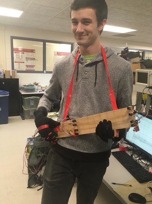
Figure 13: Our amateur bassist, Peter, with the final version of AirBass
Conclusions
Future Improvements
Although the distance sensor did perform as wanted, the calibration of the sensor could’ve been improved. The majority of our work with the sensor was finding the distance values at each fret and changing those values as we recognized the natural way a user would hold our prototype. As mentioned earlier, the human hand isn’t a flat, regular surface, so even tilting the playing hand slightly would affect the distance reading. Although we tried to alleviate this by extending the distance ranges for each fret, our final prototype did experience slight toggling between note frequency when fingers were placed on the boundary between two frets. A fix for this would’ve been adding multiple distance sensors, perhaps one for each string (to accommodate for the different readings at each string position) or a single one at the other end of the neck of the guitar (for calibrating against the difference of the two recorded values). Another fix would be to add a software median filter when reading the distance from the sensor. In the case where the sensor is inconsistent, not the user, a median filter would find the true distance the users hand is placed better than our averaging filter because our averaging filter cannot properly respond to incorrect spikes or valleys in the signal.
The flex sensor glove experienced hysteresis when flexing or unflexing each finger, meaning that the user had to fully unflex a finger to un-pluck it. This could’ve been remedied by adjusting the thresholds of the Schmitt trigger so that a partially un-flexed finger would be enough to drive the output high. Not only would this prevent the user from having to strain their individual fingers, but it would also be more authentic to the plucking motion of the glove. Additionally, moving the glove sometimes caused the soldered circuits to pop out pins. This was because the glove was connected directly to the glove with solid core wire. One fix could be switching to stranded core wire, which is more pliable and would put less stress on the soldering and header pins on our board and additional circuits. Another (more complicated) fix would be replacing the direct connection between the glove and the board with a wireless connection, as the only messages needed to be transmitted from the flex sensors are if they’re flexed or not. This would make AirBass even more similar to an actual guitar by keeping the guitar and human relatively separate.
For the physical layout of the sensors on the plank, the beam break sensors could’ve been placed in a hollowed out section of the wood (with the receivers and emitters were visible) and farther away from the last fret. This would give the users enough wiggle room to comfortably place their hand on the last few frets without stressing about the way their hand faced the ultrasonic distance sensor or potentially knocking over the beam break sensors.
An idea we toyed with at the beginning of the project was reducing the number of emitters, since the outputted IR signal coned out and could be received by more than one receiver by the time it reached the other end of the neck of the guitar. Ultimately, we decided to go with emitter-receiver pairs that were angled away from each other, but reducing the number of emitters and still working with the angle of the emitters/receivers may have enabled us to decrease the width of the strings. This would let us shrink the width of the wooden plank and make reaching the farther strings more possible, especially for those players with disabilities or smaller and/or less nimble hands.
Lastly, although the harmonics used on sine_table_harmonix
produced a string-like sound, the difference between a real bass guitar
and AirBass could’ve been slimmed down even more. Implementing the
Karplus-Strong algorithm when producing our DAC output has been proven
in other projects to make a sound that could be mistaken for the
physical plucking of a string. This would’ve turned our synthetic
bass guitar sounds into notes with more of the richness and cadence
of a true bass guitar string.
Intellectual Property
As far as we know, there are no intellectual property issues with our project. We used public datasheets for the sensors, designed our own circuits, and built off of code from our previous lab solutions. Though we did use references and resources to check our hardware and software implementations, nothing was directly copied without significant changes. We technically reverse engineered a bass guitar, but didn’t copy any specific guitar manufacturer’s layout or functionality with the implementation of AirBass. Instead, we worked with the general concept of a bass guitar, which isn’t covered by any patents or trademark issues.
A cursory search of the USPTO database doesn’t pull up a similar “air guitar” design with the sensors and software algorithms used. Therefore, there are patenting opportunities, if we so choose to pursue them. Our project could also be publishable, especially if the aforementioned modifications were made.
Ethics
As a team, we fully complied with the IEEE Code of Ethics. We’ve tried to design in as ethical and sustainable a way as possible, while also avoiding conflicts of interest. When writing our proposal, we strove to make realistic goals—these goals were ultimately achieved with our final product. We’ve designed AirBass to not require any electrical or software experience, so that the user doesn’t endanger themselves when using our product. All resources used have been cited below in References, as we wouldn’t have been able to finish our project to the degree that we did without them. All team members and users of the product were and are treated fairly, during both the construction and testing of AirBass. Overall, this was an ethical pursuit, as defined by IEEE.
Safety and Legal Considerations
There are no parts of AirBass that could physically or mentally injure someone. All voltages are kept as low as possible and all wire/solder connections are separated from the user, whether by electrical tape, wood, and/or wool (not with a conductive material). The sound produced by AirBass can be controlled in volume using the knob on the speaker, so the user can ensure they don’t play too loudly. No images or lights are used, so photosensitive or colorblind people won’t put themselves at risk of using AirBass incorrectly.
No radiation, transmission, conductive surfaces, or automobiles are involved in this product, nor any other hardware or software that is overseen by regulations.
Appendix
Appendix A - Approvals
The group approves this report for inclusion on the course website.
The group approves the video for inclusion on the course youtube channel.
Appendix B - Commented Code
Appendix C - Schematics
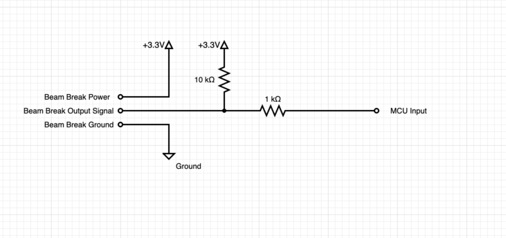
Figure 14: Circuit diagram for the beam break sensors
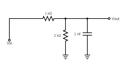
Figure 15: Low pass voltage divider on the echo pin of the ultrasonic distance sensor
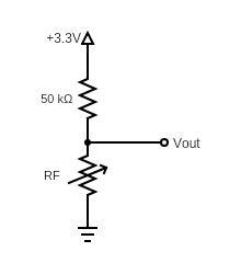
Figure 16: Voltage divider used for reading a varying output voltage from our flex sensor
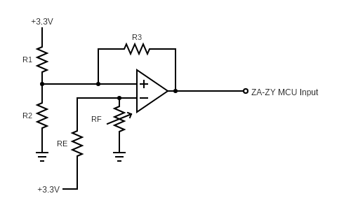
Figure 17: Full flex sensor, with MCP6242 amplifier, and resistance values R1 = 12K, R2 = 15K, R3 = 30K, RE = 50K
Appendix D - Parts List
| Part Name | Vendor | Part Number | Unit Price | Quantity | Total |
|---|---|---|---|---|---|
| IR Beam Break Sensor | Adafruit | A2167 | $1.95 | 4 | $7.80 |
| Flex Sensor 2.2" | SparkFun | SEN-10264 | $8.95 | 4 | $35.80 |
| Ultrasonic Distance Sensor | SparkFun | SEN-15569 | $3.95 | 1 | $3.95 |
| Amplifier | ECE Dept. | MCP6242 | $0.36 | 2 | $0.72 |
| Audio Jack | ECE Dept. | $0.95 | 1 | $0.95 | |
| Big Board | ECE Dept. | $10.00 | 1 | $10.00 | |
| Large Solder Board | ECE Dept. | $2.50 | 1 | $2.50 | |
| Small Solder Board | ECE Dept. | $1.00 | 2 | $2.00 | |
| MCU | ECE Dept. | PIC32MX250F128B | $5.00 | 1 | $5.00 |
| I/O Expander | ECE Dept. | $5.00 | 1 | $5.00 | |
| Lab Speakers | ECE Dept. | $2.00 | 1 | $2.00 | |
| Jumper Cables | ECE Dept. | $0.10 | 50 | $5.00 | |
| SIP Header/Socket | ECE Dept. | $0.05 | 18 | $0.90 | |
| Board Power Supply | ECE Dept. | $5.00 | 1 | $5.00 | |
| Resistors/Capacitors | ECE Dept. | $5.00 | 1 | $5.00 | |
| Wood Plank | Lowe's | $3.50 | 1 | $3.50 | |
| Glove | Lowe's | $2.00 | 2 | $4.00 | |
| Corner Joint | Lowe's | $0.75 | 1 | $0.75 | |
| Project Total | $99.87 |
Appendix E - Work Breakdown
Peter
- Brainstorming implementations and writing preliminary software for reading break beams, ultrasonic distance sensor, flex sensors
- Positioning break beams to minimize interference and produce reliable readings
- Setting up state transitions for amplitude envelope, testing by outputting and scoping this amplitude on a DAC channel
- Implementing Schmitt Trigger, selecting appropriate resistances and testing initial implementation
- Soldering the four Schmitt Trigger circuits
- General packaging for our final implementation: constructing flex sensor glove, drawing lines for positioning of beam breaks, taping down components, twisting wires, soldering connecting components & audio low-pass filter, etc.
- Calibrating thresholds for distance sensor in software for each string
Caitlin
- Brainstorming implementations and writing preliminary software for reading break beams, ultrasonic distance sensor, flex sensors
- Testing break beam sensors for reliability due to distance/angle for the emitter and receiver pairs
- Setting up and debugging state transitions for amplitude envelope, testing by outputting and scoping this amplitude on a DAC channel
- Implementing Schmitt Trigger, selecting appropriate resistances and testing initial implementation
- General packaging for our final implementation: constructing flex sensor glove, drawing lines for positioning of beam breaks, taping down components, twisting wires, soldering connecting components, etc.
- Calibrating thresholds for distance sensor in software for each string
Jackson
- Brainstorming implementations and writing preliminary software for reading break beams, ultrasonic distance sensor, flex sensors
- Positioning break beams to minimize interference and produce reliable readings
- Worked on Implementing Schmitt Trigger by selecting appropriate resistances and testing initial implementation
- Soldering the beam break circuits on protoboards and laying out components on the wood
- Wrote the initial logic for the sensor array to determine which note is played when
- Calibrating thresholds for distance sensor in software for each string
References
- Schmitt Trigger References
- Flex Sensor Datasheet
- Amplifier Datasheet
- Ultrasonic Distance Sensor References
- Beam Break Datasheet
- Timers & Input Capture
- Additive Synthesis
- Big Board I/O
- Development Board, SPI & DAC