System
Description
Form Factor
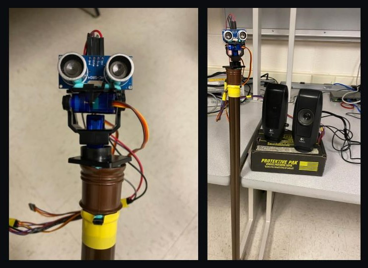
We have designed the AroundSound as an attachment on top of a walking stick or a staff. For a personal navigation aid for the visually impaired, we wanted the device to be something that the user can keep physically close to them at all times. The proximity to the user was also important for the efficacy of the navigation so that the device could almost “see” from the perspective of the user itself.
During our initial brainstorming, we considered a few wearable forms for the device, including a hat attachment, a tie, or a belt, all placed at the user’s axis of symmetry in order to provide more appropriate mapping of the surroundings. We had also considered using an array of sensors for a complete mapping.
Finally, we decided to go with the current form factor of a walking stick head with a movable sensor. This is at a more appropriate height (waste-level) for detecting almost all obstacles that might come in the way of the user, and it also provides a free-ranging mount for the distance sensor. Moreover, a walking stick is a commonly used assistive product used by visually impaired people, so the mental cost of adoption will be insignificant. Now, whenever the user wants to get an idea about their environment, they can place the stick in front of them and press a button to start the scanning process, which tells them exactly how far things are in every direction, through sounds coming from that direction. The placement of the button on the stick helps them always keep the stick facing forward (or any direction they choose). The images below display the final prototype of AroundSound we created and demonstrated.
Sound Production
AroundSound works by manipulating the user’s inherent ability of sound localization, i.e., their ability to identify the location or origin of a detected sound in direction and distance, by producing three-dimensional audio. Each time the button is pressed, a six second sound sweep with seven distinct beeps is played indicating the distance of objects at different angles within the field of view.
Sound Generation
The beeps are played through the 12 bit dual channel MCP4822 DAC which allows us to communicate with the PIC32 microcontroller via an SPI interface. In the code, we configured DAC A to be used for the left ear and DAC B to be used for the right ear. The basic beeps are implemented using direct digital synthesis (DDS) that uses sine wave bursts to create a digital sound signal. The DAC then converts this digital waveform into an analog waveform so that it can be heard through speakers connected to it. The frequency and amplitude approximations for DDS are done using frequency modulation (FM) synthesis, which modulates the frequency of the sound to improve its quality. Because of the limited compute power offered by the PIC, it was necessary to optimize these approximations to be able to produce sound at a sampling rate that makes the beeps sound pleasant to the ear. This means that all the sound synthesis related computation that occurs inside the timer ISR running at 20KHz, needed to complete in a reasonable number of cycles. For this, we used the _Accum datatype for all decimal values and calculation (e.g. amplitude and frequency). The _Accum is a fixed point value whose operations are much faster than the default floating point data type. We also reduced the number of calculations performed by predetermining some fixed values such as 2^32/44000 used in DDS.
The basic waveform equation that we used for FM synthesis is
wave = envelopemain * sin(Fmain*t + envelopefm*(sin(Ffm*t)))
with the following exponential function for each envelope
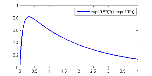
envelope = Ao * e(-dk_rate*t) * (1 - e(-attack_rate*t))
where dk_rate and attack_rate are the fractional changes in amplitude per decay sample. These exponential functions are calculated as first-order differential equations each time there is a timer interrupt. Modulating the attack and decay rates for the main and frequency-modulated envelopes changes the quality of the sound. For significant amplitude, the attack time should be much shorter than the decay time, so that the amplitude reaches its full output level quickly and decays to lower levels slowly as shown in the figure below. This is especially true since we did not add any ‘sustain time’ that would hold the amplitude at its full output level for a set period of time before starting to decay.
Following the above logic, we set the parameters as follows to obtain a string-like sound:
- attack_main = 0.001
- attack_fm = 0.001
- dk_main = 0.90
- dk_fm = 0.80
- F_main = 1
- F_fm = 3
Three-Dimensional Audio
These basic beeps are made three-dimensional based on the duplex theory of sound localization by the human auditory system, which states that since human ears are on different sides of the head and thus have different coordinates in space, the distances between the sound source and ears are different. This results in time and intensity differences between the sound signals that reach the two ears. These differences are called Interaural Time Difference (ITD) and Interaural Intensity Difference (IID) respectively.
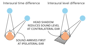
ITD is a direct result of the difference in the distances that the sound wave has to propagate through in order to reach either ear. Sounds produced on the right side reach the right ear earlier than the left ear. Based on the angular position of the acoustic source θ with respect to the center of the head, the head radius r which we calculated to be 8 cm on average, and the velocity of sound c, the difference in the distances is approximated to be 3*r*sinθ. We then used the following formula to calculate the ITD in units of cycles.
ITD = 3 * r * abs(sin θ) / c
IID is highly frequency dependent and is explained by the shadowing effect of the human head and ears. Sounds produced on the right side are louder to the right ear than the left since the right ear and the head act as barriers between the left ear and the sound source, absorbing some of the sound waves. IID increases with increasing frequency and is modelled as
IID = 1 + (f/1000)^0.8 * abs(sin θ)
With these equations, the ITD and IID are both zero when the angular position of the acoustic source is zero, i.e, the source is straight ahead and hence at an equal distance from both ears. They are also symmetric along positive and negative angles in the field of view. For example, ITD is the same for θ = 60 and θ = -60. These calculations are done within the sound thread and their results are stored in global variables for use within the timer ISR. In the ISR, the closer ear is determined by the sign of the angle θ. If θ is positive, the sound is coming from the left side and the left ear must hear the sound earlier and louder than the right ear. The reverse is true for a negative θ. For this, the main and frequency modulated phase and sound wave calculations for the farther ear are started ITD cycles after those for the closer ear. This difference in the number of cycles is maintained by a sound counter within the ISR. Before writing the sound wave to the appropriate DAC channel, the amplitude of the farther ear is scaled down by the IID attenuation. The angle θ is controlled within the program in the sound thread and mapped to the position of the servo motor in the servo thread.
Distance Perception
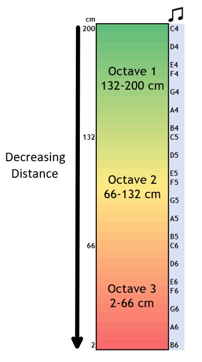
Three-dimensional audio implemented as explained above enables the user to determine the direction of origin of the sound. The second aspect of audio in AroundSound is to enable proximity perception of objects in these directions. This is done by splitting the entire range of distances (2 cm to 2 m) into smaller sub-ranges, and mapping each sub-range to a distinct frequency. For a pleasant sound experience, we mapped these sub-ranges to musical notes of different frequencies over three octaves. Starting at the note C4 for the longest distance (2 metres) and going up to the note B6 for the shortest distance (2 cm), there are 36 distinct notes, each mapped to a different sub-range. This results in sub-ranges of length 5.5 cm which is fine-grained enough for accuracy while at the same time slightly coarse-grained to not confuse any user. Each octave covers a range of 66 cm as shown in the figure below. Higher frequencies (red region in the figure) are meant to intuitively warn the user that there is an object very close to them, while lower frequencies (green region in the figure) indicate safety as the object in that direction is farther away.
With all of the above implementations, we obtained a six second sweep which can reliably inform a visually impaired user of the direction and distance of objects around them. We connected the DAC output of the PIC32 microcontroller to speakers which in turn were connected to headphones that were worn by the user. This was done because the speakers had an in-built gain circuit that amplified the sound making it more clear and easier to perceive. To make the device more mobile, we can implement a gain circuit using an LM386 sound amplifier that would eliminate the need for external speakers and allow us to connect headphones directly to the DAC output.
Distance Measurement
The second key subsystem in the project was the measurement of the distance of objects surrounding the user. In order to create a mapping of the user’s environment, the device had to measure the distance of obstacles at multiple points in the visual range. In order to achieve this, we have used the HC-SR04 Ultrasonic distance sensor in AroundSound. This is one of the most common distance sensors available in the market and is used by a variety of projects.
The HC-SR04 measures distance of any object in front of it by transmitting an ultrasonic sound pulse (above 20 KHz) and detecting the receipt of its echo from the object. This is a passive sensor, i.e. it doesn’t directly measure the distance and communicate that to the microcontroller through a protocol like some of the sophisticated Time-of-flight sensors. Instead, the microcontroller needs to manually send the sound pulse through the sensor, and measure the duration of the echo. The sensor is designed to measure distances from 2 cm to up to 4 m with an accuracy of 3 mm.
Circuit
The HC-SR04 sensor operates with 4 pins: 5V input, ground, trigger, and echo. In our system, we power the sensor through the VIN and GND pin on the SECABB. The TRIG pin is a general output pin, so we use pin RA2 on the development board. For the ECHO signal, since we need to measure the duration of a pulse, we use an input capture module on the PIC32 from pin RPB13 on SECABB.
Software Implementation
As described above, the distance sensor consists of one TRIG input and one ECHO output pin that are used to determine the distance of an object. In order to take one instance of the measurement, the following steps take place sequentially.
- The TRIG pin of the sensor is pulled up by the microcontroller for 10 us.
- The sensor then transmits 8 sound pulses at 40 KHz, which serves as the “ultrasonic signature”, helping it distinguish the sound from other sounds in the environment.
- Once the 8 pulses have been transmitted, the ECHO pin is set to high by the sensor. This output stays high until the sensor receives the reflections of all the 8 sound pulses, after which it is pulled back down.
- The microcontroller measures the duration for which the ECHO pin was set high, which is then used to measure the distance according to the following formula:
distance_cm = (0.034 * duration_us) / 2;, where 0.034 cm/us is the speed of sound in air.
This sequence has been illustrated in the animation below.
In order to perform this on the PIC32 microcontroller through the development board, we used the IO pin A2 to control the TRIG pin. In the code, we configure pin A2 as a digital output, and inside the distance thread, the pin is set to high when there is a need for distance measurement. Since it is essential for the TRIG pin to be high for exactly 10 us, we used a blocking delay in code using nop statements. With the microcontroller running at the default 40 MHz clock speed, we needed 400 nop statements to create a delay of 10 us.
For the precise measurement of the duration of the reflected pulse on the ECHO pin, we used the input capture module 1 on the PIC32, connected to pin RPB13 on the SECABB. The input capture was configured with timer 3 as a free-running counter to trigger an interrupt at both the rising and the falling edge of the ECHO pin. This allowed us to obtain the precise time duration from when the ECHO pin is set to high to when it is pulled back low by the sensor. Since this duration of the ECHO pin can be up to 40 ms, we needed the timer to be able to measure up to 40 ms in its 16-bit register, so we set the timer to run at 156.25 KHz (prescaler of 256), which gave us a resolution of 6.4 us. From the above distance formula, this gave us a distance resolution of 1 mm, which is lower than the sensor prescribed resolution of 3 mm, therefore avoiding any loss of accuracy.
Servo Actuation
The previous subsystems are responsible for generating 3D audio and detecting the distance of obstacles from the user respectively. The final key subsystem for our product is an SG90 servo “gimbal”, which sweeps over an angular range and uses the HC-SR04 ultrasonic sensor mounted atop the platform for acquiring distance values at discrete points over the sweep. The SG90 is a common servo motor used in hardware projects that permits 180 degrees of rotation that can be controlled by an input PWM pulse from any microcontroller.
We defined a range of -60 degrees to 60 degrees as AroundSound’s “field of view” - we believe that this fairly accurately mimics the lines of sight in humans that are used to process visual information regarding one’s surroundings. We actuate the servo to move through seven points in this 120 degree angular sweep, each at distinct 20 degree intervals. We use the output compare module on the PIC to generate a PWM signal, which is adjusted to attain the desired angle. We principally rely on open-loop control to ensure that our servo is actuated correctly - a factor to consider when building a newer version of the device would be to include encoders for ensuring that the angular position attained by the servo is correct.
Circuit
The SG90 servo operates with 3 inputs - power, ground and PWM. In our system, we power the servo through the 3.3V and GND outputs on the SECABB, driving the required power through the servo. Ideally, the voltage level of the sensor should be around 4.8 to 6 volts, but our testing showed that the 3.3V power and logic level would drive the servo appropriately for our application. The PWM pin is connected to RB9 on the SECABB for receiving PWM signals from the output compare module on the PIC32 - this is driven by 3.3V logic as well. The circuit schematic is shown below.
Software Implementation
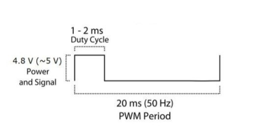
As stated above, we wanted to have a mechanism by which we could achieve discrete points at which we can sample the distance of an obstacle from the user. In order to achieve this control, we had to experiment with the PWM pulse we were sending to the servo - the servo accepted a PWM with 50Hz frequency, and required a duty cycle of around 5-10% to achieve desired angular position. Specifically, a 1ms pulse indicated a left position (-90), a 2ms pulse indicated a right position (+90) and a 1.5ms pulse indicated a centered position (0). The image below shows the PWM signal for the servo.
Based on this understanding of the PWM range required for the servo, we use the output compare module on the PIC accessed through B9 to set the desired PWM signal. The code setup for this system was quite simple and can be illustrated through the following steps:
- Initialize the pt thread for the servo execution depending on whether the sound thread has finished executing.
- The negative 60 degree position is calculated as a PWM duty cycle of 2500, with the total period set as 50000. Once the servo thread is initialized, increment the duty cycle by 500 for moving to the next position.
- Keep incrementing by 500 until the positive 60 degree position (PWM duty cycle of 5500) is reached.
- Reset the servo position from positive 60 to negative 60 degrees, and halt the execution of the program until the button is pressed again.
Since the PIC32 operates at a frequency of 40MHz, we needed to scale the timer to ensure that the PWM period can be used to set up a frequency of 50Hz. We use a prescaler of 16 on timer 2, which configures the timer to execute at 2.5MHz, and the PWM period of 50000 dictates the 50Hz frequency required for the signal.
System Flow
With all the subsystems established as given above, we needed to define a system for their execution to ensure that all the processes were executed in a definite order to produce the desired result. Each system was encapsulated in an individual protothread and each protothread’s execution is made conditional upon the completion of the previous thread. The following diagram captures the timeline of the system execution:
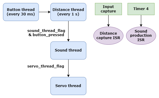
We first check whether the button has been pressed - this thread executes every 30 ms. We use an FSM to confirm whether a button is pressed or not, and set flags to allow the sensor to acquire distance, the sound to be generated and the servo to rotate in that order. Once the servo has completed rotating to its final position, we send it back to its initial state and clear the flag set from pressing the button, which prevents the program from executing until the button is pressed once again. Using this process of activating each protothread conditionally gave us complete control over our software, ensuring that each subsystem ran in a desired sequence and was able to terminate cleanly. In addition, the modular structure of our code ensured that we could meet the timing constraints posed by the DDS algorithm as well as the signal frequencies required by the ultrasonic sensor and the servo motor without running into conflicts.
Our design process was iterative - we started by building out the 3D audio element of our project first, since we anticipated that aspect would be the most time consuming. Following an initial implementation of the 3D audio system, we progressed to simultaneously implementing the control for the servo motors and testing with our distance sensors - we were able to complete the tests with the servo motor quickly but needed some additional time to select and program the software for controlling the ultrasonic sensor due to unsuccessful results from our other sensors. Since this ensured that the baseline details of our project were complete, we moved onto refining our audio generation, implementing a more robust system for creating a perceptible audio difference between ears, including FM synthesis for generating cleaner tones and designing the frequency to distance mapping that forms the critical part of our project. Finally, we tied together all the software modules and checked that our conditional thread operation produced the desired output from our device, and completed the wiring and mounting for our hardware design before our project demonstration.