
|
|
Hardware
The hardware for this project had three main components: laser gun assembly, detector unit, control pad. The detector unit’s function was to simply detect a laser pulse over a small area sent by the laser driver circuit on the laser gun assembly. In reaction to this detection the control pad would keep correct score, play a short sound to indicate a hit, and transmit a successful hit via an RF frequency to the other player’s control pad where it would be received and displayed. These three components joined together would complete the laser transmission, detection, and control for use in a typical laser tag environment; however, due to the multiplayer nature of the game, each hardware component had to be duplicated for the second player to use. Our general plans was to have a stand-alone laser gun driven by its own independent power source, and have this laser work in conjunction with a combined laser detector and control module. This would allow players to not have the dreaded cable extension from the laser gun to the detector unit that would often impede the games progress due to its incontinent placement. All three components were designed and tested for minimal power consumption as all of the units would be run on standard AA battery cells.
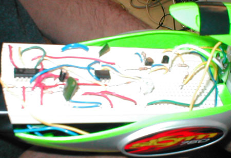
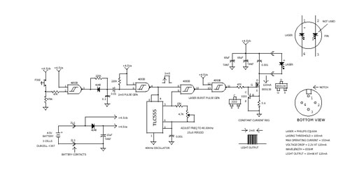
The laser gun portion (see picture above) of the project was the first component to be built. We had clear goals for this portion of the hardware: has to have an independent power supply, has to emit only short control laser pulses, has to have low power consumption, has to control and drive the visible NVG Inc.38-1003-ND 650 nm laser module in the proper manner. Once parts for this element were gathered together, an understanding of the schematic had to be reached in order to modify it to our desired specifications. We quickly parsed the circuit into three main sections. The first section of the circuit was built with two CMOS 2 input NAND Schmitt triggers to create the general time scale for how quickly the user could pulse the laser. In our case, we modified the RC time scale to result in an approximate time of 700ms, after analyzing many trial runs. The second part of the circuit was the generation of a standard transmitting 40 kHz wave that was to be superimposed on to the 700 ms wave created in the first stage. The second stage comprised simply of a TI LM2904 555 timer whose frequency could be adjusted with a 4.7 k-ohm trim potentiometer. In the end, the frequency we used was 35 kHz. The third stage was just the power stage as a PN2222 NPN transistor and a 2N7000 N-channel Enhancement mode FET were used in tandem to drive the laser at a constant current and a safe voltage level. After having thoroughly understood the schematic the circuit was built and tested on standard protoboards where no problems were found. To finish up the laser gun portion of the project we had to encase the laser driver circuit and the laser load. We modified two super-soaker cases to hold our boards and had the mechanical trigger switch electronically connected to board in the appropriate locations. Pop in three AA batteries and the laser gun worked like a charm.
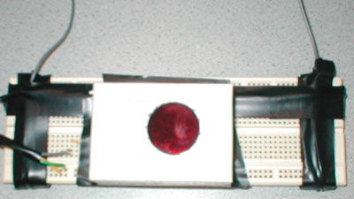
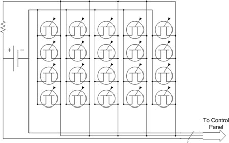
In logical sequence with the transmitter having been built, the next component to be constructed was the detector (see picture above). It was in this stage that we ran into many concerns and issues. First off, we had to find and purchase detectors that would be cheap and would detect a red visible laser pulse. This was hard to come by and we eventually had to settle for some PN168 NPN phototransistors that were 4mm by 3mm. Hence, due to their small size we had to buy multiple to create an array of these transistors in order to have a detection area that would be reasonably large. Having received these parts early on, we ran into our major issue in this project after the laser gun had been built. It became quickly clear that our cheap and small phototransistors were having a problem with ambient light. It turns out that they were always getting turned on in the presence of even small amount of indoor light or sunlight. Therefore, they were never able to correctly detect the laser pulse, which was also in the visible spectrum. We tried to construct many unusual circuits that could bypass this problem via band-pass filters. Even the use of cheap red transparency sheets did not do the job. Thus, 3 days before the project was due we received two specialized 650 nm band pass filters. These filters were built to pass only wavelengths from 640-660 nm, which was ideal for us. This filter when applied to our array of PN168 worked very nicely by blocking next to all of the ambient daylight and passed only the signal of the laser we desired.
With all the laser and
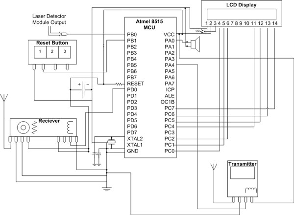
detector working, the user interface was missing link. The elements used in
this stage were: Atmel 8515 RISC MCU, 16x2 LCD, pushbuttons, standard speaker,
and RF transmitter/receiver pair (Radiotronics RCR-433-rp). The detailed circuit
layout is as shown below.
The MCU was used to control all of these components via software programmed
onto the chip using an STK500 development board. The main function of the chip
was to take logic high logic levels from the detector circuit (indicating a
hit) and in response play a short sound, increment the users score on the LCD,
and transmit the successful hit back to the other player so he/she knows the
correct score. Due to the mobile nature of the project, we quickly decided to
run the Atmel 8515 stand-alone with all the other components on one protoboard
that would eventually attached to the players’ wrists. Few difficulties
were run into in this part of the project, but one of the more troublesome ones
was the fact that out transmitter was a surface mount component leading to nightmare
soldering jobs. The other major problem encountered was the fact that our fairly
cheap receiver/transmitter pair would pick up great amounts of noise if the
transmitter was not outputting a signal. This had to be fixed otherwise the
MCU was continually receiving input from the other user that he or she had been
hit, resulting in the score of both users incrementing themselves. Hence, the
way we went around this issue was to have the transmitter always registering
an output to avoid any possibility of noise to be picked up by either of the
receivers. Aside from these hurdles, at this point we had successfully built
the large amount of hardware needed to complete the project. Add on a few harnesses
and some good electrical tape to mount these units on to the players, and you
would have a fully functional customized sniper tag system.
 |