Hardware Design
Our implementation of Jezzball used two MCU’s, one to connect to the TV, and another to the mouse. They communicated with each other using the SPI. The overall circuit diagram is found in our Appendix.
Television Hardware
The TV setup is the same as in our video game lab. We used PORTD.5 for generating the sync signal, PORTD.6 for the video signal and PORTB.3 for input of sound into the TV. The two video signals are summed together in the following manner:
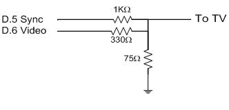
The Input to the TV is through standard RCA connectors with one end stripped to allow us to connect directly to the lines.
Mouse Hardware
To control the game, we used a PS/2 optical mouse. The mouse is connected to our MCU by way of a PS/2 connector that we scrounged up from a previous year’s project. The mouse and connector have the following pin outs:
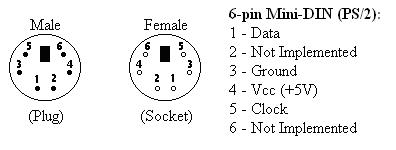
Figure taken from: http://www.computer-engineering.org/ps2protocol/
We connected the data line to PORTA.0 and the clock signal to PORTA.1 and powered the mouse with the MCU power. Communication with the mouse is done by sending back and forth data packets. The mouse MCU sends packets of 12 bits: 1 start bit, 8 data bits, 1 parity bit, 1 stop bit, and 1 acknowledge bit. The mouse sends packets of 11 bits, including all the bits mentioned earlier, minus the acknowledge bit. When the mouse sends data, it sends 3 bytes of data seen below.
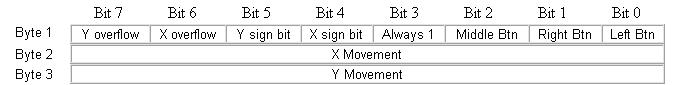
Figure taken from: http://www.computer-engineering.org/ps2mouse/
The x-direction and y-direction is encoded using 9 bits in two’s-complement notation. We initialize the mouse by resetting it. This entails sending to the mouse 0xFF, then reading the acknowledge from the mouse (0xFA). We then send the mouse to remote mode by sending 0xF0, and again reading the acknowledge from the mouse. The remote mode is used so the mouse only sends data when requested by the MCU sending a 0xEB byte to the mouse. We then pull the clock low for 100ms to inhibit any transmission.
To request data from the mouse, we send the mouse the request byte. We then wait for the acknowledgement followed by the three data bytes, which we convert to the x and y-directions and the mouse button status. This procedure is explained in the Software Design section.
Further restrictions on mouse timing, as well as a step by step implementation procedure can be found at the mouse protocol website found in our references.
Software Design
The four most important parts of the code were:
- Mouse code
- SPI code
- Jezzball game code
- TV video code
Mouse Code
The implementation of the mouse was done by adapting code from the previous years Paint Program with Mouse Control by Steven Keiper and Ragavan Mahedevan. We used their functions: mouse_send, mouse_read, update_cursor, poll_mouse, and reset_mouse. The mouse methods were originally written by Chee Ming, Chaw and Elaine Siu for their TV Minesweeper.
Sixty times every second or every frame, we poll the mouse for data and update the cursor position on the Mouse MCU, and send off the three bytes of mouse data to the TV MCU. Polling the mouse and updating the cursor position is done when the TV MCU is generating the viewable video signal to the TV.
The poll_mouse method, sends a byte to the mouse requesting data, reads the acknowledgement from the mouse, and then the three data bytes, every time we wanted input from the mouse. In the modified update_cursor method we save the last cursor position, update the new cursor position from the mouse data that we’ve received, and error check to make sure the mouse has stayed within the bounds of our game. We then shift the cursor position to the right one byte to reduce its sensitivity and convert. This is purely for ease of game play. We also read in the state of the mouse buttons to transfer over to the TV MCU.
After the TV MCU receives the data, we had to debounce the mouse buttons or else we would detect multiple button clicks for each valid user click.
Serial Peripheral Interface (SPI)
To communicate between the two MCU’s we used the built-in SPI to allow for fast and synchronous data transfer. The SPI defines a master and slave MCU, with the master defining the clock rate. Although this allows for simultaneous transfers and receives from both MCU’s, we only needed to transmit data for mouse position from the mouse MCU to the TV MCU. This is done by first setting up the SPI Control Register (SPCR) and SPI Status Register (SPSR) to disable the interrupt (SPIE), enable the SPI (SPE), set either master of slave (MSTR), and the clock frequency(SPI2X,SPR1:0).
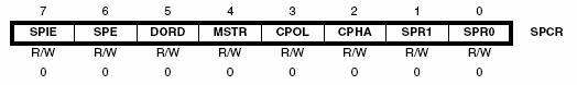
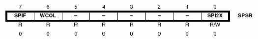
Figure: SPI Control/Status Registers (copied from Mega32 DataSheet)
We also setup DDRB port pins to be the appropriate inputs and outputs.
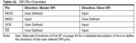
Figure: Pin Configurations for SPI (copied from Mega32 DataSheet)
With the MOSI, SCK, and SS pins on the master and MISO on the slave as output, and the rest as input.
We initialize the SS pin on the master high to put the MISO in the slave in tri-state so no transfer is possible. The master initiates a transfer by pulling the SS pin low, and loading a byte into the SPI data register (SPDR). We then loop until the transfer is complete by checking the SPI Interrupt Flag (SPIF) in the SPSR register, and pull the SS pin high to synchronize the slave. We then read the data sent to get our mouse data, which will also clear the SPIF bit. We repeat this procedure for all three bytes of data. On the slave side, we load the SPDR with the first byte we want to send, and loop until it is sent by checking the SPIF in the slave MCU. We then read the byte sent over from the master to clear the SPIF bit, and load up the next byte to send
Jezzball game code:
The Jezzball code was implemented on the same MCU that was connected to the TV. Most of the MCU processing power was used to generate the signals to the television but once it gets to line 231 (off the viewable area) there is time to process the logic to implement the game and update the states.
Our game is organized into four main areas which have many sub topics:
- Main Menu
- Start game
- Sound
- Lives
- High Score
- Game Play
- Ball Movement and Generation
- Cut Detection and Application
- Detection and Filling in of Legal Cuts
- Score Calculation
- Area Calculation
- Sound Effect Generation
- Cursor Movement and Placement
Main Menu
When we first get into our game we go to our main menu. Here is a screen shot of our main menu:
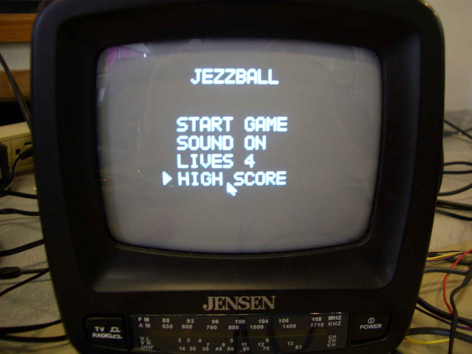
When the mouse cursor hovers over the a clickable area a triangle appears to the left of the menu item indicating that if the user clicks, it will select that option.
From the picture the different options available are:
Start Game: This button allows the user to start the game. It uses all of the options that have been set in the menu (such as sound on/off and the number of lives). The screen will be cleared and lines and text that are necessary for our game implementation will be drawn. The game will begin on level 1 (which has one ball).
Sound: This option allows the user to turn the sound on or off. This is for times where the sound gets too repetitive, or the environment requires silence.
Lives: We allow the user to set the number of lives. This can be for personal setting of their difficulty. Beating the game with 1 life is considerably harder than beating it with 5 lives.
High Score: If the user clicks this option it clears the screen and displays the current high score that is stored in EEPROM. When the user clicks again, the screen clears and the user goes back to the main menu.
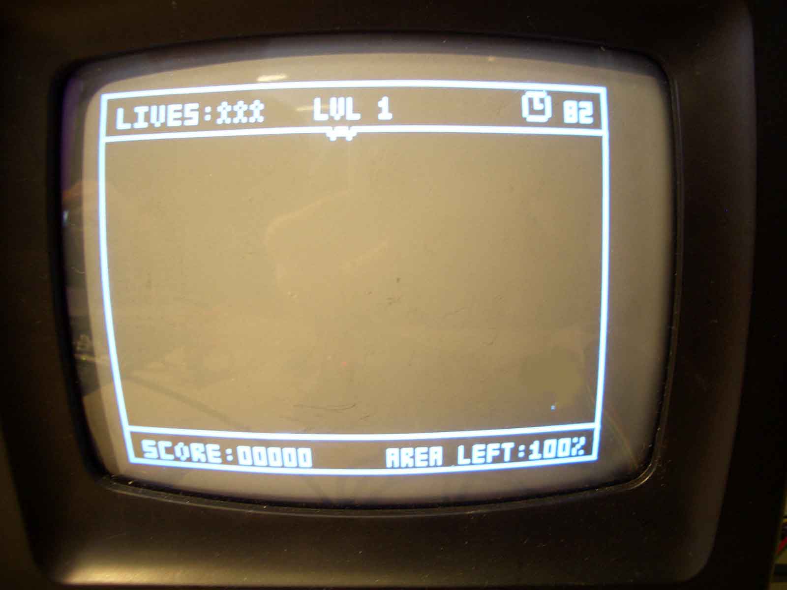
Game Play
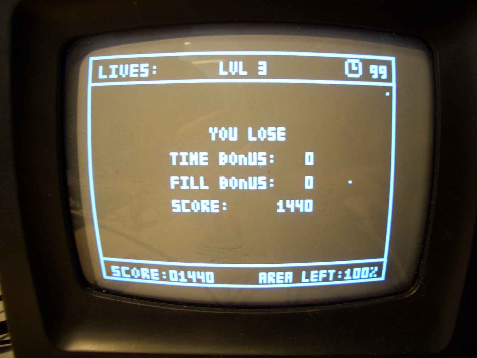
Our game playing area uses only the middle section of the screen. The top portion and part of the bottom portion is used to display information such as number of lives left, time left (for bonus points calculation), current score, and the percentage of area left. See the screen shot below
The different aspects of the game are broken into the following sections:
Ball Movement and Generation:
We allow up to 10 balls on the screen at once (anymore and the game would be unplayable. We have tested to make sure it is possible to make successful cuts with 10 balls on the screen; it just is pretty hard). Each of the balls always travel at 45 o angles which means that the x and y velocities can either be -1 or 1 pixel/frame. This allows four different directions for each ball. We generate the ball positions and directions randomly using the rand() function before each level. However, we initially found that since the seed is the same, the ball positions for each level are the same. We fixed this by setting the random seed before each level to a counter that we have within the timer 1 interrupt. This ensures a different seed before each level which makes the generation random.
We decided to implement an algorithm to handle the bouncing off of walls smoothly (not erase any part of the line it is bouncing off of). This allows us to not check boundaries to determine if a ball should reverse velocities (because the boundaries that balls are in are very dynamic in the game). We check whether certain pixels are filled in based on the current velocity and speed in order to determine which velocities to reverse (see our code in the appendix for the specific algorithm).
Cut Detection and Application:
We have the initial position of where the cut is generated from the mouse position. The cut goes in the current orientation (vertical/horizontal) of the mouse pointer and grows at a rate of 1 pixel/frame in both directions. The cut is successful if both ends of the cut manage to hit the end of the boundary. If the cut ever hits a ball or a ball hits the cut while it is moving the line is drawn over with black (to make it disappear) and the player loses a life. Our code checks each of the ball positions every frame and checks to make sure that they do not pass through the area of the line.
Detection and Filling in of Legal Cuts:
Once a cut has successfully completed, a new boundary is generated. This portion of code was tricky to implement. In order to fill in different parts of the boundary we needed to first have a method of storing each of the boundaries. Boundaries are determined by the user and change constantly as the user continually makes legal cuts. Since each cut has to cut across the screen in one direction, each boundary is rectangular in shape. Thus we used two points to represent each boundary (the top left and bottom right corner; this also limits the amount of memory used). It is only possible to have 10 different boundaries because each boundary must have a ball inside of it for it to remain (otherwise it should be erased). Since we have a maximum of 10 balls, we used a static size 10 array to store the boundary positions. Each cut has two endpoints. We use the endpoints to determine which boundary in question will be “cut”. From this information we generate two new boundaries and check if there are any balls that exist inside of the new boundaries. If there are, both boundaries are kept. If there aren’t then empty boundary gets filled in.
To fill in the boundary was also tricky. Because of the limited processing time available we needed to stagger the filling in of the specific boundary. Since it is staggered, it is possible for a two cuts to complete and require filling in at the same time. Thus we used a circular array that contained the boundaries that need to be filled in a “queued up” fashion. A separate function is called every frame that fill in one line at a time.
Score Calculation
We wanted to base the score with a scaling factor based on the difficulty of each level. The points generated per percent of area filled in are scaled by how many balls there are for that current level. There are also two ways to earn bonus points. There is a time bonus and a fill bonus. The time bonus is calculated by how much time is remaining on a current level. The timer starts at 100 for each level and goes down every second. Once the timer hits 0, the player will not lose but will not attain any time bonus. The fill bonus is calculated by how much extra percentage is filled in besides the required amount. To pass each level, the player must have less than 25% area to be filled in. The percentage is checked after each successful cut, so there is an opportunity to fill in more than what is required on the last cut. For every percent filled in that is over the required amount a bonus score is applied.
Sound Effect Generation:
The code that is used to generate sound is similar to the one in Professor Land’s example code in lab 4. It uses the timer0 square wave generator to make tones but has been modified to fit our purposes in the game. If the sound is set to be on, whenever the ball hits a wall or when a cut is hit by a ball a tone is generated. A few notes are also played when the player completes a level or when the player loses. The lose and win notes are stored in flash memory and played at the appropriate time.
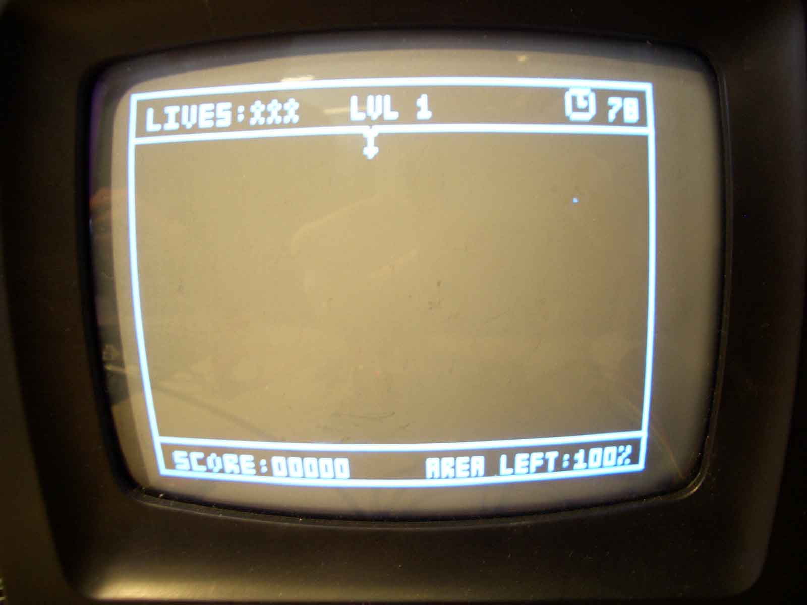
Cursor Movement and Placement:
The cursor placement and movement was tricky to implement because we did not want to erase any of the drawings on the screen or affect the ball movements. In order to do so we staggered the order of when the drawings took place and we stored the memory behind the cursor. Before any calculations were made we erased the cursor by putting back whatever the saved state that was previously at the cursor. This makes the cursor “invisible” to all other calculations on the screen. We then process the calculations as normal and at the end we save the state behind the cursor into memory and we draw the cursor on the screen. Another slightly tricky issue with the cursor was with the placement on the edges of the screen. We had two different types of cursors, the horizontal and vertical directions. The problem was with boundary conditions. The vertical cursor should be allowed to move closer to the side of the screen than the horizontal cursor (see screen shots below) because we store the cursor position by the top left of the picture object. We fixed this by alternating boundary conditions based on the current direction of the cursor and if the cursor is outside the boundary (when the user changes directions) it will automatically place the cursor inside the boundary. This was in addition to the error checking of boundary conditions in the mouse code.
Things we tired but did not work:
The original classic Jezzball draws two separate cuts, one going on either side of the orientation. This allows “half” a cut to succeed, which results in part of a line on the screen which can be used to trap balls and make new cuts with. Since we wanted to make our game as close to the original as possible, we spent many hours and days trying to develop the algorithms that would allow us this functionality. Unfortunately, we started running out of memory very quickly and running out of processing time for our algorithms. In addition, it was very difficult to come up with proper algorithms. For example, since every line can now exist on the screen, we needed to store every line that was complete. By connecting half lines, it is possible to generate complex rectangular polygons that need to be filled in. Given a set of points which define the rectangular polygon it is not trivial to determine if a ball lies within that area. It is also difficult to separate the area into rectangles to be filled in. Also, after all of this is complete, we still need to keep track of many lines are on the screen after part of them have been used for erasing. Because of these problems, we decided to scale back our design and only allow “complete” cuts. This simplifies the problem because now cuts will always be rectangles. This problem is not simple but becomes more manageable in terms of processing time and space.
We encountered many difficulties while we were implementing SPI since we did not have any examples of MCU to MCU communication to build on. Our first attempt manually tried to manipulate the SPI using interrupts by setting up two test programs, but we had trouble synchronizing the three bits (x-position, y-position, button press) between the MCU’s. We then tried using the spi functions provided in spi.h. This did not yield any good results as we could not even loop through one iteration of data transfer. We abandoned this implementation because we did not fully understand how this function worked, and could not find the c code for this function. Our third attempt was again at a manual implantation, but without interrupts. This time, we had more experience with the intricacies of SPI and were able to synchronously transfer data.
