|
|
|
| ECE 476: Accelerometer Mouse: Hardware Design | |
|
The hardware design revolved around two primary parts of the system: the PS/2 connection hardware and the accelerometer connections. PS/2 Hardware:The role of the PS/2 protocol in our system is to send mouse data to the PC and also to process commands from the PC to the mouse. To setup such an interface, we had to design both the hardware and software to running the protocol. The hardware interface of the PS/2 protocol stems from the 6 pin DIN connector that most people have on the back of their computer:
Figure-1: Mini Din Connector - Source: www.computer-engineering.org There are two types of DIN connectors. The male plug is the connector coming from the mouse, which fits into the female socket found on the host machine. Although the connector has 6 wires, only 4 are actually utilized for PS/2. The following pins configurations correspond to the diagrams above:
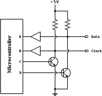
To connect our mouse to the PC, we took the PS/2 cable from an old mouse. We then matched the pins to the wires on the other end using a multi-meter in the lab. If we did not have the mouse, we most likely would have used the following parts from Digikey. Mini DIN Connector: 275-1103-ND $2.33 We next setup the open-collector interface required by the PS/2 protocol. An example interface is shown below: Figure-2: Open Collector Circuit - Source: www.computer-engineering.org An open-collector scheme is used to create two possible states in the system, either low or “high-impedance“. Both the micro-controller and the PC share these lines to communicate. In the figure above, A and B are outputs from the mouse, while C and D are treated as inputs. When either C or D are high, B & A will be force connected to ground respectively. However, when C & D are low, the actual values from A & B will be sent to the host. This scheme allows the PC to inhibit signals from the mouse at the electrical level. When inspecting our hardware schematic, one will see that we employed resistors instead of transistors in our scheme for simplicity. The choice of resistors is not terribly important. For the pull-up resistors (the resistors connected to 5V), the larger the resistance, the lower the power consumption but slower the switching. We decided on using 10 k Ohm resistors. The resistors connecting the input and output lines used 330 Ohm resistors. Note that the 5 volts needed can be taken from the MCU or the PS/2 Vdd connection itself. Accelerometer Hardware:The accelerometers were relatively easy to set up. Three MMA1260D and one MMA2260D were used. The MMA1260D is used to measure tilt along the Y axis (thus motion along the X axis) and measure button presses. The MMA2260D measures X axis tilt (i.e. motion along Y axis). The data sheets indicated that a low pass filter might be a good idea to use between the MCU inputs and the accelerometer outputs. Since we wanted to keep the design as simple as possible, we tested the connections without the LPFs and they worked just fine. We checked the signal using an oscilloscope and the noise was negligible. The signal is strong enough that the deviations caused by 60Hz noise are not strong enough to noticeably interfere with our readings. Figure 3 shows a schematic of the hardware connections. Figure-3: Accelerometer Hardware Connection Diagram Initially, we did all of our testing and programming using the STK-500 boards. When we transferred to the custom PCB board, we had some serious problems. Some of the soldered connections kept falling off, others just magically disconnected themselves. Since the green PCB board does not “hold on“ to solder (which is a good thing in some cases) it was very difficult to replicate the functionality of a white board (bread board) onto the PCB board. Eventually we got it to work. Considering how cheap the overall design is (only $18), we might design another board so each of us can take the project home. Physical DesignApart from the electrical design, the physical design also took some prowess. The major concern was how we could keep the X and Y axis measuring accelerometers perpendicular to each other. If the accelerometers are worn at an angle, the mouse would constantly drift. We decided very early on to not have a calibration button (or something along those lines) so using the mouse itself will not be a hassle. So, we needed to create a housing that would ensure that, if at least one of the accelerometers is properly oriented by the user, the other accelerometer would automatically orient itself. Initially, we cut out the corner of a cardboard box to create a right angle that you could wear over your thumb. Some electrical tape was used to pseudo-stick the cardboard to the thumb to keep it in place. Although this worked relatively well, the box eventually started slipping (as the thumb got a little sweaty) and it also got in the way of pressing the buttons (curling the middle and index fingers). So we did what any good engineer does in a case like this: look to the past to see how a similar problem was fixed. Velcro was the next logical step. We moved the cardboard right-angle to the palm itself (thus freeing the thumb and allowing more freedom for the button fingers), and used Velcro to pin it against the palm. If the side of the cardboard right-angle is laid perfectly flat against the inside of the palm, the top part of the cardboard right-angle automatically orients itself (during normal use) to be perpendicular to the gravity field. Furthermore, we were using rubber bands to secure the accelerometers to the button fingers, but this was very, very painful and lead to cold finger tips (due to reduction in blood circulation). We replaced the rubber bands with Velcro as well, and our fingers were happily clicking without fatigue. Figure 4 shows the physical layout picture. The arrows indicate the direction of gravity and whether it is negative or positive in that direction. Note: a dot indicates an arrow pointing out from the paper and a cross indicates an arrow pointing into the paper. Figure-4: Physical Layout
|
| Copyright © Aseem & Karthik 2005. | Design by Aseem Kohli |