|
|
|
| ECE 476: Accelerometer Mouse: Program Design | ||||||||||||||||||||||||||||
|
Accelerometer Software Design:
The ADC reads a voltage output from the accelerometer and compares it to a 5V reference, and outputs a function of the ratio of the two values to an 8 bit variable. Therefore, if the accelerometers read 0G, which is a 2.5V output, the ADCH value would be about 127. The MMA1260D (which measures the tilt along the Y axis) is used for X axis position and the MMA2260D (which measures tilt along the X axis) is used for the Y axis position. When the hand tilts left, the MMA1260D reads negative G values, so it outputs a voltage less than 127. This value needs to be converted into a signed version: the mouse_byte values take the signed values of the accelerometer (2's complement) and mouse_byte0 has bits that indicate the sign of the mouse_byte values (basically mouse_byte0 takes the 7th bit from mouse_byte1 and mouse_byte2 to indicate to the CPU whether the values are positive or negative). The same applies for the MMA2260D, which reads a voltage which is converted to a number less than 127 when the hand is tilted down and a number greater than 127 when the hand is tilted up. Getting the signed value is not as easy as just type-casting the unsigned char value of ADCH into a signed char value. The ADCH value needs to be calibrated first to the 0G value of 127. The most straightforward way to do this is to subtract 127 from the ADCH value (type casted as a signed char). Thus, negative values implied the hand was tilted to the left and positive values implied that the hand is tilted to the right. Furthermore, tolerance values need to be set for the tilt angles. People's hands shake. This cannot be avoided. But with tolerance values, small deviations from the hand's resting position can be ignored. Values +/- 6 from the resting value are thrown out for tolerance purposes (i.e. the variable's value is set to 0).
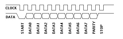
If these values are thrown out for the sake of tolerance, and then 127 is subtracted from the other values, the lowest value that will be is +/-6. This causes a problem: it creates a “jerky“ mouse pointer. The effect is less profound along the Y axis on the screen since a monitor's display is not as high. But the effect showed clearly on the X axis of the screen since it is wider. To compensate for this, instead of subtracting 127, we subtracted 132 (we came up with this number after trial and error). This gave us the smoothest scrolling without sacrificing speed. The more stringent the subtraction, the more the user would have to deviate their hand from the resting position to move the mouse farther. The less stringent the subtraction, the more “jerkiness“ the pointer would have. 132 gave us the best compromise between the two. The accelerometers mounted on the index and middle fingers, MMA1260D's as well, measured the acceleration of the fingers as you curl them inwards. These accelerometers are used to scan for an all-or-nothing motion of the fingers. Once a sizable acceleration is measured, the system is set up such that for the next 150 or so milliseconds, the button cannot be pushed again. This allows for an all-or-nothing motion to be read without interference from the deceleration and general spiking in acceleration that occurs as the finger stops and retracts. It keeps the user from pressing the button more times than they intended. Initially, we set it up such that you cannot press mouse buttons when your hand is tilted to the left or right. When you begin to tilt your hand along the Y axis, the accelerometers on your fingers begin to feel a component of gravity on them. Thus, if you just tilted your hand, the accelerometer readings would register a key press. To prevent this, if a value was being read on the X position accelerometer the button accelerometers were not read. That was our initial solution to the problem. As we worked through our design and began implementing the auto-scroll ability, we ran into a problem. People want to scroll up and down, while still moving the mouse. So, to allow for this, we began subtracting the Xmove value from the all-or-nothing press condition (which was if the button's acceleration value is greater than 140). This only matters if the mouse is tilted left, where the button accelerometers wouldŐve read a button being pushed if no correction was made. If the mouse is tilted to the right, since negative values are read by the button accelerometers, no correction was needed. Auto-scrolling is relatively easy to implement. A value for mouse_byte4 sets up the scrolling value (auto scrolling is what you do when you turn the mouse wheel). We used a little trick here to allow the user to perform auto-scrolling. If the user presses both buttons within a set period of time (if the time difference between the button presses were less than 80 or so milliseconds), the user enters (or exits) auto-scrolling mode. In scrolling mode, if the left mouse button is pressed, the document scrolls up and if the right mouse button is pressed, the document scrolls down (by a set value that we arbitrarily determined). There is one large problem with scrolling: if the right mouse button is pressed (and you are in that menu that pops up in windows), you cannot scroll. Even if you send the scroll bytes with the information to the computer, the computer will not scroll the document. This caused us some problems. Since your middle finger is longer than your index finger, when you curl both fingers, the middle finger reaches the tolerance level acceleration value sooner than the index finger does (usually). Thus, sometimes, the computer will register a right mouse button press before the MCU has time to enter the scrolling state. Since the scrolling state is internal to the MCU, the left and right buttons are temporarily “stuck“: they don't do anything. The MCU is in scrolling state, but pressing the left and right mouse buttons does nothing since the computer does not acknowledge scrolling when the right mouse button menu is up. So, the user will have to exit auto scroll state and try again to enter auto scroll state. We had a few ideas of how to get around this, but we felt it was more important to get this project finished first more than anything else. If time permits, we will re-visit this problem and fix it (although it is not likely at this point). Since this does not affect any other function of the mouse we left the bug as is. We can always put a spin on the bug and point it out as a “feature“, it prevents you from “accidentally“ entering the scroll state. PS/2 Software Design:The software design for the protocol involves multiple state-machines interacting with each other. The first step in the design process was to create an interrupt from which state machines will update. For PS/2, it is required that a clock be generated from the device to the PC that runs between 10kHZ and 16kHZ. For our purpose, we decided on using a 12.5 kHz clock which therefore has an 80 us period. The state machines we needed for transmitting, receiving and controlling the clock all need to be updated at the rising edge of the clock, when the clock is high, the falling edge, and when it is low. As a result, our interrupt will fire every quarter of a clock period, or 20 us. The first state machine we designed was for transmitting a byte packet to the PC. Since we can only transmit one bit at a time, we must remember at what index of the byte we next need to transmit. We enter the state machine if the transmit flag has been set by some exterior event, such as a mouse movement occurred. Once inside the state machine, we check for the state of the clock. If the clock edge is rising, we take the next byte packet off the queue. The basic queue structure we have is FIFO, keeping all the bytes in order. This comes in handy as the mouse will probably have to buffer its data as it is being sent to the host. We used the basic implementation from a previous project. The queue is also helpful in that to transmit a byte, the byte just needs to be placed on the queue and the transmit flag set. Once the packet is off the queue, we generate a parity bit for the packet for transmission as well. Next, when the clock is high, we actually begin transmitting the individual bits of the packet. The format of a byte is as follows: Figure-1: Byte Format - Source: www.computer-engineering.org At byte index 0, we send a 0 bit on the data line to represent the active low start bit. For bits 1-8, we send the various data bits of the byte. At bit 9, we send the parity bit, and then finally at bit 10 we send a 1 for the stop bit. During the falling and low clock times, no data transmissions from the host can occur. Once the rising edge of the clock occurs and we have transmitted all 10 bits, we set the transmit flag to 0 and reset the byte index back to 0. Please refer to the state-diagrams in the appendix for more details. The receive state-machine operates much like the transmit state-machine. Again, it is based of the 4 states of the clock. The host always sends its data when the device-generated clock signal is low, and the device reads the data when the clock is high. Again, since we can only receive one bit at a time, we grab each bit at the rising edge of the clock, and concatenate each bit into a single byte. We keep incrementing the byte index as we keep receiving bits. Once this index hits 11, we have the 10 bit packet. Once the clock is high, the packet is passed to an outside function that processes the command received. Again, when the clock is falling or low, the state-machine does nothing. It is important to note these state-machines are not only operated by the clock state, but the state-machines themselves also control the next clock state. Therefore each state must set the CLK pin to the appropriate level (High or Low) and then use a separate variable to indicate the next state (i.e. High comes after Rising, etc.). On this same idea, a third state machine needs to be implemented in the interrupt so that the host can tell the device to stop/start generating clock signals. The following are states the mouse can be told to enter from the host: Data = high, Clock = high: Idle state. These states are determined by the two input signals in our open collector scheme (C & D). In this state-machine, these inputs are checked and compared to the current values being outputted by the device. Based on the values, the clock and output values are manipulated accordingly. For example, in the inhibited state, the device clock is turned off and the data output is set to “high-impedance“ (remember the open-collector scheme!). The host puts the device in this state if it does not want to receive data. When it wants to re-initiate communication, it brings the clock line high first, followed by the data line being pulled low. The intermediate state Ňwait for requestÓ is needed to determine if a request is actually occurring or the device is being placed into the idle state. Once the request to send state is active, the clock can begin running and the device can enter the idle state validly. Once the transmit or receive flags are set, the device leaves the idle state and enters the busy state where the previous transmit and receive state machines are initiated. The key to understanding the interactions among the previously described state machines is that the host PC controls the actions of the device. The third state machine is controlled by the host signals, which determine the state of the mouse, and therefore the state of the clock and transmit/receive flags. These variables then in turn can control transmitting and receiving. Thus it is possible that the device can be in the process of transmitting a packet and be told to enter the inhibit state. It is the responsibility of the device to re-send any data as needed. Please refer to the code and state-machines in the appendix for more details. The interrupt state-machines represent much of the low-level software design for the PS/2 protocol. This design can be used for either a PS/2 mouse or keyboard. However, the two devices diverge in their higher level commands. As mentioned before, the mouse transmits and receives a set of packets representing updated movements. These updates are received from the accelerometers and then converted into the byte formatted packets shown below:
Figure-2: 4 Byte Mouse Packet Format - Source: www.computer-engineering.org The first byte represents the mouse button updates (clicked or not clicked) along with the sign bits of the movement. Bits 6 & 7 represent overflow bits if the x or y movement go beyond +/- 255, but we did not have to worry about this since our movement ranged from +/- 120. The X & Y movement bytes represent the values for pointer moves. Each of these values is a sign extended values that goes from -255 to + 255 (depending on the sign bits in byte 1). The fourth byte is used to represent scroll wheel functionality. This byte can take a signed value from -8 to 7 which represent downward and upward scrolling respectively. These bytes are generated based on a sampling rate set by the host. In our case the sampling rate was at 100 samples / second. We employed a counting variable in the 20 us interrupt to update the counter and then set a flag to create a packet at a particular counter value (500). The updates were then made in the main function of the program code On the opposite side of things, the host will send commands to the device. The interruptŐs receive state machine will obtain the command byte, and send it to a separate function to be processed. Each command requires an acknowledge packet to be sent back, which is done by placing the acknowledge byte on the queue. A large switch statement is then used to determine the command received and take the appropriate actions. The command and device actions are summarized on Adam Chapweske's page on PS/2.
|
| Copyright © Aseem & Karthik 2005. | Design by Aseem Kohli |