The hardware design of the fan controller was more involved than we anticipated. Because we are interfacing several I/O pins with the DC fan motor, we had to use several optoisolators, one for each pin. In particular, the 4-bit DAC required 4 optoisolators just for the input to the DAC alone. This is one of the reasons why we didn't go with a higher resolution DAC.
The circuit was conceived and designed before the lab, and simulated in software. This saved us a considerable amount of time trying out potentially bad ideas and focus on building good ones. Even so, due to the complexity of the circuit, getting the hardware to work correctly was a trying process that took us around 2 weeks. In the process, we went through several optoisolators, opamps and transistors. All circuits were done on breadboards and component boards.
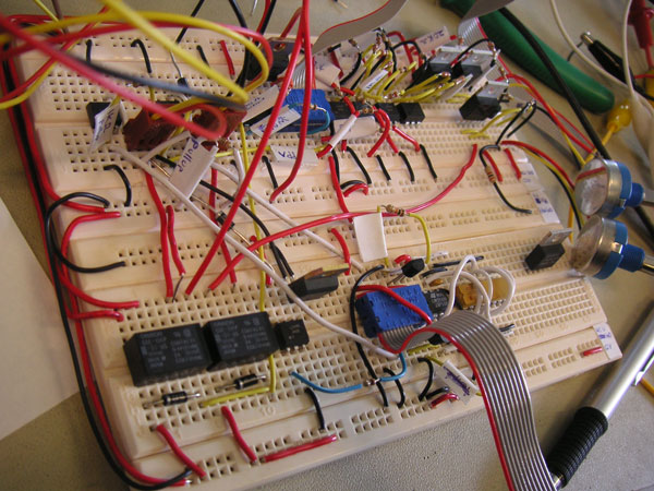
Temperature monitoring was pretty straightforward as it was already accomplished in Lab 5. However, we are now monitoring 2 temperatures, and hence require twice as much hardware. We chose the LM358 dual opamp as it was in our possession beforehand, and hence was free. More importantly, it was a dual opamp in a DIP-8 package, hence saving us valuable breadboard estate, which as you can see in the above diagram, was large. A gain of 3 was used in both sensors with a 10K resistor dip pack, to raise the voltage output of the LM34 sensors to a higher level. Both sensors were calibrated in software.
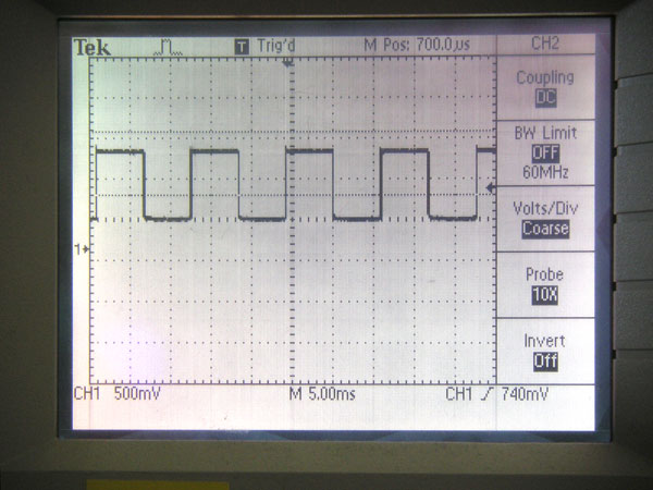
We supported fan speed monitoring via the tachometer output from standard 3-pin PC case fans. Research was done on what the signal looked like. Contrary to initial speculation, the output isn't a voltage corresponding to fan speed, but rather a pulse of varying period, created by the hall effect sensor within the fan. A 1Kohm pullup resistor to 12V was used to produce a nice clean square wave that is fed into the emitter side of an optoisolator. A 1Kohm resistor was chosen to provide enough current (12V/1000ohm = 12mA) to drive the emitter side of the optoisolator, while keeping the current low enough not to damage the fan tachometer circuit. The collector of the detector side is pulled up to 5V with a resistor in series, and the emitter is fed into the MCU port pin and translated to a fan speed by software.
Temperature is controlled by regulating the fan speed of the fan. In user mode, the user has control over the speed of the fan via 2 trimpots (right side of Fig. 1) that directly adjusts the fan supply voltage from ~7-12V. In autonomous mode, Fan 1 is controlled by voltage regulation with a 4-bit R-2R DAC that is optoisolated from the fan motors. An enable pin switches the fan on/off with a TIP31A NPN transistor. When the fan is on, a 4-bit binary value is specified by the MCU with 4 port pins. This value is then converted to a 0-12V voltage by the DAC, with 16 discrete voltages in between. It is then compressed to the 7-12V range with a resistor divider network, and then current boosted with an emitter-follower circuit. The emitter-follower circuit includes a low power 2N3904 NPN transistor and a high power TIP32C PNP transistor. A 0.7V voltage drop is incurred, but this is a design choice. A low-dropout adjustable voltage regulator could have been used instead, but this would cost more at the benefit of losing only 200mV. The fan 2 circuit is identical to fan 1, except the DAC is removed (auto mode is now connected directly to +12V) and the enable bit is now the PWM signal. The circuit is protected against reverse current spikes of the the motors of the 2 fans with a diode. In addition, the MCU is optoisolated from the fan circuit.
A Venable bit was used on the DAC/PWM voltage sources to turn on/off the fans. In the PWM mode, this bit is also used as the PWM signal. It is implemented with a TIP31A transistor acting as a switch, and the signal is optoisolated. A 1K resistor was chosen to provide sufficient current to the optoisolator while not drawing too much current from the prototype. While the original 300ohm resistor worked for the STK-500, the protoboard is apparently unable to support the current draw of the combined output pins.
Switching between user and auto modes is done with a 12VDC SPDT relay that has a 3A current rating. During the design phase, we explored the use of analog multiplexers, reed relays, high current SPDT IC switches, but ultimately decided to use electromechanical switches as only they had a high enough current rating to support normal DC fans and was economical. The downsides are the slight size increase, the soft clicking sound when a switch occurs, the low switching speeds and the fact that it contains moving parts. None of these are issues for our application though. Since the relay is a motor, it creates a negative current spike on a switch. We placed a diode in parallel with the relay coil to guard against this, as well as optoisolate it from the output port pin.
Switching between wireless mode and HyperTerminal mode is required since both make use of the serial port. It is an inherent design limitation with using the serial port of the MCU, but one that doesn't pose a huge problem. A MAX4053 triple 2:1 analog multiplexer was used to switch between the 2 inputs. The MUX was chosen as it supports both analog low voltage signals as well as CMOS/TTL level signals, and had 3 MUXes for redundancy. The select bit is physically connected to toggle switch that toggles between the 2 modes.
Switching between on and off (or high and low for PWM) for the auto mode is done with a TIP31A NPN transistor as it was free, has a high enough current rating and worked well. A slight voltage drop from 12V is incurred, but this isn't a big problem in our application.
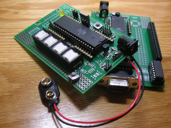
To stay within budget, we opted to use 2 protoboards instead of the STK-500 development board. Testing was done on the STK-500 and then verified on the actual protoboards. Extra hardware such as the DIP sockets and power sockets were soldered on even though they were not needed in the final design. This was done to aid in debugging, for redundancy and "just in case", as the soldering stations were often packed. In the final design, the main unit is powered off a computer power supply unit (PSU) and the remote control unit is powered by a 9V battery.
The remote control unit has 5 buttons that send data to the main control unit in order to control it. Four of these buttons control the threshold temperatures for the 2 fans(up/down), and the 5th switches between user and auto mode. All 5 are connected to port pins of the remote MCU.
We used the Radiotronix RCR-433-RP receiver and RCT-433-AS transmitter. The receiver is soldered onto the main unit protoboard, and the datasheet pinouts were connected to the relevant signals. A 0.1uf capacitor was put between Vcc and GND so as to reduce power supply noise. An 18cm antenna was used as it's 1/8 the wavelength of the signal The antenna is decoupled with a 100pf capacitor according to the spec sheet. The additional resistor/inductor RF choke was not connected due to space limitations. The resulting setup worked satisfactorily for our application even without them. The transmitter unit was mounted on the protoboard of the remote control unit. A 0.1uf surface mount capacitor was also placed between Vcc and GND. A similar antenna is used. Vcc was set to be 5V, which provided sufficient signal strength for the required range.
