The entire system consists of 2 units - the main control unit and the remote control. The high level block diagrams are shown below:

As the above block diagram shows, the main unit utilizes several of the MCU features learnt in class, including the I/O port pins, RS232 serial connection, the ADC(internal, not shown), LCD display, LED output, piezo speaker output and PWM output with varying duty cycle. In addition, a 4-bit R-2R DAC was built to control fan 1 via linear voltage regulation from 7-12V, and several switches were used to switch between inputs. For the switch between HyperTerminal and the RF receiver, we used a MAXIM MAX4053 triple analog mux to handle logic level signals, and for the switch between autonomous and user mode, we used two OMRON GE6 SPDT electromechanical relays to handle high current, +12V voltage sources.
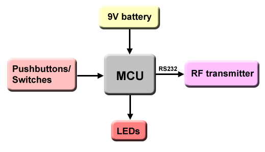
The remote control is relatively simpler than the main control unit. It simply has an MCU on a protoboard, a RF transmitter into the RS232 port to wireless transmission of user input, buttons for user input, and LEDs for status display.
