hardware design
Kasubana consists of four parts: the flower body, the motor, the E-field sensing unit, and the MCU. Each of them were implemented and tested separately prior to integration.
flower body
The flower body houses five actuation joints that connect the five petals to the main stem with five nitinol wires. Fig.2 shows the flower anatomy. When current is passed through the nitinol wires, the wires contract and straighten out, pushing the pedals downward. Thus, the flower opens.
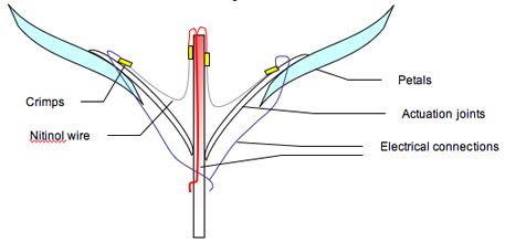
Fig.2 Flower anatomy
materials
The flower body was constructed with the following materials:
5 clear plastic tubes, 6cm each (ID = 2mm, OD = 4mm)
1 clear plastic tube, 13 cm, 5 lumen (ID = 3mm, OD = 6mm)
5 nitinol wires, 7cm each (diameter = 100 mm)
Connection wires
Thin metal wires (diameter = 0.15mm)
1 Thin brass sheet
1 Teflon tube
Shiny and nice origami paper
Super glue
Tape
actuation unit
To enable the flower to open its petals in a lifelike manner, we used nitinol, a shape memory alloy as our actuators. When heated, nitinol contracts and returns to its original shape, thus acting like a muscle. Because current must flow through the nitinol wires to heat it, a solid connection is essential. We crimped the two ends of a nitinol wire with electrical wire using a brass metal ring as shown in Fig.3.
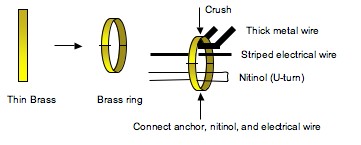
Fig.3 Connecting nitinol and electrical wire via crimp
Actuation joints were built with clear plastic tubes and crimped nitinol wires were added. Completed actuation joints were stuck onto a larger plastic tube acting as the flower stem .Petals were crafted using origami paper and stuck onto the joints. Fig. 4 shows a side and front view of the flower stem and actuation joints.
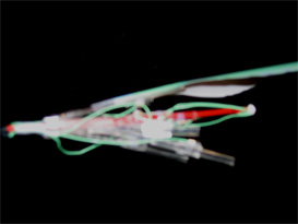 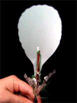
Fig.4 Flower construction
current source
Nitinol only contracts at high temperatures and thus a large amount of current is required. Fig. 5 shows the circuit used to supply current to heat the nitinol wires. The activation of the transistor was regulated by the MCU and the voltage supplied was pulse-width modulated to reduce the average current flow. The current source was separated from the MCU by an opto-isolator as a safety measure and also to reduce noise that could potentially affect the electrodes. A heat sink was attached to the transistor to prevent it from overheating.
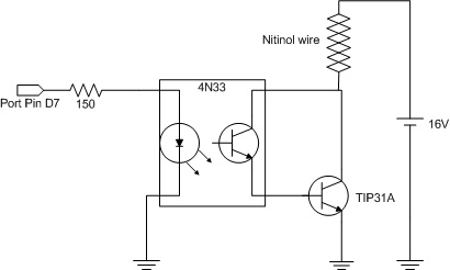
Fig. 5 Current source schematic
proximity detection unit
To detect human presence, we used the MC 33794 electric field imaging device (Motorola). Seven field electrodes were constructed using tin sheets and placed in a row. The electrode array was connected to the E-field sensor by coaxial cables and were shielded. Two reference capacitors (10 and 100 pF) were used as reference connections to reduce background noise. Fig. 6 shows the connection diagram for the MC 33794. The selector inputs were controlled by the MCU and the signal voltage on the electrode was sent to the analog-to-digital converter (ADC) in the MCU.
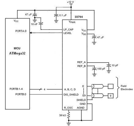
Fig. 6 E-field sensor schematic
motor unit
A two phase, bipolar stepper motor (8.4VDC, 30 ohm, 0.9 deg) from Applied Motion Products, Inc was used to rotate the flower. Bipolar motors require more complex driver circuitry but we chose to use it because it had a total of 400 half steps which allowed for a more precise orientation of the flower. Since two H-bridges are needed to drive the motor, we used an L239D (SGS-Thomson Microelectronics) push-pull four channel driver with diodes to drive it. Fig. 7 shows the schematic of the motor control unit.
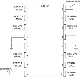
Fig. 7 Motor control unit
microcontroller
The ATmega32 (Atmel) was used to provide overall operation and control of the flower. The output of the E-field sensor was taken in by the ADC of the MCU while several port pins provided the signals to control motor rotation, turned on/off the current source needed for nitinol actuation. During the development and testing stages, the MCU also provided serial communication to a PC to obtain the readings of the E-field sensor. The MCU was mounted onto a PCB designed by Catherine Kung (Fig. 8) for another project (see Electric field animal presence detector).
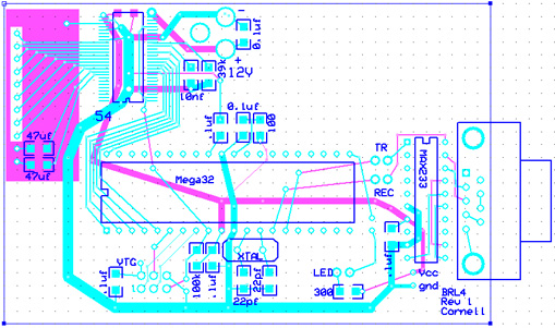
Fig. 8 Custom PC Board
other methods/features that didn't work
In the process of developing the final version of Kasubana, we tried various methods and wanted to add different features that didn't work in the end. Some failures were due to technical difficulties while others were due to time-constraints.
Initially, metallic actuation joints were used but soon discarded because they were too heavy and strong for nitinol to actuate. Another problem was with this design was that nitinol only contracted very slightly, thus the opening of the flower petals were not obvious.
One of the features we wanted to have was to enable the flower to bend in different directions. This was possible using a nitinol-embedded stem, however the required current was too high to supply and a stem that was too flexible would not be able to support the flower head.
Before designing an array of field electrodes, we tried using brass sheets to shape the flower petals and also act as electrodes for capacitance sensing. However, due to the fact that the orientation of the electrodes were constantly changing as the flower rotated, it was too difficult to calculate the base readings of the electrodes.
Developed by Ming-Zher Poh & Yuk Kee Cheung, © 2005 |