High Level Design:
Rationale and Sources for project idea:
We came across the idea for a digital thermometer because Matt had had some experience with a product that Brookstone, a specialty tools and electronics store, manufactures and sells. The product is called the “Grill Alert TM Talking Remote Thermometer” and is listed on their site for $75. We thought that it is an interesting idea to have a wireless thermometer so that one doesn’t have to stay standing at the grill while their meat cooks. In addition, we thought it would be a challenge to recreate Brookstone’s product with commonly available and cheap parts – the ATMega32 microcontroller, Radiotronix RF chips, a generic thermistor probe, a 4x20 line LCD, and a LM386 audio amplifier.
Background Math:
The only component that involved extensive math of our own in this project was the temperature probe. Other components such as the DPCM used for speech, error control coding for RF transmission, and fixed point techniques for various calculations in our software design are covered in their respective sections of the ECE 476 website.
The most significant calculations were for empirically finding a relationship between the temperature probe resistances as a function of temperature. Since this relationship is highly nonlinear, we had to choose a range of temperatures that would fit within a relatively linear range. According to an article found in Sensors magazine, “ You can obtain a more-or-less linear output voltage from a Wheatstone bridge/thermistor combination over a 40°–50°C range.” From studying the USDA recommended cooking temperatures that of our selected types of meat, we chose this range to be 106 to 210 °F. The general schematic for this Wheatstone bridge is pictured in Figure 5. As per the article’s recommendation, the bridge resistance (R in Figure 5) was chosen to be the thermistor’s resistance in the middle of the cooking range. This value was found to be approximately 2.2kΩ.
Next, we performed an experiment in the kitchen of Phillips hall to derive a relationship between the thermistor’s resistance, the voltage of the Wheatstone bridge, and temperature. In addition, this experiment verified our design choices mentioned previously. This experiment required holding both a commercial temperature probe and the thermistor in a pot of water that we slowly heated on a stove (Figures 6 and 7). We took measurements of the resistance (R T in Figure 5) across the thermistor and voltage (V out in Figure 5) of the Wheatstone bridge for every five degree change in water temperature. Our exact experimental circuit is pictured in Figure 8. VBIAS was set as 5 volts in anticipation of this circuit’s use on our transmitter protoboard. Using Excel we then plotted the findings of our experiment, and extracted regression lines from the data. Figure 9 shows the voltage of the Wheatstone bridge vs. temperature of the boiling water, while Figure 10 demonstrates the resistance of the thermistor vs. temperature. Note in Figure 10 the relatively linear range of resistance from 110 to 210 degrees. In addition, the equation for the linear regression of Figure 9 was ultimately used in our software design. Note that in Figure 9 that the voltage of the circuit was not measured for lower temperatures. To further improve the accuracy of our device, we could have plotted the voltage for these temperatures and made the equation in our microcontroller piecewise.
Math was also used to calculate the percentage the level of doneness of the meat. We played around with several equations implemented with fixed point math in our software. In the first equation, the doneness percentage is calculated to be :

However, this equation increased the percentage too slowly at low cooking temperatures and too wildly as current temperature approached the desired temperature. Thus, we ended up using the simpler equation:

Although this equation starts the percentage high (around 40% depending on the type of meat being cooked), we believe it provides a more accurate representation of “doneness” to the user.
To implement speech we used the AT&T text to speech demo to acquire the actual speech. We then downsampled and compressed the speech using the instructions and programs on Bruce Land’s speech compression page. All math and coded techniques are discussed on site as well.
Logical Structure:
The logical structure of our design consisted of two main components – the transmitter base station with temperature probe and the receiver with LCD and speech feedback. The base station takes in voltage measurements from the Wheatstone bridge circuit described above. These voltage measurements are converted into a temperature value through the ATMega32’s analog to digital converter. This temperature is then inserted into the payload of a data packet. These data packets are fully described in Meghan Desai and Yiling Li’s Wireless Telemetry project from ECE 476 in Spring ’05. These packets were then transmitted every second with the Radiotronix RCT-433 chip using Meghan Desai’s transmission driver. A logical overview of this system is pictured in Figure 11
The receiver’s logical structure is far more complex than the transmitter. This is largely because the receiver must both parse the incoming RF data into a temperature measurement while simultaneously outputting text information to a LCD and speech via Differential Pulse Code Modulation (DPCM). A single timer interrupt in the ATMega32 microcontroller directs the output of information to either an LCD or pulse width modulator. In addition, a press of any of the four pushbuttons attached to the unit changes the information displayed or speech output at any time. The logical structure of the receiver is displayed in Figure 12. The timing and hardware used to achieve these outputs are further described in the sections entitled “Hardware Design” and “Software Design” below.
Hardware/Software Tradeoffs:
Most of the components of our griller system had clearly defined roles in either in software or hardware so we did not really need to decide where to implement them. The wireless receive and transmit functionality was implemented in both hardware and software, but since we were using Meghan and Yiling’s driver we did not really have to worry about any compromises. The only part that needed some thought was the temperature probe. Because the probe’s resistance varies non-linearly with temperature, we could have chosen to interpret the resistance into a temperature completely in the Mega32. However, we feel that the cost in time and effort would not have been worthwhile, especially with such readily available information about Wheatstone bridge applications. The Wheatstone bridge makes the change in voltage across the thermistor linear as a function of temperature. This allows for the interpretation of the temperature much easier. Using hardware to simplify the software complexity helped out greatly in this instance, but over all we did not really have the need to strike a balance between the two.
Another large hardware tradeoff we had to make was the choice to use the smaller 4x20 LCD display as compared to the large 256 x 128 graphical display that we ordered from AllElectronics. Although we originally embraced the challenge of writing to this large LCD, we realized after about a week that we would not finish the project in time if we did not move on in the design of our project. However, this choice did not come without positives. For example, the power supply of the graphical display required a regulated -24 volt power source. This would have added on significantly to the area of our protoboard design, and could have ultimately made our receiver too large to be portable. In addition, the graphical display required a significant amount of time in order to write pixels over its entire area. This might have been impossible to accomplish in real time alongside speech and RF reception, whereas the 4x20 LCD was much more manageable to use in practice.
In addition, we would have liked to implement the full set of digits from 0 to 200 in the speech feedback of the Grillzilla for time and temperature. This would have required the following words and phonemes:
| One |
Eleven |
| Two |
Twelve |
| Three |
Thir |
| Four |
Fiff |
| Five |
Teen |
| Six |
Twen |
| Seven |
Hundred |
| Eight |
And |
| Nine |
|
| Ten |
|
However, the inclusion of these words and phonemes would have not left us room for phrases such as “Your meat is almost done!” in the flash memory. In addition, we calculated that we would not be able to fetch information from EEPROM in time enough for the ATMega32 to modulate the PWM signal to create recognizable speech. Thus, we ultimately decided that the Grillzilla would utter full phrases rather than the complete set of numbers. Perhaps another algorithm for implementing speech in the ATMega32 other than DPCM would have been useful, but this was not within the scope of our original design goals.
Finally, one trade off that we made in the software for the transmitter was for the equation used to convert the voltage measurement from the Wheatstone bridge into a temperature value. Matt first designed a fast algorithm without any floating point variables involved. The granularity of the temperature value resulting from this algorithm was too large, however – on the order of 5-7 degrees. Thus, Matt designed another algorithm.
Relationship of our design to industry standards:
Because we transmit information wirelessly on the 433 Mhz band, we have to follow the Section 15 FCC standards of transmission for low-power non-licensed transmitters. Accordingly, we refer to the document “Understanding the FCC Regulations of Low-Power Non-Licensed Transmitters” as well as parts of the full Section 15 protocol. Because our device is unlicensed it does not interfere with devices that run on different bands. In addition, it is able to take interference from other RF transmissions without great malfunction – i.e. if a packet is not received, the Grillzilla does not accidentally tell you that your meat is ready for consumption. In addition, we followed the USDA guidelines for the proper cooking of various meats, as well as suggested guidelines from professional cooking sources at the Cornell Hotel School. Figure 13 below shows the suggested temperatures from the USDA that we used.
Intellectual Property Considerations
Surprisingly, there are very little patent considerations in the Grillzilla. The Radiotronix RCR-433 and RCT-433 components are patent pending, so if we wanted to manufacture our device commercially we would eventually have to license the use of these chips. We are sure that the ATMega32 has patents on it as well, but we could not any through research. The LM386 doesn’t have any patents associated with it as well. Most importantly, Brookstone’s Grill Alert product doesn’t have any patents associated with it. Finally, we acknowledge Meghan Desai, Yiling Lee, and Bruce Land for all of the intellectual property in their code that we incorporated into our project.
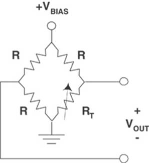
Figure 5: Wheatstone bridge used to linearize the thermistor probe’s response in voltage form.
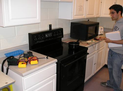
Figure 6: Setting up our experiment in the ECE kitchen
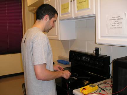
Figure 7: Jeff holding the digital temperature probe and the thermistor in a pot of boiling water in the ECE kitchen. This required most of Jeff’s AFROTC acquired strength, as he had to do this for about forty minutes.
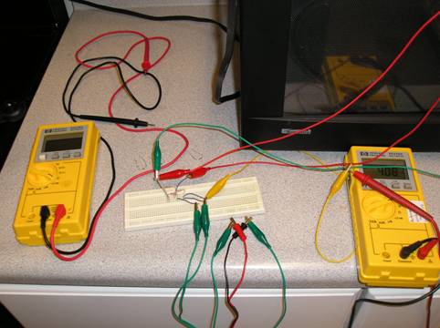
Figure 8: Experimental setup of Wheatstone bridge and thermistor
Figure 11: Logical structure of transmitter base station
Figure 12: Logical structure of receiver
|
Beef |
Veal |
Lamb |
Pork |
Poultry |
Fish |
Medium Rare |
145 |
145 |
145 |
160 |
170 |
145 |
Medium |
160 |
160 |
160 |
160 |
170 |
155 |
Well Done |
170 |
170 |
170 |
170 |
180 |
160 |
Figure 13: USDA recommended cooking temperatures |