Program (Software) Details
The design of the software for the Grillzilla transmitter is relatively simple compared to the receiver. The A/D converter for the device is set to use AVCC on the ATMega32 as its voltage reference, and the result is set to be left adjusted. Thus, the equation for the A/D converter result in ADCH and ADCL is

This result is then used in our equation to determine the temperature, which is:
temperature = fix2int(float2fix(-2.16577695*ADCH + 560));
The fix2int and float2fix functions are from Bruce Land’s fixed point math page, which the specific coefficients in the equation result from inverting the regression equation derived from the data in Figure 9.
Every second ADCH is retrieved and run through the equation for the temperature, and the value that results is fed into the payload of a data packet. This information is padded with the appropriate packet data using the generate_data() function, and then transmitted. Another A/D reading is then requested, and the microcontroller waits another second for the process to repeat. Note that a packet count is sent in the payload of the packet as well. This information is used in the receiver to determine if data packets have been lost, which ultimately determines whether the temperature data is valid and should be incorporated into the user feedback.
The software for the receiver is more complicated due to the wide array of inputs and outputs of the program. The simplest input to the receiver program is pushbuttons. These are connected to Port A and debounced every 125 ms by the program’s state machine. The state machine’s four conditions determine whether the button has been pressed or not, and resemble the state machines we used in all of the in-class labs this semester (see Figure 14).
In addition to the state machine for the pushbuttons, there is one that determines which menu of the Grillzilla is displayed. Figure 15 shows this state machine in full detail. When the unit is first turned on, a welcome screen is displayed. After a short delay, the main menu of the screen is displayed (Figure 16). In this menu, pushbuttons 1 and 2 change which of the three menu lines of the screen is selected. This selection is indicated by an arrow in front of the selected line on the left hand side of the screen (see Figure 16). When pushbutton 3 is pressed, the selected meat, preparation, or timing mode is cycled. This selection is reflected in the selectedMeat, selectedPrep, and timerMode variables, and determines what information is displayed on the next screen.
When pushbutton 4 is pressed in the main menu, one of two things happen. If self timer mode is set to yes, the receiver proceeds to display the timer menu. However, if timer mode is not selected the grilling screen is displayed. Figure 17 shows the timer menu screen. In this menu, pushbuttons 1 and 2 move the blinking cursor on each digit of the time left and right. This display corresponds to the variable of the time that will be modified when pushbutton 3 is pressed. After the user has selected how long they would like to grill, a single press of pushbutton 4 displays the grilling menu screen.
The grilling menu screen comes in two flavors depending on whether the timer mode is selected or not. In either case, once the receiver unit enters this state the RF receiver is enabled and the incoming temperature data is immediately recorded. Figure 18 shows the version of the grilling screen that is displayed when timer mode is disabled. On this screen the desired temperature is displayed according to which meat and preparation the user selected in the main menu. In addition, the current temperature is displayed according to the incoming RF data. When a dropped packet is detected by the software, the current temperature displays the phrase “NoRange”. In addition to the current and desired temperatures, the percent that the meat is done is displayed. This piece of the program was especially tricky to write, as fixed point math had to be smartly exploited so that the display of the LCD and reception of RF data was not adversely effected.
If the timer mode is selected, a version of the grilling screen depicted in Figure 19 is shown. The time in this screen is count down until it reaches 0: 00:00, in which case the phrase “Expired” appears under the phrase “Time:”. Note that in both Figures 18 and 19 that the packet number is displayed as debugging information in the top right corner of the screen.
Note that in the main and timer menus, the LCD is refreshed only if a button is pressed. This occurs through the use of four LCD buffers and the functions menuPrint() and timerPrint(). These functions modify the LCD buffer strings depending on a multitude of variables that are effected by the user’s button presses. At the end of the execution of each of these functions, LCDPrint() is called. This function takes the LCD buffer strings, clears each line of the LCD screen, and sends each string to the correct line.
Throughout program execution, there is the possibility of voice feedback. For example, when the unit is turned on it exclaims “Grillzilla”! In addition, when the current temperature almost reaches the desired temperature, the device says “Your meat is almost done”. Also, when the current temperature reaches the desired temperature the device says “Your meat is done!”. Finally, when button 3 is pressed on the grilling menu screen the device says “Your meat is not done”.
This speech was implemented through DPCM via the PWM output of the ATMega32 as mentioned earlier in this report as well as used extensively lab 2 of the class. The speech was especially hard to incorporate into the design of the receiver’s software, as it must take priority over the state machines and LCD display to function properly. Thus, the time base for the state machines and cooking timer as well as the speech output functionality was implemented in a single ISR (Timer 0 Overflow). In addition, Boolean flags were used extensively to lock out the processing of RF data, triggering of the state machine, counting down the cooking timer, and calling any LCD print function while speech was initialized or in progress. Overall, the design of the code for the Grillzilla receiver is not particularly complex with respect to data structures or algorithms used. However, the integration of the various input and output sources as well as careful detail to the menu displays provided a significant programming challenge. There wasn’t any attempted part of the software that didn’t eventually work without all of the using debugging and careful layout. See the appendix for our commented code.
Referenced Code:
Bruce Lands’s fixed point math routines: macros and optimized multiply
Bruce Land’s DPCM coding techniques: MATLAB programs here and here, and test program here
Meghan Desai’s RF transmission and reception programs: rx.c, tx.c, and txrx.c
Codevision’s LCD driver
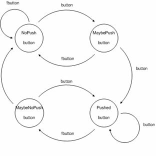
Figure 14: State machine for pushbuttons on receiver unit
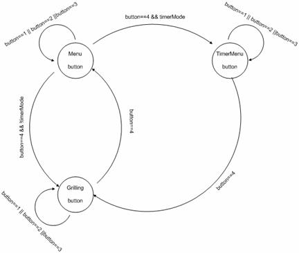
Figure 15: State machine for menus on receiver unit
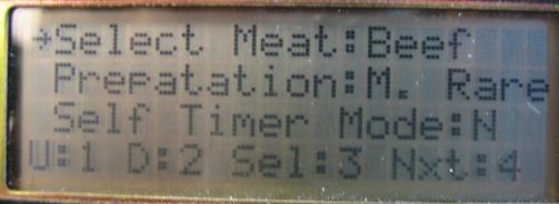
Figure 16: Main menu of Grillzilla receiver unit
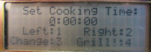
Figure 17: Timer menu screen of Grillzilla receiver unit
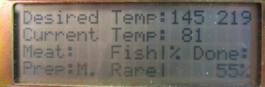
Figure 18: Grilling menu screen of Grillzilla receiver unit (timer mode disabled)
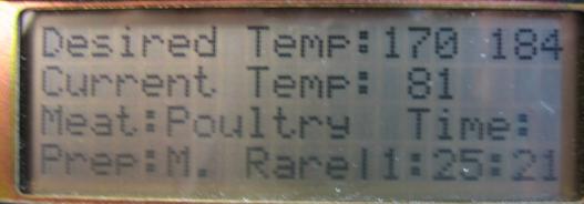
Figure 19: Grilling menu screen of Grillzilla receiver unit (timer mode enabled) |