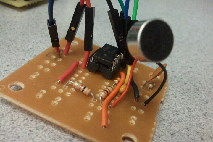
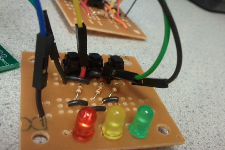
Our hardware setup consists of a prototype board that hosts the MCU and three other individual function panels. Audio input is processed through the amplifier panel and sampled by the MCU. The RS232 board allows the state of the MCU and user input to be sent to the PuTTY. The last function panel allows user to change the current operating mode of the MCU and enables the audio input to be sampled or discarded in the main program.
A Smart Voice Decoder System for Vowels
By: Annie (Wei) Dai (wd65@cornell.edu) and Youchun Zhang (yz526@cornell.edu)

Hardware Design
Overview
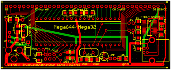
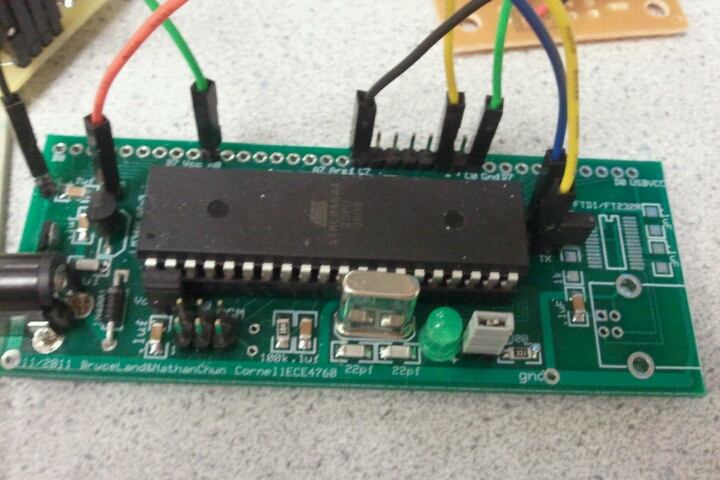
ECE 4760 Custom PCB
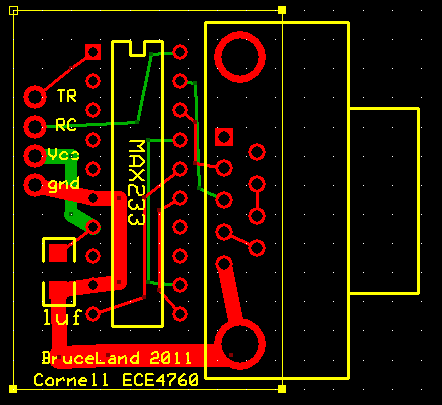
The prototype board we used is the mega644 prototype board design by Bruce Land. The printed PCB layout is shown below. The only port pins used (soldered) are C0,C1,C7 and A0. We also had to solder RX and TX pins to enable RS232 serial communication.
Audio Amplifier Circuit Panel

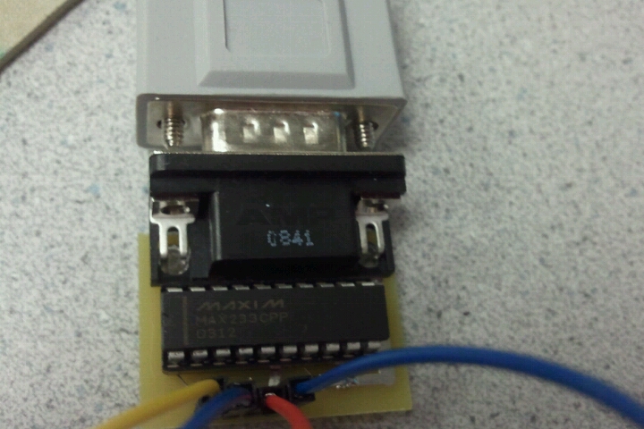
RS232 Serial Communciation Panel
To better user experience with our design, we decided to use serial communication via PuTTY to inform the user of the current operating state of the program. We also felt that it would be a lot more convenient if the user could control the program via both hardware as well as software. To enable serial communication between the MCU and a PC, we used the Max233CPP level shifter chip and the RS232 connector PCB Bruce had designed. The transmit and receive pins on the MCU prototype board are connected to the TR and RC pins on the RS232 board to enable communication.
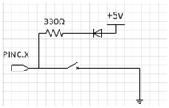
Hardware User Interface (Control Buttons)
Copyright ECE 4760 Spring 2011 Annie (Wei) Dai and Youchun Zhang
