Cornell University ECE4760
PLIB, C and Assembler considerations
PIC32MX250F128B
Introduction
Most of this material comes from the
MPLAB® XC32 C/C++ Compiler User’s Guide. Section numbers below refer to this document.
I chose to include topics here that I found to be useful or tricky to think about. Feel free to suggest additions.
Debugging
If your program just sits there and does nothing:
--
Did you turn on interrupts? The thread timer depends on an interrupt.
-- Did you write each thread to include at least one YIELD (or YIELD_UNTIL, or YIELD_TIME_msec) in the while(1) loop?
-- Did you schedule the threads?
-- Did you ask to initialize the TFT display in the code, while not having a TFT on the board?
-- Does the board have power?
If your program reboots about 5 times/sec:
--
Did you exit from any scheduled thread? This blows out the stack.
-- Did you turn on any interrupt source and fail to write an ISR for that source?
-- Did you divide by zero? A divide by zero is an untrapped exception.
-- Did you write to a non-existant memory location, perhaps by using a negative (or very large) array index
-- Did you use single quotes to define the FORMAT string in a PRINTF statment
.
If your thread state variables seem to change on their own:
--- Did you define any automatic local variable? Local variables in a thread should be static.
-- Are your global or static arrays big enough the clobber the stack in high memory?
You should be able to use max ~30 kbytes.
PLIB
- PLIB examples (and all the examples ZIPPED)
- Using PPS -- PIC32 Family Reference Manual section 12.3
- Using PPS -- In the MPLABX GUI, open HELP, then search PPS
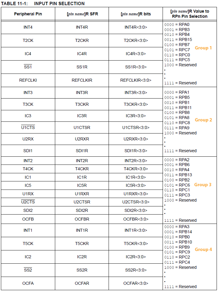
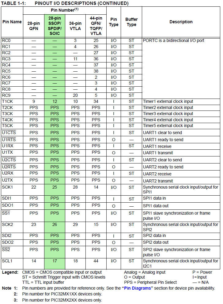
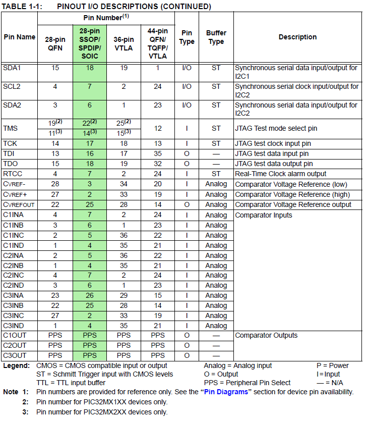
- Using PPS input-- PIC32MX250F128B Peripheral Pin Select (PPS) input table
-- example -- UART receive pin
specify PPS group, signal, logical pin name
PPSInput(2, U2RX, RPB11); //Assign U2RX to pin RPB11 -- Physical pin 22 on 28 PDIP
Note that the groups (1 to 4) are delimited by horzontal lines in the righthand column..
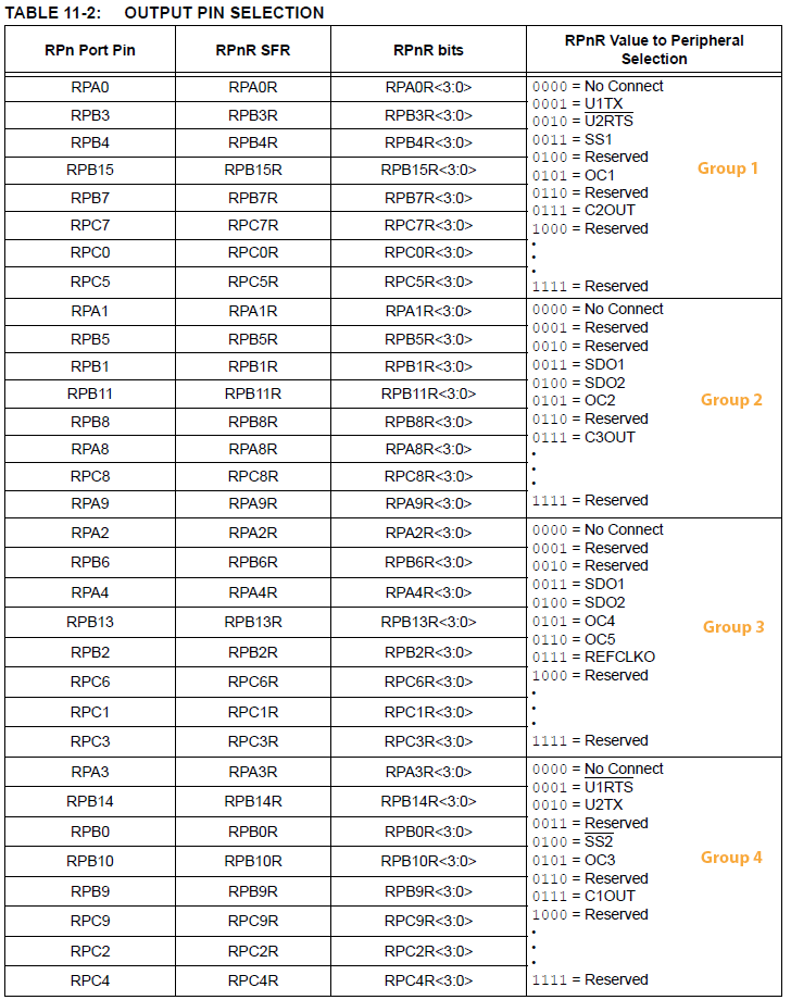
- Using PPS output -- PIC32MX250F128B Peripheral Pin Select (PPS) output table
-- example -- UART transmit pin
specify PPS group, logical pin name, signal
PPSOutput(4, RPB10, U2TX); //Assign U2TX to pin RPB10 -- Physical pin 21 on 28 PDIP
Note that the groups (1 to 4) are delimited by horzontal lines in the righthand column.
-- example -- set up compare 1
CMP1Open(CMP_ENABLE | CMP_OUTPUT_ENABLE | CMP1_NEG_INPUT_IVREF);

PPSOutput(4, RPB9, C1OUT); //pin18

mPORTBSetPinsDigitalIn(BIT_3); //Set port as input (pin 7 is RB3)
Note that PORTB/bit3 is NOT on PPS. It has a fixed pin location.
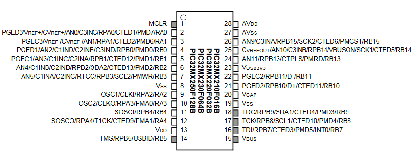
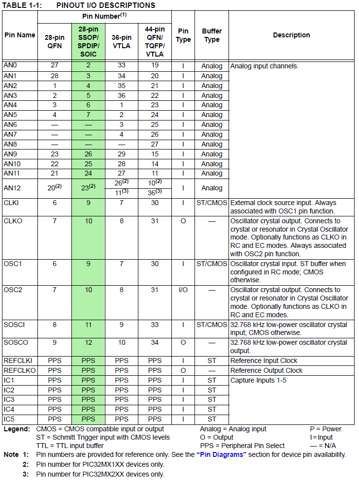
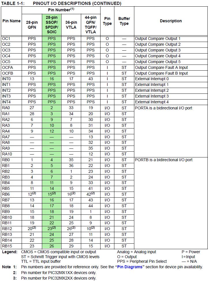
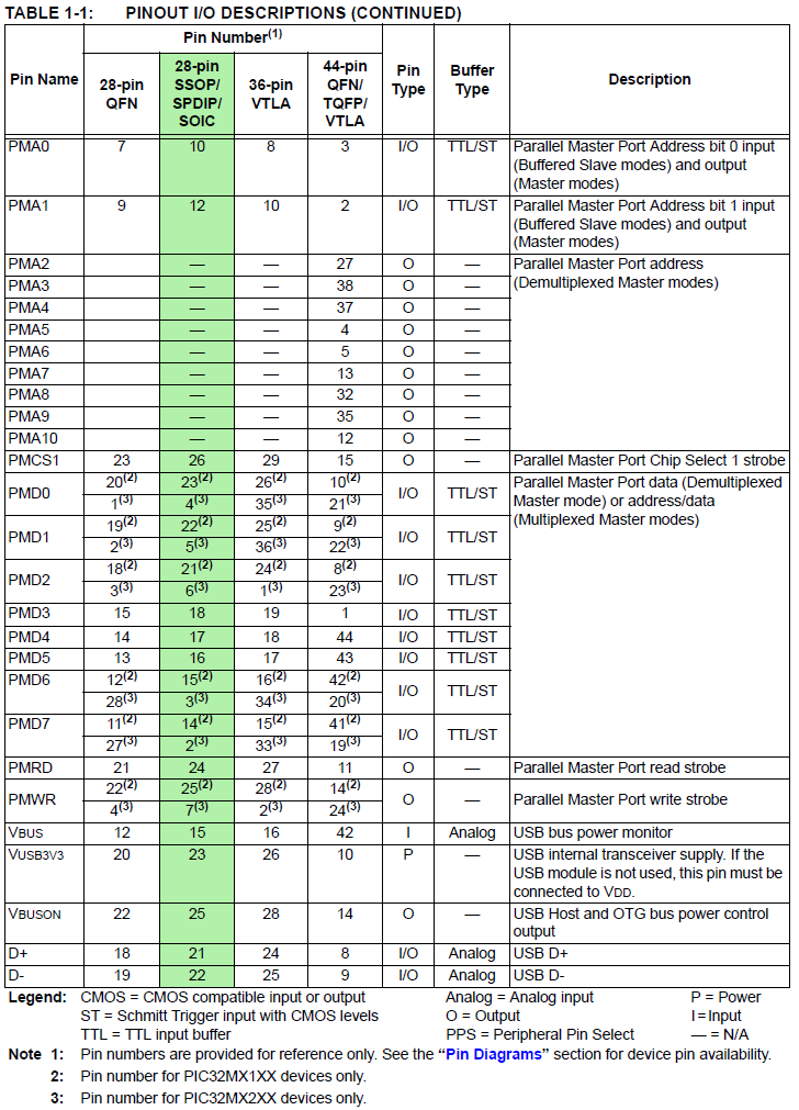
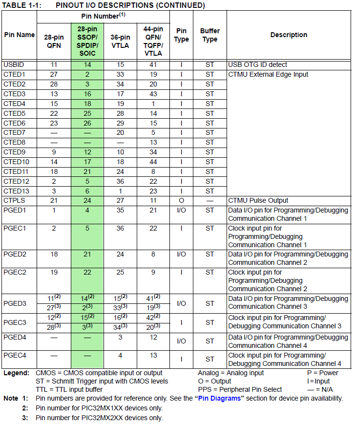
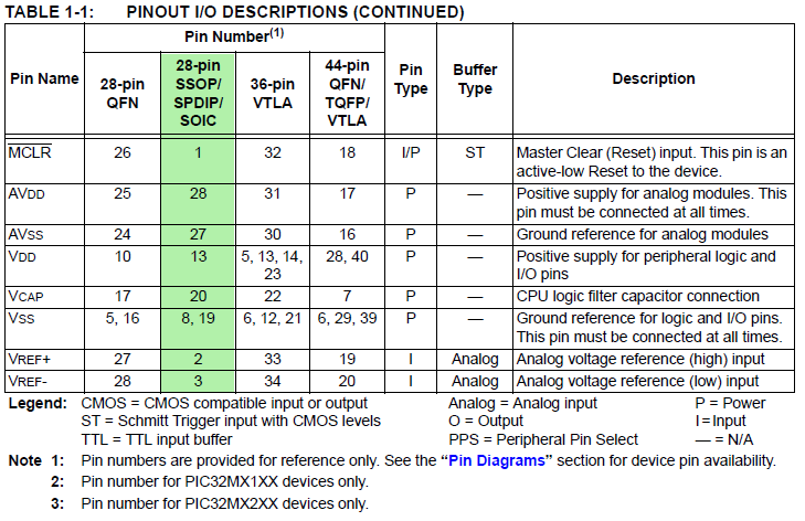
- PDIP pinout by pin for PIC32MX250F128B :::
Signal Names=>Pins ::: 1, 2, 3, 4, 5, 6, 7 PDIP highlighted in green (for PPS refer above)
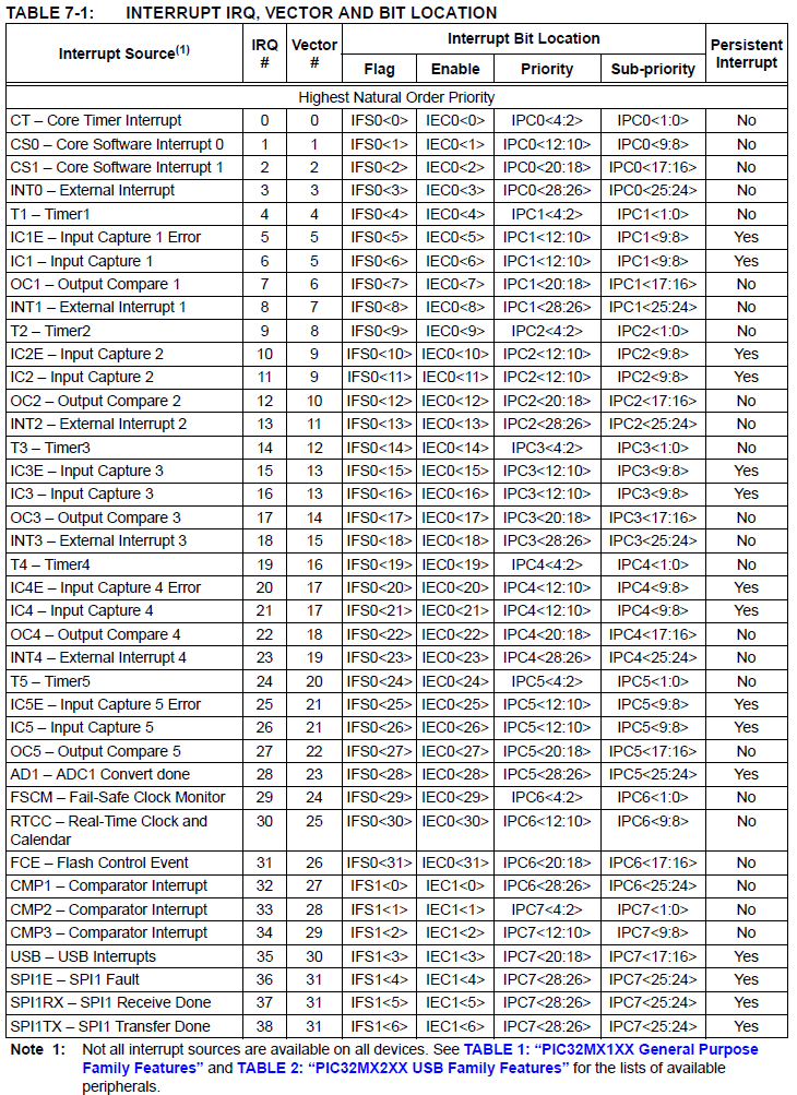
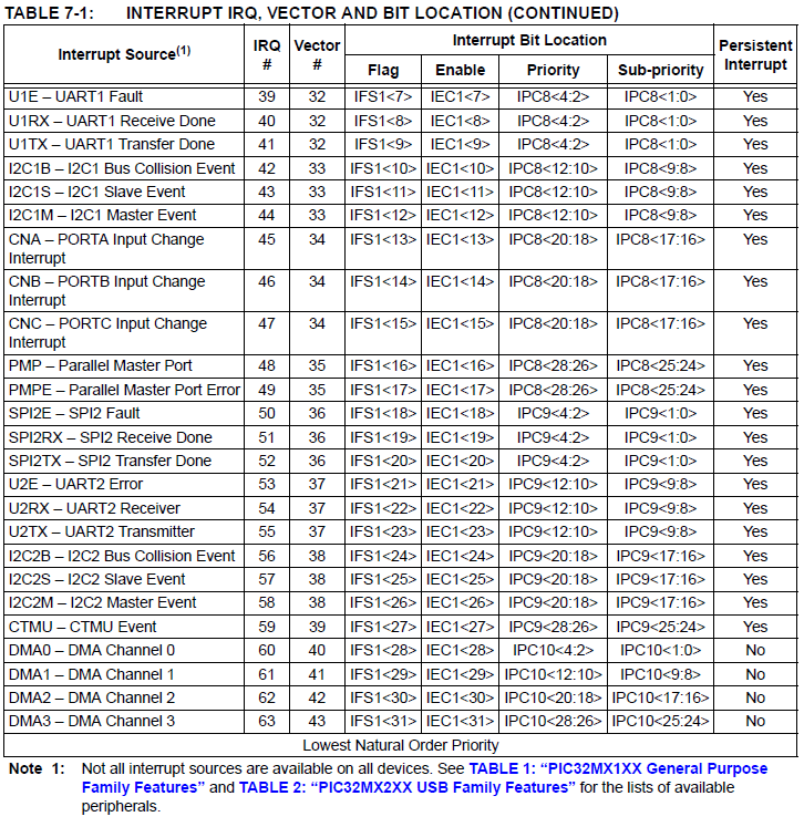
- Interrupt Table 1, 2 and int_1xx_2xx.h -- interrupt IRQ names and vector names
Stuff that should be in PLIB
I added a few items to the PLIB macros.
- Macros for pullup/pulldown resistors on i/o pins.
The poorly documented CNPDB register (Change Notice Pull-down Enable B) selects input bits to pull down.
See section 12.2.6 of the i/o reference manual.
For instance, setting:
CNPDB = BIT_7 | BIT_8 | BIT_9
pulls down B7, B8, and B9. To be safe, you should probably clear the CNPUB register to turn off pull up resistors.
If you include the following macros:
// PORT B

#define EnablePullDownB(bits) CNPUBCLR=bits; CNPDBSET=bits;

#define DisablePullDownB(bits) CNPDBCLR=bits;

#define EnablePullUpB(bits) CNPDBCLR=bits; CNPUBSET=bits;

#define DisablePullUpB(bits) CNPUBCLR=bits;

//PORT A

#define EnablePullDownA(bits) CNPUACLR=bits; CNPDASET=bits;

#define DisablePullDownA(bits) CNPDACLR=bits;

#define EnablePullUpA(bits) CNPDACLR=bits; CNPUASET=bits;

#define DisablePullUpA(bits) CNPUACLR=bits;
Then you can just write
EnablePullDownB( BIT_7 | BIT_8 | BIT_9);
There is support for pullup in PLIB
(ConfigCNPullups) but it is not organized by port bit number and there is
no support for pulldowns that I could find.
- Macros for using the charge/time measurment unit (CTMU)
It is nicer to define some macros to make the CTMU use easier. But note that this set is not complete.
I have not yet written macros for external triggering. These are sufficient for the examples on the CTMU page.
// hardware-available current levels
#define CTMUuA550 0 // 550 microamps
#define CTMUuA55 3 // 55 microamps
#define CTMUuA5point5 2 // 5.5 microamps
#define CTMUuApoint55 1 // 0.55 microamps
// turn on/off the current source
#define CTMUenable CTMUCONbits.ON = 1;
#define CTMUdisable CTMUCONbits.ON = 0;
// use one of the 4 current levels defined above for CTMUcurrentSet
#define CTMUcurrentSet(current) CTMUCONbits.IRNG=current;
// dissharge the cap under test, if necessary.
// shorts the current source to ground
#define CTMUdishargeON CTMUCONbits.IDISSEN=1; // I source grounded
#define CTMUdishargeOFF CTMUCONbits.IDISSEN=0;
// edge state 0/1 off/on
// to used to quickly gate the current source -- READ the MANUAL!
#define CTMUedge1State(binary) CTMUCONbits.EDG1STAT = binary;
#define CTMUedge2State(binary) CTMUCONbits.EDG2STAT = binary;
These definitions are used in a modified capacitance code.
Builtin Functions
Builtin functions seem to be part of the compiler and not another library. Most seem to be assembly language-like features. For instance, there are functions for DSP, wrappers for assembly language, and specialized stuff like reading COPROCESSOR 0 (CP0) registers. The XC32 manual has a list of MIPS builtin functions in Appendix D, but the list is not complete. Another XC32 manual Appendix D.2 has more. The online compiler help in XPLAB lists all of the DSP builtins (but be sure you are looking at XC32 and not XC16 compiler). The header xc.h (excerpt) lists more.
Coprocessor 0 is a MIPS hardware extension which handles low-level interrupt handling, trace control, and processor monitoring. The CPU manual section 2.12 has a list of coprocessor 0 registers. Access to coprocessor 0 registers is possible using the low level assembler opcodes MTC0 and MFC0. These two opcodes are packaged into builtins to use in C.
This example reads CPU cycles since start, but note that it overflows every 100 seconds or so:
// __builtin_mfc0(register_number,select_number)
unsigned int proc_count ;
proc_count = __builtin_mfc0(9,0); // processor cycle count is register 9
You can write a coprocessor 0 register (carefully) using
__builtin_mtc0(regster_number, select_number, value)
You might profile the execution time of an add statment in C with something like:
__builtin_mtc0(9,0,0); // zero the processor cycle count
for (i=1; i<=iter_count; i++) { sum += i ;}
proc_count2 = __builtin_mfc0(9,0); // processor cycle count
printf("cycles/loop=%u, sum=%f \r\n", (proc_count2)/iter_count, (float)sum);
There are a few other useful builtins. Two commands can give you the number of leading or trailing zeros on a number.
This can be useful for estimating log base-2, and generally for scaling numbers. The following sets b=16 and c=8.
a = 0x0000ff00;
// CLZ "count leading zeros"
b = __builtin_clz(a);
// CTZ "count trailing zeros"
c = __builtin_ctz(a);
The
Fixed point macros
Fixed point is considerably faster than floating point on the PIC32 architecture here are some fixed point schemes and examples.
Update: The compiler now supports fixed point types.
You probably will want to use the built-in types rather than the macros shown below.
- 16-bit integer with 16-bit fraction (16:16 format). Good all around choice for graphics and physics calculations.
Slow for digital filtering, but you can make very accurate filters. Example use.
Note that float2fix, fix2float, and sqrt are floating operations, and therefore slow.
// ===16:16 fixed point macros ========================================
typedef signed int fix16 ;
#define multfix16(a,b) ((fix16)(((( signed long long)(a))*(( signed long long)(b)))>>16)) //multiply two fixed 16:16
#define float2fix16(a) ((fix16)((a)*65536.0)) // 2^16
#define fix2float16(a) ((float)(a)/65536.0)
#define fix2int16(a) ((int)((a)>>16))
#define int2fix16(a) ((fix16)((a)<<16))
#define divfix16(a,b) ((fix16)((((signed long long)(a)<<16)/(b))))
#define sqrtfix16(a) (float2fix16(sqrt(fix2float16(a))))
#define absfix16(a) abs(a)
- 2-bit integer (sign bit and one bit) with 14-bit fraction (2:14 format). Good for fast, reasonable accuracy filters.
For more than 2-pole IIR, you must use Second-Order-Section filters (example 6 on DSP page).
// == bit fixed point 2.14 format ===============================
// == resolution 2^-14 = 6.1035e-5
// == dynamic range is +1.9999/-2.0
typedef signed short fix14 ;
#define multfix14(a,b) ((fix14)((((long)(a))*((long)(b)))>>14)) //multiply two fixed 2.14
#define float2fix14(a) ((fix14)((a)*16384.0)) // 2^14
#define fix2float14(a) ((float)(a)/16384.0)
#define absfix14(a) abs(a)
GCC XC32
- Device Header Files (Section 4.3)
There is one header file that is recommended be included into each source file you write. The file is <xc.h> and is a generic file that will include other device-specific header files when you build your project. Inclusion of this file will allow access to SFRs via special variables, as well as #defines which allow the use of conventional register names from within assembly language files.
- The Stack (Section 4.4)
The PIC32 devices use what is referred to in this user’s guide as a “software stack”. This is the typical stack arrangement employed by most computers and is ordinary data memory accessed by a push-and-pop type instruction and a stack pointer register. The PIC32 devices use a dedicated stack pointer register sp (register 29) for use as a software Stack Pointer. All processor stack operations, including function calls, interrupts and exceptions, use the software stack. It points to the next free location on the stack. The stack grows downward, towards lower memory addresses. By default, the size of the stack is 1024 bytes.The run-time stack grows downward from higher addresses to lower addresses. Two working registers are used to manage the stack:
• Register 29 (sp) – This is the Stack Pointer. It points to the next free location on the stack.
• Register 30 (fp) – This is the Frame Pointer. It points to the current function’s frame.
No stack overflow detection is supplied.
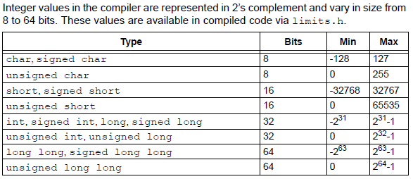
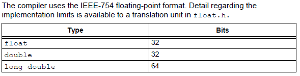
- Data Types (Chapter 6)
Types, their ranges, how to specify the types, and how structs, bit fields, and unions are defined.
The compiler stores multibyte values in little-endian format. That is, the Least Significant Byte is stored at the lowest address.
- Integer Promotion (Section 8.2)
Integral promotion is the implicit conversion of enumerated types, signed or unsigned varieties of char, short int or bit field types to either signed int or
unsigned int. If the result of the conversion can be represented by an signed int, then that is the destination type, otherwise the conversion is to unsigned int.
Consider the following example:
unsigned char count, a=0, b=50;

    if(a - b < 10)

    count++;
The unsigned char result of a - b is 206 (which is not less than 10), but both a and b are converted to signed int via integral promotion before the subtraction takes
place. The result of the subtraction with these data types is -50 (which is less than 10) and hence the body of the if() statement is executed. If the result of the subtraction is to be an unsigned quantity, then apply a cast.
For example:
if((unsigned int)(a - b) < 10)

    count++;
The comparison is then done using unsigned int, in this case, and the body of the if() would not be executed. Another problem that frequently occurs is with the bitwise compliment operator, ~. This operator toggles each bit within a value. Consider the following code:
unsigned char count, c;

  c = 0x55;

  if( ~c == 0xAA)

  count++;
If c contains the value 0x55, it often assumed that ~c will produce 0xAA, however the result is 0xFFFFFFAA and so the comparison in the above example would fail. The compiler may be able to issue a mismatched comparison error to this effect in some circumstances. Again, a cast could be used to change this behavior.
- Interrupt mechanism and syntax (Section 11.3. This section also has several ISR examples)
An interrupt function must be declared as type void and may not have parameters. This is the only function prototype that makes sense for an interrupt function since they are never directly called in the source code. Interrupt functions must not be called directly from C/C++ code (due to the different return instruction that is used), but they themselves may call other functions, both user-defined and library functions, but be aware that this may use additional registers (and therefore cycles) which will need to be saved and restored by the context switch code. A function is marked as an interrupt handler function (also known as an Interrupt Service Routine or ISR) via either the interrupt attribute or the interrupt pragma1. While each method is functionally equivalent to the other, the interrupt attribute is more commonly used and therefore the recommended method. The interrupt is specified as handling interrupts of a specific priority level or for operating in single vector mode.
- Preprocessor (Section 16)
Macro expansion using arguments can use the # character to convert an argument to a string, and the ## sequence to concatenate arguments. If two expressions are being concatenated, consider using two macros in case either expression requires substitution itself, so for example,
#define paste1(a,b) a##b

    #define paste(a,b) paste1(a,b)
lets you use the paste macro to concatenate two expressions that themselves may require further expansion. The replacement token is rescanned for more macro identifiers, but remember that once a particular macro identifier has been expanded, it will not be expanded again if it appears after concatenation. The type and conversion of numeric values in the preprocessor domain is the same as in the C domain. Preprocessor values do not have a type, but acquire one as soon as they are converted by the preprocessor. Expressions may overflow their allocated type in the same way that C expressions may overflow. Overflow may be avoided by using a constant suffix. For example, an L after the number indicates it should be interpreted as a long once converted.
So for example:
#define MAX 100000*100000

    and

    #define MAX 100000*100000L
(note the L suffix) will define the values 0x540be400 and 0x2540be400, respectively.
GCC general (Also see Common C errors)
-
Never ignore a warning!
This version of C will accept misspelled ISR names and nonexistant functions with just a warning, among other nasty surprises.
-
Use static, const and volatile variables correctly.
Incorrect use may affect program execution and efficiency. Every variable which is set in an interrupt and read in main (or vice-versa) must be declared as volatile. The optimizer may remove variables which change asynchronously in an ISR unless you use the volatile keyword.
-
Distinguish between = and ==.
When xyzzy is a variable, the following syntax using = instead of ==:
if (xyzzy=0){stuff};
is completely legal and will never enter the if-block because the variable is first assigned the value zero, then checked to see if it is not-zero.
-
The operators ! (logical not) and ~ (bitwise not) are not equivalent.
Let's say we have the char variable xyzzy=1. The syntax:
if (~xyzzy){stuff};
will always enter the if-block because ~1 for a char variable is 0xFE, which is non-zero.
-
The operators & (bitwise and) and && (logical and) are not equivalent.
Let's say that xyzzy=1 and abx=2.
Then (xyzzy & abx)=0 but (xyzzy && abx) = 1 (logical TRUE)
Similarly for | and || (bitwise and logical or).
-
Variables seem to change without reason.
If variables seem to be changing on their own, or inserting debug variables seems to 'fix' the problem, you probably have a memory issue. Check the compiler-generated .map file. Look for zero-based versus one-based array errors.
Look for buffer overruns! You can overrun array boundaries at run time (C has no bounds checks). This includes strings which are longer than the declared array size.
-
Watch out for the radix of constants.
When mixing binary and hex (0b, 0x) in assignments it is very easy to miss mistakes like
REGISTER=0x00001000; when you meant to use binary.
-
Buffer overrun errors are easy when printing or copying strings.
Use snprintf instead of sprintf to print a given number of characters.
There is also strncopy instead of strcopy as well as other number-limited string commands.
-
Putting a semicolon at the end of a for statement makes the statement a null loop!
for (i=0; i<10; i++); <--wrong (unless for some reason you want a null loop).
Assembler (see also MPLAB® XC32 ASSEMBLER, LINKER AND UTILITIES User’s Guide)
- Assembler Listing
To get a listing:
menu item Window>Debugging>output>Dissasembly
But note that
in Project Properties>Loading you need to check Load symbols when programming
- Mixing C and assembler (Section 14)
If assembly must be added, it is preferable to write this as self-contained routine in a separate assembly module rather than in-lining it in C code. I do sometimes write inline assembler, but keep it simple and short.
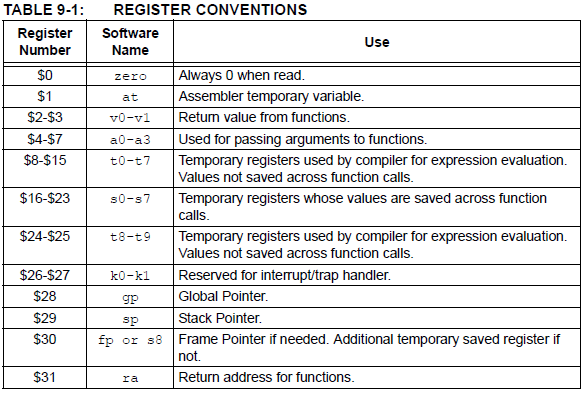
- Register Conventions (Section 9.3)
- Register Definitions (Section 4.5.1)
When the CP0 register definitions header file is included from an Assembly file,
the CP0 registers are defined as:
#define _CP0_register_name $register_number, select_number
For example, the IntCtl register is defined as:
#define _CP0_INTCTL $12, 1
- Interrupt context switch (Section 11.6)
The standard calling convention for C/C++ functions will already preserve zero, s0-s7, gp, sp, and fp. k0 and k1 are used by the compiler to access and preserve non-GPR context, but are always accessed atomically (i.e., in sequences with global interrupts disabled), so they need not be preserved actively. A handler function will actively preserve the a0-a3, t0-t9, v0, v1 and ra registers in addition to the standard registers. An interrupt handler function will also actively save and restore processor status registers that are utilized by the handler function. Specifically, the EPC, SR, hi and lo registers are preserved as context. Handler functions may use a shadow register set to preserve the General Purpose Registers, enabling lower latency entry into the application code of the handler function. On some devices, the shadow register set is assigned to an interrupt priority level (IPL) using the device Configuration bit settings (e.g., #pragma config FSRSSEL=PRIORITY_6). While on other devices, the shadow register set may be hard wired to IPL7.
See also:
PIC32 Architecture and Programming John Loomis
Copyright Cornell University
March 5, 2021