
Cornell University ECE4760
SPI Port Expander
MCP23s17
Introduction
The PIC32 in 28-pin PDIP has limited i/o ports. The MCP23s17 port expander adds two 8-bit i/o ports, at the cost of 4 pins on the PIC32.
Two more pins may be used, if you need the expander to generate interrupts.
PIC32 i/o pins used on big board for Port Expander
SPI chip select ports have jumpers to unplug.
----------------------------
RA2 port expander intZ
RA3 port expander intY
RA4
PortExpander SPI MISO
RB5 DAC/PortExpander SPI MOSI
RB9 Port Expander SPI chip select (can be disconnected/changed)
RB15 DAC/PortExpander SPI Sclock
----------------------------
Software for port expander on SECABB
--Current Protothreads version is 1_3_2.
See the Protothreads page for details on 1_3_2.
Download this ZIP file to get all the libraries and the project example in one place.
Specifically, it includes the header and code for the port expander.
You will be able to delete the test code from the project and then include the following code which forms the basis of lab 1.
DDS_Accum_Expander_BRL4.c for 2019 lab 1.
Read the description! (example 1 in the Sound page) also read the Keypad page
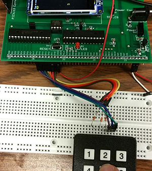
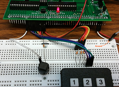
--Keypad using Port Expander The example code for lab 1 uses a environment which includes the port expander library (details below). This example allows the DAC and port expander to share an SPI channel without conflict (except timing). The port expander docs name the two 8-bit ports A and B, but to avoid confusion with the PIC ports of the same name, Sean refers to the expander ports as Y and Z on the big board and in the interface library. The keypad is connected to port pins Y0 to Y6. Y0 to Y3 are driven as outputs, while Y4, Y5 and Y6 are inputs with pullups turned on (there are no pulldowns on the expander). The scanner logic has to be modifed for active-low outputs, but the scanner output is the same as before. The scanner returns 0 to 11 for a valid key, and -1 if there is no valid keypress. Since the DAC is driven from an ISR (and is on the same SPI channel), and since the keypad takes several SPI interactions to complete a write-read cycle, it is necessary to define a critical section in the code to disable the ISR for a few microeconds while write/reading the port expander SPI channel. Two of the port expander's Z port pins are used to test bitwise i/o functions.
Keypad Scanner/Decoder:
(1) Shift one zero value (active low) through the 4 input lines ( Y0 to Y3).
(2)
Y4, Y5 and Y6 all high implies no button push -- bit-wise and the Y port with 0x70 to isolate the three keypad input bits.
Ignore the shift key (Y7 input) because pressing the shift key alone is not valid.
(3) If the
result of the and is not equal to 0x70, then there must have been a button push.
(4) If there was a button push start trying to match it to the scan table.
(5) Scan table includes shift key input and returns -1 if there was no (or an illegal) keypress.
--
The image on the right includes an extra switch which acts as a shift-key for the keypad and which is connected to Y7 (with pullup turned on). The test source code supports 24 unique button codes and displays them on the TFT for testing using the printline function. The switch is connected through a 300 ohm resistor to ground, when pushed, and is pulled-up internally. If you float the input, the code behaves in the same way as the keypad with no shift key attached.
Port Expander Details. Sean Carroll wrote support code for a port expander which gives the PIC32 16 more i/o lines, running at SPI rate of around a transaction per microsecond. Sean Carroll structured the code to look as much like the PLIB commands for ports A/B as possible. There are two ports named Y and Z, each with 8 bits of bidirectional general i/o.The example above that reads the keypad using the big board and displays the result on the TFT-LCD uses a slightly modified portexpander.c file from Sean's version to accomodate board connections and simultaneous use of the DAC, which shares an SPI channel. The port expander max SPI clock speed is 10 MHz, so the DAC is running slower also.
Available commands:
| Function | Description
|
|---|---|
| initPE(); | Initialize the port expander on the big board. Must be used before any other command in this table. |
| mPortYSetPinsOut(bitmask) mPortZSetPinsOut(bitmask) |
Make the pins on the port outputs. Example: mPortYSetPinsOut(BIT_7 | BIT_6); |
| mPortYSetPinsIn(bitmask) mPortZSetPinsIn(bitmask) |
Make the pins on the port inputs. Example: mPortZSetPinsIn(BIT_0 | BIT_1); |
| mPortYEnablePullUp(bitmask) mPortYDisablePullUp(bitmask) mPortZEnablePullUp(bitmask) mPortZDisablePullUp(bitmask) |
Turn on/off the pullup resistors for an input. mPortZEnablePullUp(BIT_0 | BIT_1); |
| mPortYIntEnable(bitmask) mPortYIntDisable(bitmask) mPortZIntEnable(bitmask) mPortZIntDisable(bitmask) |
Enable/disable interrupt generation from in input. See Sean's example for more details. mPortZIntEnable(BIT_0 | BIT_1) |
| setBits(port, bitmask) | Set selected bits in one of the two ports. port is either GPIOY or GPIOZ setBits(GPIOZ, BIT_0) ; |
| clearBits(port, bitmask) | Clear selected bits in one of the two ports. port is either GPIOY or GPIOZ clearBits(GPIOZ, BIT_0) ; |
| toggleBits(port, bitmask) | Toggle selected bits in one of the two ports. ** port is either GPIOY or GPIOZ toggleBits(GPIOZ, BIT_1) ; |
| readBits(port, bitmask) | Reads selected bits of an 8-bit port. Note that reading pins set to output reads the output value on the pin. ** port is either GPIOY or GPIOZ readBits(GPIOZ, BIT_0 | BIT_1) (You can also read the output latch registers OLATZ or OLATY) |
| readPE(port) | Reads an 8-bit port. Note that reading pins set to output reads the output value on the pin. port is either GPIOY or GPIOZ readPE(GPIOZ); |
| writePE(port, data) | Writes an 8-bit port. port is either GPIOY or GPIOZ writePE(GPIOY, 0xaf); |
| start_spi2_critical_section end_spi2_critical_section |
IF you use an ISR which references any SPI2 function, then you must write these. Mine work for a timer2 ISR. ** |
Copyright Cornell University September 13, 2019