ECE 4760: Laboratory 2
DTMF generator.
Introduction.
You will construct a standard Dual Tone Multi-Frequency (DTMF) generator like those used on any tonch-tone or cell phone. As you press the buttons, the system will play the correct frequencies. The system will record up to 12 digits, then play them back through the DAC to simulate redial. To do this you will have to use Direct Digital Synthesis sampling at a fairly high rate to a DAC, then route the DAC output to speakers.
Procedure:
You will use a keypad to make a DTMF dialer with audio output to a speaker. Analog output will be through a SPI controlled DAC.
The analog signal will
be DTMF sine wave bursts generated using Direct Digital Synthesis
(DDS) technique to one channel of the DAC. An example on the Dev board page (example DAC/DDS example) shows how you might implement
a DDS, with the SPI DAC. Your DDS unit must resolve 256 table entries. For this lab, you will need to modulate the amplitude, and you will need to run two simultaneous DDS units and sum them. The sine wave table will need to be scaled to prevent overflow. For high quality audio synthesis, you are going to need to generate audio samples in an ISR based on a timer interrupt running at high rate. You probably will not have time in the ISR to use floating point arithmetic. Note that many of my examples toggle the RA0 line to time the ISR rate. You need to omit that feature, if you attach the keypad to RA0!
You will need to get user input from a keypad, as explained below. You can use either seven pins on the PIC32, or you can use the port-expander to add 16 new i/o pins using the socket that you mounted on the big board.
- Using PIC32 pins
Keypad setup and keyboard scanner code for the Big Board is in the Keypad example on the development board page.
The keypad needs 7 i/o lines on the PIC32 (see schematic on the TFT/keyboard page)
If you use RA0 to RA3 and RB7 to RB9 then my keypad scanner works.
Each of
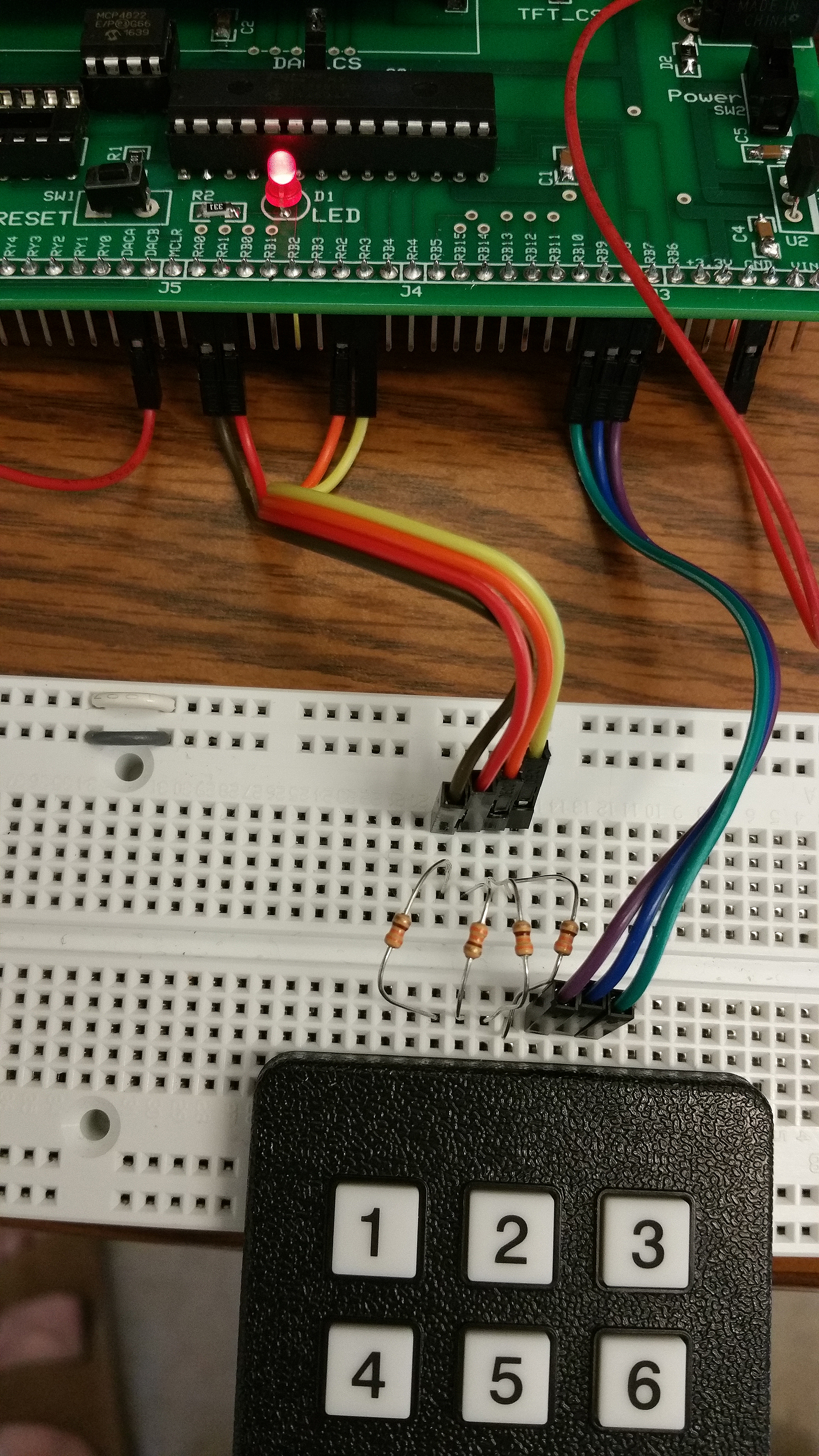
RA0 to RA3 must have the 300 ohm resistor in series! you can see these here.
Make sure that you disable any other use of A0, as noted above.
- Using Port Expander pins
Keypad setup and keyboard scanner code for the Big Board is in the Keypad with port expander example on the development board page.More keypad wiring information is available on the same page in the section Port Expander Details.
The PE_CS jumper must be mounted for the port expander to work.
Nota Bene! IF you use the port expander, then using SPI channel 2 becomes a critical section which must be properly handled in the thread and the DAC ISR (code)!
SPI DAC
- The SPI DAC you will use is the MCP4822. The DAC analog output is marked DACA or DACB on the SECABB
The SPI connections are supplied on the Big Board (SECABB), as long as you connect the DAC_CS jumper.
Section 5.1 and 5.2 of the MCP4822 datasheet discussed the way the the DAC uses SPI.
The DDS example above shows the logical SPI setup.The edge connector pin marked DACA or DACB will go (optionally through a low pass filter) to an audio socket, to be connected to the green audio plug of the speakers. If you are going to design a lowpass filter for the DAC, then you need to know that the input impedance of the speakers is around 10 Kohm.
Audio socket 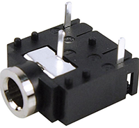 . The pin nearest the socket is ground. Wire the left/right channels together.
Speaker audio input plug 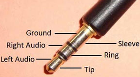 The body of our plugs are green.
Threads:
In this lab and every lab, make sure you are running Protothreads 1_2_2 or later.
I suggest organizing the code as:
- Protothreads maintains the ISR-driven millisceond-scale timing for you
- Timer ISR running at the DDS sample rate to update the DDS and the DAC.
(Lecture explaining the keypad scanner, debouncer, and DDS sample rate, Another lecture on DDS)
- Main sets up peripherials and protothreads then just schedules tasks, round-robin.
- Keypad Thread
- waits for 30 mSec.
- scans the keypad
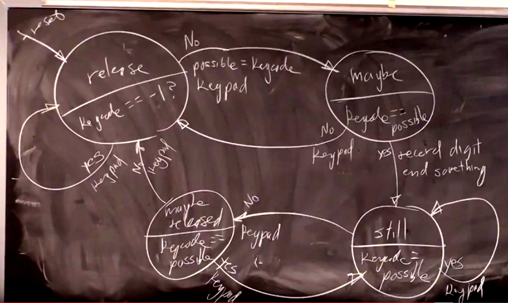
- runs the debounce state machine you will need a state machine that debounces all 12 keys.
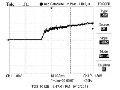
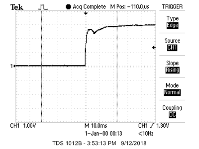
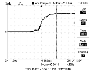
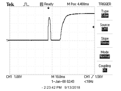
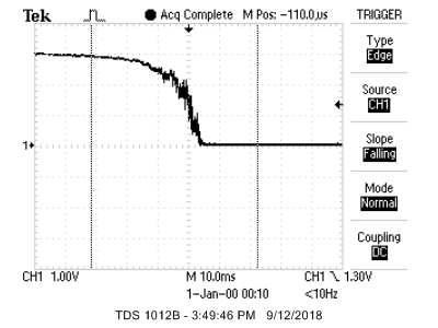
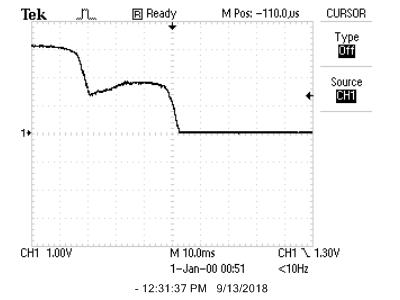
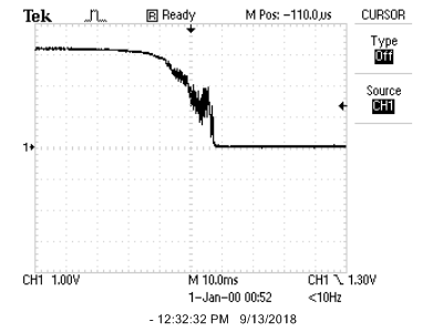
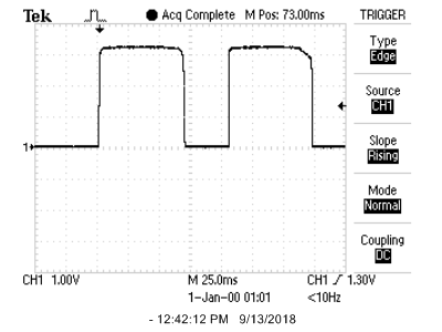
Actual waveforms taken from the keypad: push (1, 2, 3, 4, 5), release (1, 2, 3), Two button pushes, as fast as I could.
(Lecture explaining the keypad scanner, debouncer, and DDS sample rate)
(state machine pseudocode for ONE button, but use the state machine explained in the lecture)
(State machine for 12 buttons explained in the lecture)
- places valid keypresses into a digit buffer and triggers tone burst production for the key pressed
- handles erase/start commands
- detects test mode. see below.
- sets the DDS parameters for two sine waves (or one sine wave in test mode)
and triggers tone burst (or continuous tone in test mode) if necessary.
- Starts/stops the play back
Week one required checkpoint
By the end of lab session in week one of the lab you must either have:
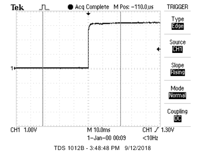
- A low distortion sinewave by DDS synthesis verified by oscilloscope
- Keypad logging of presses to the TFT
Assignment
- Write a Protothreads C program which implements a DTMF generator with the following
specifcations:
- The keypad will be used to enter up to 12 digit telephone numbers.
As each digit is pressed, the two sine waves in the table below will be generated and added together, then modulated.
You must debounce the keypad.
- Pressing the
* button erases the entire stored phone number.
- When the
# button is pressed, the DTMF signal for each entered digit is produced for at least 65 millseconds to simulate dialing of the digits.
Each digit pressed implies that two sine waves play at the same time, as shown in the table below.
There should be at least 65 millseconds of silence between each digit (as per DTMF standard).
- Each tone burst (sum of two sine waves) should ramp up to full amplitude over a time of about 5 milliseconds and ramp down again in about the same amount of time. Ramping the amplitude will decrease the broad band Fourier components which tend to add an annoying click to the sounds. The ramp need not be linear, but could be.
Example matlab code.
- Frequency accuracy should be +/-1.5% (as per DTMF standard) Generate sinewaves using DDS.
The sinewaves should be built from
16-bit samples (taken from a 256 entry table and scaled to 12 bits for the DAC).
- Implement a test mode in which each of 7 DTMF frequencies can be individually measured for frequency accuracy.
Add a push button or toggle switch on the white board to control the frequency test mode. During test mode,
pressing the buttons 1 through 7 should produce one of seven single-frequency sine waves for as long as you hold the button.
You will need to display the FFT of the 7 frequencies to show that all spurous frequencies are lower than -20 db from main tones.
A table of DTMF frequencies:
| Freq |
1209Hz |
1336Hz |
1477Hz |
| 697Hz |
1 |
2 |
3 |
| 770Hz |
4 |
5 |
6 |
| 852Hz |
7 |
8 |
9 |
| 941Hz |
* |
0 |
# |
- Connect the DAC output to a speaker audio input (green phone plug, see below) and listen
the output.
This will aid in debugging and is required for the demo.
- Demo this program to a staff member. Show that all specifications are met
by verifying frequencies with an oscilloscope.
- At no time during the demo should you need to press RESET.
- Your written lab report should include the sections mentioned in the policy page, and :
- How you generated the freqencies (DDS resolution, etc) and an measurement
of how accurate they are.
- Oscilloscope capture of typical waveforms.
- Oscilloscope capture of FFT to show that harmonic distortion meets the DTMF spec
- How you generated the various time intervals required by this project.
- A diagram of the state machine you used to debounce. One of the TAs (Shiva) recommends drawing FSM with fizzim.
- Other design aspects of the assignment, such as the conversion from
user input frequency in Hz to DDS increment.
- A heavily commented listing of your code.
Copyright Cornell University
September 14, 2018