EE 476: Laboratory 0
Learning the hardware and software.
Introduction.
This assignment introduces you to the software and hardware development tools
you will use this semester to work with the Atmel MEGA-series microcontroller
(MCU) chips. You will use the STK500 development board to run some C programs.
The STK500 pushbuttons, LEDs, and a serial connection to the PC will be used
to demonstrate basic compiler, i/o, and debugging techniques. You will run demo
programs, use a debugger, and make
minor modifications to the existing programs.
Hardware
The hardware you will be using to
support the AT90-series is the Flash MCU evaluation board, a small board providing:
- A target AT90-series microcontroller (mcu) with onboard flash program memory.
- A programmer for the target flash memory, including a programmer serial connection
to a PC.
- A separate serial connection for applications.
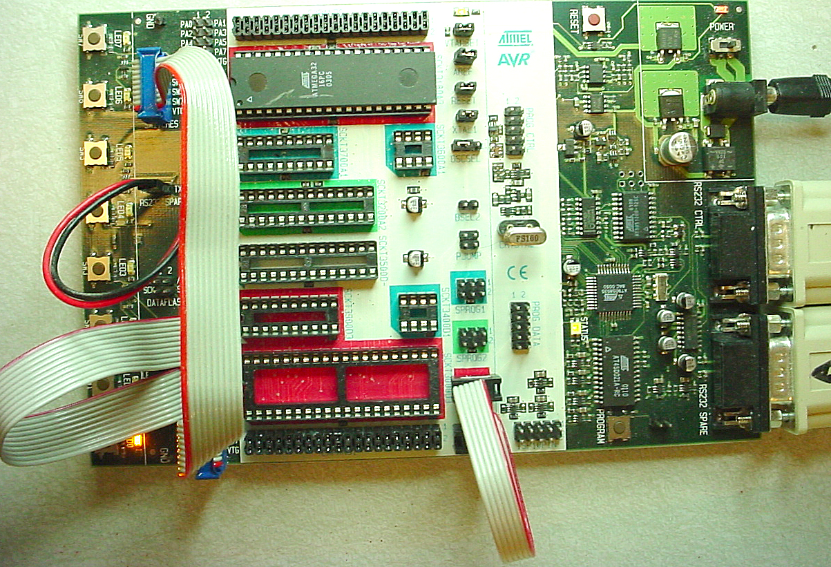
- Eight general pushbuttons, eight LEDs and a RESET button. For this lab, connect the LEDs and pushbuttons with jumpers as shown at the left below. You will need a 2-pin jumper for serial communication (black and red below). You will also need to have a programming jumper as shown on the bottom-center. The crystal socket is shown with a 16 Mhz crystal mounted there. The top serial connector (to the right) is the programming connector, the bottom one the application connector. In this lab, it is used for debugging. For more detail refer to the hardware manual.

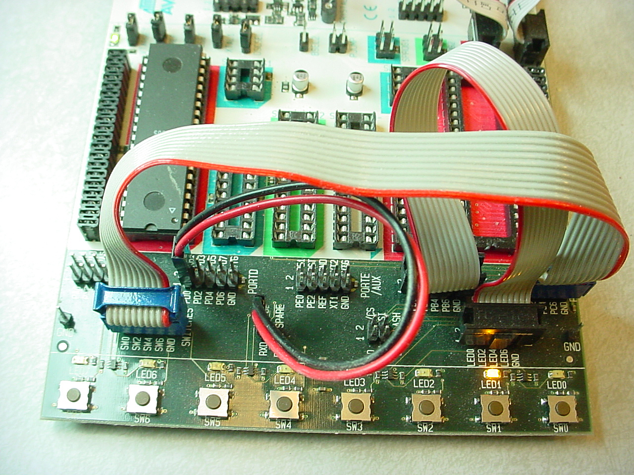
Closeup of application jumpers. PortC is jumped to switch header, PortB to LEDs and the red/black jumper connects serial communication.

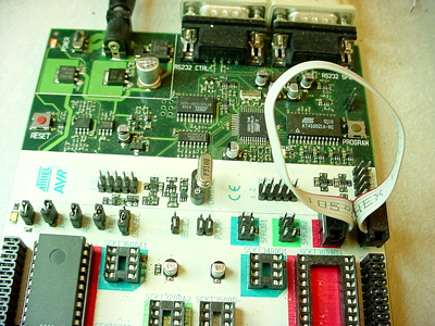
Closeup of programming, reset, power, analog reference and crystal select jumpers jumpers.
- For most labs, you will use 10-pin connectors connectors for bringing out the microcontroller signals to user-designed
peripheral equipment. Note that there is no protection on these lines. You
are connecting directly to the mcu. Prudent design suggests you might want
to use buffers when you are uncertain of voltage levels or other conditions.
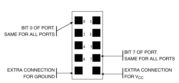
The pin definitions for the connectors are shown below. The inner squares
represent pins. In the image above, pin 0 of each connector is at the top-left.
- There are cables connecting the 10-pin header plugs shown above to DIP plugs
to make it easy to connect to the usual white protoboards. The connection
pin-out is given below along with a picture of the cable attached to PORTB of the STK500 and to a white board..

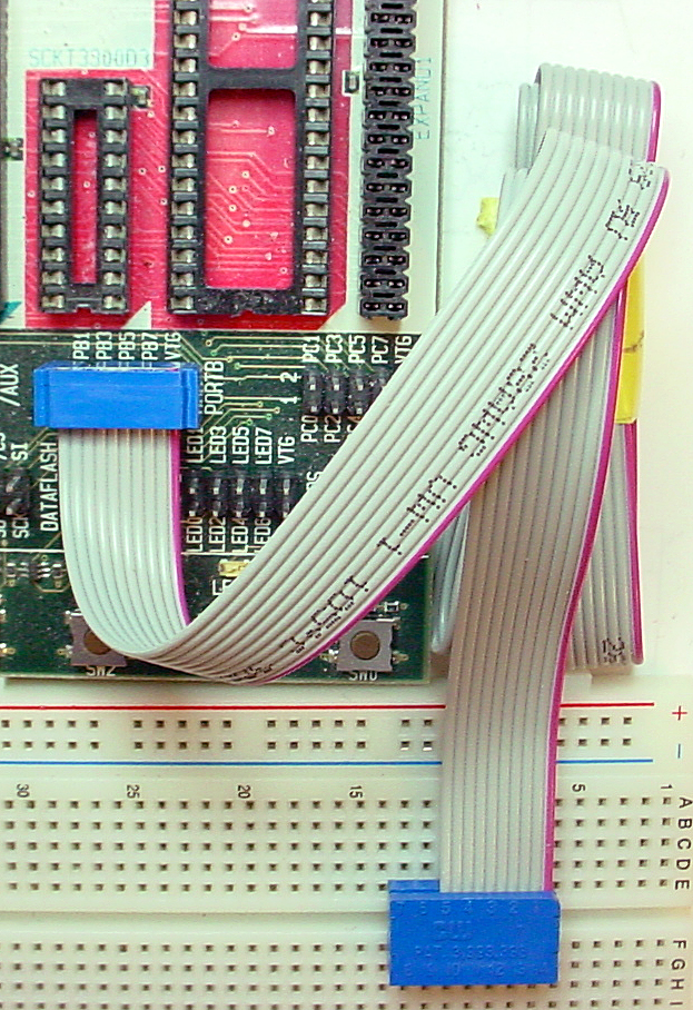
In this lab you will use this cable to add an LED to the circuit as shown below. The positive lead of the LED is slightly longer.

A small power supply provides power to the development board. The demo codes
given in this lab are written for the MEGA32, but many of the examples throughout
the 476 web site are written for the 8515 or MEGA163 mcus. This year we are
using the MEGA32 which has more memory. To run the 8515 or MEGA163example programs
you will need to:
- Change the header file to
<Mega32.h>
- You will need to program the clock select bits in the CodeVision setup:
choose all bits unchecked.
- TIMSK bit definitions are different from the 8515. You must modify any reference
to TIMSK.
- UART register names have changed.
- The programmer cable connects to the PC serial port.
Software
Software you will use consists of:
Special Note
Some Mega32s are being shipped with the internal clock activated and set to 1 MHz. The symptom will be a Failure to program flash error. To program these MCUs in Codevision you must:
- From the main Codevision window: Choose menu
Tools...Chip Programmer.
- In the resulting dialog box:
- set cpu clock to 1 MHz
- uncheck all fuse bits
- choose menu
Program...Fuse Bits
- set cpu clock back to 16 MHz
- close chip programmer dialog box
- The normal make/program dialog should now work.
Procedure:
- Make sure the evaluation board is connected to power and to the PC as specified
in the evaluation board description. Turn on the power supply with the switch
on the board. An LED in the middle of the board should cycle from red to yellow
to green. For this first lab, there should be jumpers on the PortB to the
LED header and on PortC to the switch header. Ask your instructor for help
if these are not installed. There should be a two wire connector from pins D.0 and D.1 to the RS232 jumper.
- There will two serial connections to the STK500. One for programming the Mega32 and one for serial communication between the running program and the PC, which will be running hyperterm. Set up hyperterm for 9600 baud, no parity, 1 stop-bit, no flow-control.
- Put all files on your
Z drive! Do not creat a project in /cvavr/bin.
Be sure to put all your files there and to back up daily!. Only open or save files in your own documents folder.
- There should be a shortcut to Codevision C on the desktop. Do NOT open or save projects into the Codevision bin directory (this is the default)! They will be deleted automatically! Only open or save files in your own documents folder.
- To invoke hyperterm on the PC, you will need to use
Start...Run...hypertrm from the Windows Start menu.
Connect hyperterm to whatever serial port the USB dongle configures. Use Control Panel...System...Hardware Tab...Device Manager Button...+Ports to find out which serial port is connected to the USB dongle.
The STK500 serial port RS232 Spare will be connnected to the dongle.
- After you define a new project, you can add a C source file and edit it.
- Save this code into your
z drive. This program blinks LEDs and
responds to buttons. It is organized as three task subroutines. You will
modify this code in the assignment below.
- In the Codevision file menu choose to make a new file. When the prompt
comes up, choose
Project. When asked if you wish to use CodeWizard,
decline the offer. At this point, you have made a new project, now you
need to configure it. The configure dialog should be open but if it is
not, under the Project menu, choose Configure...
- In this dialog box, in the
Files tab, add the source code
to the project you just defined.
- In the
Compiler tab, set the Chip type to Mega32.
Set clock speed to 16 MHz.
Set (s)printf features to int,width.
- In the
After make tab, set
the Program the Chip checkbox.
Clear all CKSEL check boxes.These select the clock
source.
You may need to uncheck the Check Signature box if the programmer throws an error.
Then close the configure dialog.
- In the
Settings...terminal menu, set the progrmming port to COM6.
We will not use the Codevision Terminal. Setting to COM6 just gets it out of the way.
- In the
Settings...programmer menu, set the progrmming port to COM1.
- Click on the compile icon. A message window will open to tell you if
there are errors in the code. If there are errors, The open the listing
file to see where they are. If the compile is successful, you should be
able to download the program to the STK500 board and see some blinking
LEDs. You will need to change PORTD to PORTC in the code for the switches to work.
- Timing of all functions in this lab, and every exercise in this course will be handled by interrupt-driven counters, not by software wait-loops. This will be enforced because wait-loops are hard to debug and tend to limit multitasking. Specifically, you may not use the delay library routine
delay_ms. Using delay_us will be acceptable when you need to produce delays on the order of a few microseconds.
Assignment
- Using the short demo code downloaded above, modify the code:
- To stop blinking LED 1 when button 1 is pushed.
- To use PORTC rather than PORTD for switches.
- Add an LED and 300 ohm resistor as shown above. Make your program blink this LED rather than the one on the STK500.
- Using the short demo code downloaded above, include the debugger we wrote.
- Follow the directions on the debugger page for modifiying the target program to run with the debugger. If you uncomment the receive ISR enable in
debugger.c, you will be able to get a command line using <cntl-c>.
- Further modify the demo code's task 3 to enter the debugger (using a
debug(3) statement) when you push button 7. Just before your code enters the debugger, insert assembler code to set data register 1 to 0x55, then clear data register 2. See the complete instruction set document for information on assembler instructions.
- Once in the debugger use interactive commands to verify that register one was set correctly.
- Examine and explain the bits in the status register (which should reflect the results of the clear operation).
- With your modifed program, and using only interactive debugger commands:
- turn on all the LEDs by modifying the appropriate i/o register.
- turn off all the LEDs by modifying the appropriate i/o register.
- modify the
led variable in the program to display 0xaa. Consult the *.map file generated by the compiler to find out where the variable is stored.
- determine the amount of hardware stack space used by the program at the time it entered the debugger.
- modify the target program's timer0 prescaler from 64 to 8, then reenter the program (using the interactive
g command) to show that it blinks the LED faster.
- Modify the demo program to define a local variable in task2 and use the debugger to show it was stored in data register 16.
- Modify the demo program to force the
led variable into RAM using the #pragma regalloc- pragma. What is its address?
- Make sure that
#define use_reporting near the beginning of debugger.c is uncommented. Modify the demo program task 2 to include a reportVdec(tsk2c). Insert the statement into the code so that you can see every count of the state variable.
- Make sure that
#define use_logging near the beginning of debugger.c is uncommented. Modify the demo program to log 6 values of the led variable.
- Leave all debugging statements in your program, but insert the line:
#define nullify_debugger just before the debugger include statement. Examine the complier's assembler output file to verify that all instructions corresponding to the debugger have been eliminated from the program.
There is NO written lab report for this exercise, but your attendance is mandatory and your performance in lab will be included in the lab 1 grade.
Copyright Cornell University Dec 2007