Cornell University ECE4760
More I/O for
Pi Pico rp2040/2350
You may find that you need more i/o pins either for analog inputs or digital i/o. The stock Pico or Pico2 has 23 digital gpio pins (gpio0 to gpio22) and three pins which may be configured for digital or analog (gpio26, 27 and 28). The configuration used for most of the lab exercises in ece4760 uses 6 to 10 digital pins for VGA video. Moving to HDMI output on the rp2350 requires 8 digital pins (gpio 12 to gpio19). In addition, one SPI channel is used to control a high-speed DAC for audio synthesis. This DAC uses 4 digital gpio pins. Also, two digital pins are used for serial communication to a host PC. The net result is that you have about 10 digital pins left for any other peripherials.
Quite often student projects need more digital i/o and many projects could use 4 or more analog inputs. A typical example might be two analog joysticks, which require 4 analog input channels. Another example would be a keypad which requires 7 or 8 digital i/o pins for scanning, but can be fairly slow. Below are some ideas on how to solve i/o limitations. Generally, there will be some tradeoff when adding i/o, perhaps speed, or current drive capabilities, or bi-directional (input and output) limitations. Think carefully about what you need. Do you really need to sample the ADC at 100 KHz for a joystick? Can you tolerate a 1 MHz output rate to 8 additional digital outputs. Are you driving LEDS, which require milliamps of current, or a FET, which requires microamps?
More Analog I/O
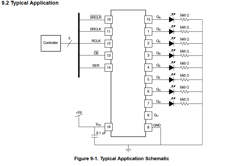
More Digital I/O
Copyright Cornell University August 5, 2025