James Du (jsd46)
Peter Greczner (pag42)
|
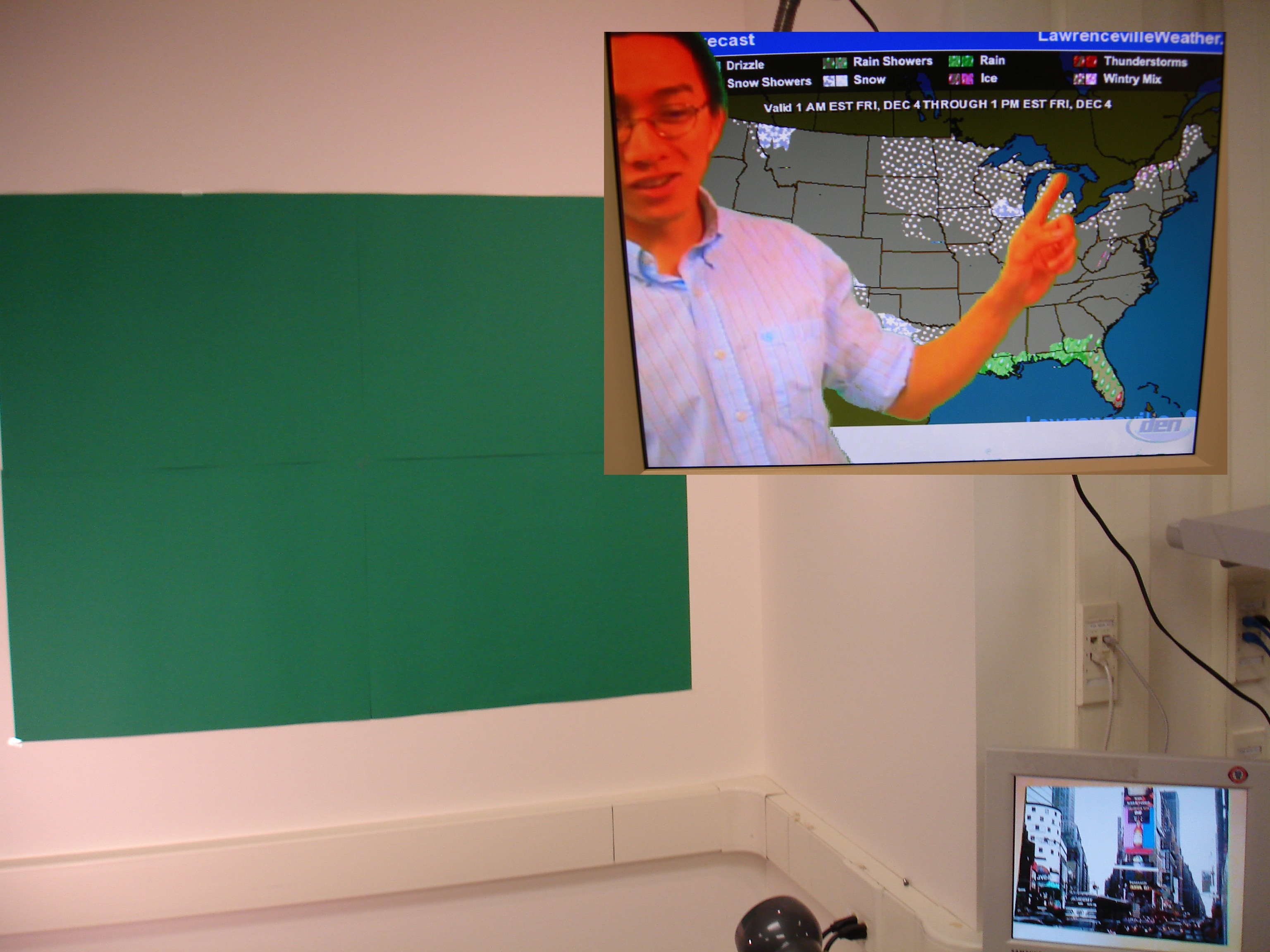
Our project idea is ubiquitous in special effects used in many TV shows, movies, and weather broadcasting.
The project can be divided into four main components. These include RS-232 transfer of background image, video acquisition, effects generation, and effects multiplexing out to VGA. 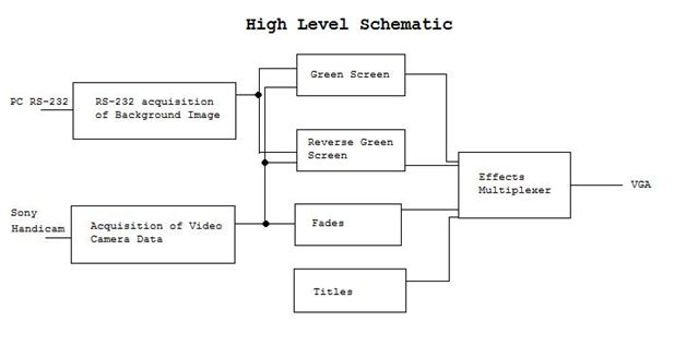 We decided to implement and test each of the effects (green screen, reverse green screen, image transfer, etc.) separately, and then integrate them on top of each other in the main module. The fading in and out effect took precedence over all of the other effects since it controls whether or not the other effects would be displayed at all. Writing text to the screen took precedence over the green screen and reverse green screen effects because text should be written over all video regardless of whether or not the video is straight from the camera or from an image stored in SRAM. Green screen and reverse green screen effects have the same precedence since they are never used at the same time. We decided to implement and test each of the effects (green screen, reverse green screen, image transfer, etc.) separately, and then integrate them on top of each other in the main module. The fading in and out effect took precedence over all of the other effects since it controls whether or not the other effects would be displayed at all. Writing text to the screen took precedence over the green screen and reverse green screen effects because text should be written over all video regardless of whether or not the video is straight from the camera or from an image stored in SRAM. Green screen and reverse green screen effects have the same precedence since they are never used at the same time. Part of our specification was to have an image displayed in the green portion of the video, such as when a weatherman has a map in the background. We decided to store this image in SRAM and load appropriately when creating the green screen effect. To store the image in SRAM we used RS-232 serial communication to transfer the image from a PC to the FPGA. On the FPGA we implemented both a UART receiver and transmitter module. These modules were capable of sending at varying baud rates, error checking, and issuing a timeout error on packet reception. Five different image transfer modes were implemented: 640x480 8-bit bitmap, 320x240 8-bit bitmap stretched in the x-axis and y-axis, 320x240 8-bit bitmap stretched in x-axis only, direct draw mode, and 320x240 black and white image stretched in both x and y axes. Switches, push buttons, a PS/2 keyboard and PC executables were used to enable different types of produced effects. The final image after all effects processed was a 640x480 color image on a VGA capable monitor. Usage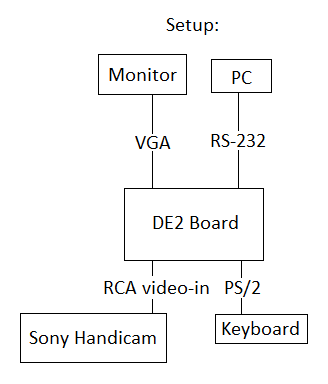 Download our design to the DE2 board and make sure everything in the diagram above is properly hooked up. Initially all effects are turned off and video feed from the Sony Handicam is directly displayed to the VGA monitor. - To turn on/off in effects, press KEY 2. (To check if effects are turned on, point to Handicam at the green screen) - To use the green screen effect, set switch 16 up. - To use the reverse screen effect, set switch 16 down. - To transfer 320x240 images, set switch 0 up, and switches 1 and 2 down; then run im.exe - To transfer 320x240 images in black and white mode, set switch 2 up, and switches 1 and 0 down, then run bw.exe - To transfer 640x480 images, set switch 2 down, and switches 1 and 0 up; then run im.exe - To write text to the screen, start typing on the keyboard; text should appear in the middle of the screen. |