Simplified Floating Point for DSP
Cyclone2 and Cyclone4 version
ECE 5760, Cornell University
Full IEEE 754 floating point (FP) uses a lot of hardware resource on the FPGA. For parallel DSP it would be nice to have a simpler, narrow word FP. Some papers (Fang, et.al., Tong, et.al., Ehliar, et.al.) suggest that only 9 to 11 bits of mantissa is enough for video or audio encoding, as long as there is sufficient dynamic range supplied by the exponent. This page shows a possible implementation. The obsolete Altera documents fp_mult and fp_add_sub (see references) were useful.
A student (Skyler Schneider, 2010) built a similar system with 18 bits of mantissa.
His system is described below.
A student (Mark Eiding, 2015) modified the 18 bit system for faster inverse square root (for gravity calculations):
- C-to-Reg27 conversion,
- Verilog FP hardware
- Format:
bit 26: Sign (0: pos, 1: neg)

    bits[25:18]: Exponent (unsigned)

bits[17:0]:  Fraction (unsigned)


(-1)^SIGN * 2^(EXP-127) * (1+.FRAC)
- Example:
-25.0

    ((-1)**1) * (1.100100000000000000) * (2**(131-127))

    -1     *      1.5625            *      16

    1 10000011 100100000000000000

    0x60E4000
- If the exponent is zero then the value should be treated as zero independent of the mantissa
Simplified, 8-bit exponent and 9-bit mantissa, Floating point.
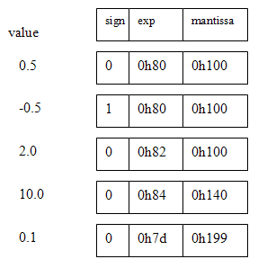
I decided to build a FP with 8-bit exponent and 9-bit mantissa (and with no NANs, infinities, denorms or rounding). The sum of the bit-lengths (plus one sign bit) means that the FP number fits into a 18-bit M4K block word on the CycloneII FPGA. The 9-bit mantissa means that only one hardware multiplier (out of 70) is used for the floating multiplier. The exponent is represented in 8-bit offset binary form. For example 20=128, 22=130, and 2-2=126. The mantissa is represented as a 9-bit fraction with a range of [0 to 1.0-2-9]. A sign bit of zero implies positive. The Verilog representation is {sign,exp[7:0],mantissa[8:0]}. Denormalized numbers are not permitted, so the high-order bit (binary value 0.5) is always one, unless the value of the FP number underflows, then it is zero. No error detection is performed and there is no rounding. There are no NANs, infinities, denorms, or other special cases (which make little sense in a realtime system anyway). Some example representations are shown below.
Five operations are necessary for floating DSP. They are add, negate, multiply, integer-to-float, and float-to-integer. Negate is easy, just toggle the sign bit. The integer conversion algorithms are necessary because the audio and video codecs are integer-based. Outlines for the functions are below. Finally, the modules were tested by building IIR filters. The SOS filters shown below validated the performance of the floating point. An article written for Circuit Cellar Magazine describing this floating point is available.
Multiply algorithm:
- If either input number has a high-order bit of zero, then that input is zero and the product is zero.
- The output exponent is
exp1+exp2-128 or exp1+exp2-129. If the sums of the input exponents is less than 129 then the exponent will underflow and the product is zero.
- If both inputs are nonzero and the exponents don't underflow:
- Then if
(mantissa1)x(mantissa2) has the high order-bit set, the top 9-bits of the product are the output mantissa and the output exponent is exp1+exp2-128.
- Otherwise the second bit of the product will be set, and the output mantissa is the top 9-bits of
(product)<<1 and the output exponent is exp1+exp2-129.
- The sign of the product is
(sign1)xor(sign2)
Add algorithm:
- If both inputs are zero, the sum is zero.
- Determine which input is bigger, which smaller (absolute value) by first comparing the exponents, then the mantissas if necessary.
- Determine the difference in the exponents and shift the smaller input mantissa right by the difference. But if the exponent difference is greater than 8 then just output the bigger input.
- If the signs of the inputs are the same, add the bigger and (shifted) smaller mantissas. The result must be
0.5<sum<2.0. If the result is greater than one, shift the mantissa sum right one bit and increment the exponent. The sign is the sign of either input.
- If the signs of the inputs are different, subtract the bigger and (shifted) smaller mantissas so that the result is always positive. The result must be
0.0<difference<0.5. Shift the mantissa left until the high bit is set, while decrementing the exponent. The sign is the sign of the bigger input.
The multiplier takes about 60 logic elements plus one hardware multiplier on the CycloneII FPGA, while the adder takes about 220 logic elements. The timing analyser suggests that the purely combinatiorial multiplier should be able to run at 50 MHz and the adder at 30 MHz or so.
The integer-to-FP and FP-to-integer conversion routines allow you to specify a signed scale. Going from integer to float, the resulting floating point number is (integer_input)*2scale_input. This feature allows you to convert numbers less than one. Going from float back to integer, you choose the scale you want to bring the floating point number back into a small integer range. The signed integer inputs and outputs are 10-bit, 2's complement format.
Integer to FP:
I assumed 10-bit, 2’s complement, integers since the mantissa is only 9 bits, but the process generalizes to more bits.
- Save the sign bit of the input and take the absolute value of the input.
- Shift the input left until the high order bit is set and count the number of shifts required. This forms the floating mantissa.
- Form the floating exponent by subtracting the number of shifts from step 2 from the constant 137 or (0h89-(#of shifts)).
- Assemble the float from the sign, mantissa, and exponent.
FP to integer:
Converting back to integer is similarly simple, but no overflow is detected, so scale carefully.
- If the float exponent is less than 0h81, then the output is zero because the input is less than one.
- Otherwise shift the floating mantissa to the right by (0h89-(floating exponent)) to form the absolute value of the output integer.
- Form the 2’s complement signed integer.
Testing the FP routines using IIR filtering by Second-order-sections (SOS)
SOS filters have the advantage (over straight multipole filters) of smaller dynamic range on coefficients, so the numerical stability is better. SOS filters are also more straight forward to do with floating point.
The downside is a few more state variables and a few more multiplies for each filter. A matlab program and function convert filter specifications to Verilog with 18-bit floating point. The top-level module defines filters of order 2, 4 and 6. The project is archived here.
Testing the FP routines using IIR filtering
The fpmult, fpadd, int2fp and fp2int routines were incorporated into the state machine filters described on the FPGA DSP page, example 4. The routines worked, implying that the logic is correct, however a 9-bit manitssa is apparently not accurate enough to implement high-order or narrow bandwidth filters. Second order filters work fine, but 4th and 6th order filters became inaccurate when the filter bandwidth was low. Use the SOS verions above for most actual filters. A matlab program (and associated function) were used to convert matlab-designed filter coefficients to floating point format. The top-level module defines three filters and connects them to the audio in/out. The entire project is zipped here.
FP reciprocal
The ability to take a reciprocal allows division to occur. Reciprocal was implemented Newton-Raphson interation on an initial linear estimate of the reciprocal. This design just tests for static correctness of the method by displaying values on the LEDs. The process is to take the input number, strip off the sign and exponent, compute the reciprocal of the remaining number between 0.5 and 1.0, form the new exponent as 0x81+(0x81-input_exponent) then merge together the input sign, new exponent and new mantissa from a Newton iteration process. The module will run at 14 MHz and uses 3 floating point adders and 4 floating point multipliers.
The algorithm (from http://en.wikipedia.org/wiki/Division_%28digital%29) is as follows, with all operations being floating arithmetic:
-
Form
In_reduced={1'b0, 8'h80, m1} where m1 is the mantissa of the normalized input float. This operation
(with the sign set to + and the exponent set to 0x80), limits the range to 0.5 to 1.0.
-
x0 = 2.9142 - 2*in_reduced ( 0.5<=in_reduced<=1.0)
x1 = x0*(2-in_reduced*x0)x2 = x1*(2-in_reduced*x1)- The reciprocal output mantissa is the mantissa of
x2.
- The reciprocal output exponent
=(in_reduced==9'b100000000)? 9'h102-e1 : 9'h101-e1
because an input value of exactly a power of 2 adds one to the exponent.
e1
FP reciprocal Square Root
A
reciprocal square root function is useful when normalizing vectors (e.g. computer graphics) and con be converted to a square root with just one more multiply.
This design just tests for static correctness of the method by displaying values on the LEDs. The process is to take the input number, strip off the sign and exponent, compute the reciprocal square root of the remaining number between 0.25 and 1.0, form the new exponent, then merge together the new exponent and new mantissa from a Newton iteration process.
The module will run at 11 MHz and uses 3 floating point adders and 6 floating point multipliers.
The algorithm (from http://en.wikipedia.org/wiki/Methods_of_computing_square_roots) is as follows, with all operations being floating arithmetic. The x0 estimate is based on a linear approximation which I thought up.:
- Form
input_exp = (e1[0]==1)? 8'h7f : 8'h80 and
reduced_input = {1'b0, input_exp, m1}
where m1 is the mantissa of the normalized input float. This operation, limits the range to 0.25 to 1.0.
-
x0 = 2.05 - reduced_input with (input 0.25<=reduced_input<=1.0)
x1 = x0/2 * (3 - reduced_input*x0*x0) x2 = x1/2 * (3 - reduced_input*x1*x1)- The reciprocal sqrt output mantissa is the mantissa of
x2.
- The reciprocal sqrt output exponent eout is given by
((m1==9'b100000000 && e1[0]==1) )? eout = 9'h82 + ((9'h80 - e1)>>1) : eout = 9'h81 + ((9'h80 - e1)>>1)
because an input value of exactly a power of 2 with odd exponent adds one to the exponent. e1 is the exponent of the normalized input float.
8-bit exponent and 18-bit mantissa, Floating point (by Skyler Schneider, 2010)
Reg27 floating point

Bit #s   Name   Encode
27       s      1-bit sign (0 positive, 1 negative)
26:18    e      8-bit exponent (2's bit complement -128 to 127)
17:0     f      18-bit fraction (unsigned)

Value = ((-1)**s) * (0.f)_bin * (2**e)
** is exponentiation
_bin means a binary interpretation

Example: -1.25
((-1)**1) * (0.101000000000000000) * (2**1)
So the Reg27 floating point value is
1 00000001 101000000000000000
0x4068000

The top bit of f should always be 1 except when
the register stores the value 0, in which case
the entire 27-bit register should be 0.

The multiplier is single-cycle.

The adder takes two cycles and is buffered midway.
It can be pipelined (one add in first half of
adder while another add in second half).

The adder can be used to subtract by flipping the
sign bit of the inputs.

There is no overflow detection.
When underflow occurs, the output is 0.

Parameters used in the routines.

C routines for conversion:

#include ‹inttypes.h›
#include ‹math.h›

// Convert a 27-bit register floating point into a C floating point.
float reg27ToFloat(uint32_t r) {
    uint32_t sign = (r & 0x04000000) >> 26;
    int32_t exp = ((r & 0x03FC0000) << 6) >> 24;
    if(exp > 127) exp -= 256;
    uint32_t frac = (r & 0x0003FFFF);
    float result = pow(2.0, (float) exp);
    result = (((float)frac) / 262144.0) * result;
    if(sign) result = result * (-1);
    return result;
}

// Convert a C floating point into a 27-bit register floating point.
uint32_t floatToReg27(float f) {
    uint32_t f_f = (*(int*)&f);
    uint32_t f_sign = (f_f >> 31) & 0x1;
    uint32_t f_exp = (f_f >> 23) & 0xFF;
    uint32_t f_frac = f_f & 0x007FFFFF;
    uint32_t r_sign;
    uint32_t r_exp;
    uint32_t r_frac;
    r_sign = f_sign;
    if((f_exp == 0x00) || (f_exp == 0xFF)) {
        // 0x00 -> 0 or subnormal
        // 0xFF -> infinity or NaN
        r_exp = 0;
        r_frac = 0;
    } else {
        r_exp = (f_exp - 126) & 0xFF;
        r_frac = ((f_frac >> 6) | 0x00020000) & 0x0003FFFF;
    }
    return (r_sign << 26) | (r_exp << 18) | r_frac;
}
References
JO Hamblen, TS Hall and MD Furman, Rapid protoyping of digital systems: SOPC edition , Springer 2008
Fang Fang, Tsuhan Chen, Rob A. Rutenbar, Lightweight floating-point arithmetic: Case study of inverse discrete cosine transform, EURASIP J. Sig. Proc.; Special Issue on Applied Implementation of DSP and Communication Systems(2002)
Fang Fang, Tsuhan Chen, and Rob A. Rutenbar, FLOATING-POINT BIT-WIDTH OPTIMIZATION FOR LOW-POWER SIGNAL PROCESSING APPLICATIONS, http://amp.ece.cmu.edu/Publication/Fang/icassp02_Fang.pdf (2002)
Jonathan Ying Fai Tong, David Nagle, Rob. A. Rutenbar, Reducing power by optimizing the necessary precision/range of floating-point arithmetic, IEEE Transactions on Very Large Scale Integration (VLSI) Systems, Volume 8 , Issue 3 (2000) Special section on low-power electronics and design Pages: 273 - 285
Eilert, J. Ehliar, A. Dake Liu, Using low precision floating point numbers to reduce memory cost for MP3 decoding, IEEE 6th Workshop on Multimedia Signal Processing, 2004 : 29 Sept.-1 Oct. 2004 page(s): 119- 122
Altera Corp, fp_mult: Floating point multiplier, http://www.altera.com/literature/fs/fsmul_01.pdf, A-FS-04-01 1996
Altera Corp, fp_add_sub: Floating point adder/subtractor , A_FS-02-01, 1996
History:
- Floating point with 8-bit exponent and 9-bit mantissa (no NANs, infinities, denorms or rounding).
The sum of the bit-lengths (with one sign bit) means that the FP number fits into a 18-bit M4K block word on the CycloneII FPGA. The 9-bit mantissa means that only one hardware multiplier (out of 35) is used for the floating multiplier. The exponent is represented in 8-bit offset binary form.
For example 20=128, 22=130, and 2-2=126. The mantissa is represented as a 9-bit fraction with a range of [0 to 1.0-2-9]. A sign bit of zero implies positive. The Verilog representation is {sign,exp[7:0],mantissa[8:0]}.
Denormalized numbers are not permitted, so the high-order bit (binary value 0.5) is always one, unless the value of the FP number underflows, then it is zero. No error detection is performed and there is no rounding. There are no NANs, infinities, denorms, or other special cases (which make little sense in a realtime system anyway).
Multiply algorithm:
- If either input number has a high-order bit of zero, then that input is zero and the product is zero.
- The output exponent is
exp1+exp2-128 or exp1+exp2-129. If the sums of the input exponents is less than 129 then the exponent will underflow and the product is zero.
- If both inputs are nonzero and the exponents don't underflow:
- Then if
(mantissa1)x(mantissa2) has the high order-bit set, the top 9-bits of the product are the output mantissa and the output exponent is exp1+exp2-128.
- Otherwise the second bit of the product will be set, and the output mantissa is the top 9-bits of
(product)<<1 and the output exponent is exp1+exp2-129.
- The sign of the product is
(sign1)xor(sign2)
Add algorithm:
- If both inputs are zero, the sum is zero.
- Determine which input is bigger, which smaller (absolute value) by first comparing the exponents, then the mantissas if necessary.
- Determine the difference in the exponents and shift the smaller input mantissa right by the difference. But if the exponent difference is greater than 8 then just output the bigger input.
- If the signs of the inputs are the same, add the bigger and (shifted) smaller mantissas. The result must be
0.5<sum<2.0. If the result is greater than one, shift the mantissa sum right one bit and increment the exponent. The sign is the sign of either input.
- If the signs of the inputs are different, subtract the bigger and (shifted) smaller mantissas so that the result is always positive. The result must be
0.0<difference<0.5. Shift the mantissa left until the high bit is set, while decrementing the exponent. The sign is the sign of the bigger input.
The multiplier takes about 60 logic elements plus one hardware multiplier on the CycloneII FPGA, while the adder takes about 220 logic elements. The timing analyser suggests that the purely combinatiorial multiplier should be able to run at 50 MHz and the adder at 30 MHz or so. The top level Verilog module is here. The entire project is zipped here. Please note that the hardware not been extensively tested, but see 4 below for the cleaned up, corrected routines!. The filters work correctly, implying that the floating routines are correct.
- Float-to-Integer and Integer-to-Float
Adding integer conversions makes it easier to test the floating point on the FPGA. The Verilog source has int2fp and fp2int modules. The top level module converts switch input integers to floats, multiplies or adds them, converts back to integer and displays on the hex LEDs. The entire project is zipped here. The conversion routines allow you to specify a signed scale. Going from integer to float, the resulting floating point number is (integer_input)*2scale_input. This feature allows you to convert numbers less than one. Going from float back to integer, you choose the scale you want to bring the floating point number back into a small integer range. The signed integer inputs and outputs are 10-bit, 2's complement format. BUT there is a sign-bit error in fp2int which is corrected in the version below.
- IIR filtering to test float routines
The
fpmult, fpadd, int2fp and fp2int routines were incorporated into the state machine filters
described on the FPGA DSP page, example 4.
The routines worked, implying that the logic is correct, however a 9-bit manitssa is apparently not accurate enough to implement high-order or narrow bandwidth filters.
Second order filters work fine, 4th and 6th order filters became inaccurate when the filter bandwidth was low.
A matlab program (and associated function) were used to convert matlab-designed filter coefficients to floating point format. The top-level module defines three filters and connects them to the audio in/out. The entire project is zipped here.
- IIR filtering by Second-order-sections (SOS)
SOS filters have the advantage of smaller dynamic range on coefficients, so the numerical stability is better. SOS filters are also more straight forward to do with floating point. The downside is a few more state variables and a few more multiplies for each filter. A matlab program and function convert filter specifications to Verilog with 18-bit floating point. The top-level module defines filters of order 2, 4 and 6. The project is archived here.
Copyright Cornell University,
March 9, 2017