
Andrew, Jeff, Clifford, and The Bat Hat.
Introduction top
"An ultrasonic range-finding hat with variable haptic feedback for obstacle detection."
-Project Sound Bite
For our ECE 4760 final project, we designed and implemented an ultrasonic range-finding hat that uses haptic feedback to alert its wearer about obstacles in his or her path. The hat is equipped with an ultrasonic transmitter/receiver circuit, which is capable of emitting short pulses of ultrasonic-frequency (approximately 40 kHz) sound, at a level of about 120 dB. These pulses then echo off the closest object in the line of sight of the hat and are picked up by the receiver. The time delay between sending the initial pulse and receiving the echo gives a sense of how far away the obstacle is from the ultrasonic sensor, which can be conveyed to the person by vibrating the hat at a level proportional to that distance. This allows the person to understand what obstacles are in his or her path and to respond accordingly. Specifically, this project is intended as a proof-of-concept/prototype for a product that would ultimately be used by sight-impaired individuals to detect walls or other obstructions, reducing their dependency on canes.
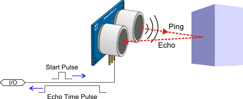
An illustration of an ultrasonic pulse echoing off an obstacle and returning to a receiver.
Source: http://learn.parallax.com/KickStart/28015
High Level Design top
Rationale and Source of Our Project Idea
Many animal species utilize echolocation to identify prey or to better understand their surroundings. Arguably, the most famous implementation of this technique in the animal kingdom is the use of ultrasonic echolocation by bats to understand the size, distance, and characteristics of their prey (insects). However, the use of these principles need not be limited to bats and other animals, but could help humans with guidance and navigation as well, especially humans who are blind and have difficulty understanding their surroundings using “normal” senses. Therefore, the rationale for this project was to design a system that is built upon the principles of ultrasonic echolocation to allow a person with a disability to get around and understand their surroundings more easily.
Background Math
The mathematical foundation for this project is very simple and is primarily based upon acoustic velocity, or the speed of sound, and the time it takes sound to travel a certain distance. At a basic level, this is governed by the following equations:
- Approximate speed of sound in air: v = 331.4 + 0.6T, where T is the temperature in °C
- Round-trip distance = v*t, where t is the time for the pulse to return to the sensor
- Object distance (approximate) = 39*(Round-trip distance)/2 inches
For this project, the speed of sound in dry air at 20 °C and 1 atmosphere pressure was used, which is approximately 343.2 m/s. This value was multiplied by the time difference between when the initial ultrasonic pulse was sent and the echo was received, which gives the round trip distance that the ultrasonic pulse travelled. However, we are interested in the distance to the object off which the pulse echoed, which is half the round trip distance. There are approximately 39 inches per meter, so the object distance in meters is multiplied by 39 to convert the distance to inches. This is the only major calculation done in the main loop of the software.
Logical Structure
The Bat Hat system is structured into four main stages: the pulse transmission stage, the echo detection stage, the distance computation stage, and the pulse width modulation (PWM)/haptic feedback stage. The state transition diagram below reflects the flow of these states during normal operation. These states represent events both in hardware and software and, aside from the distance calculation, each state can (and will in the following sections) be broken down further into hardware and software components.
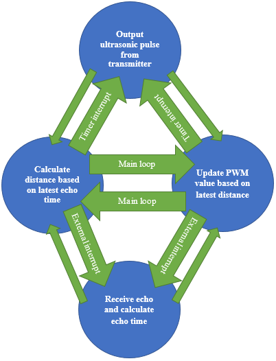
Diagram of four main hardware/software system states.
At a high level, the core of the system is based around three software interrupt service routines (ISRs). One ISR, a rising and falling edge triggered external interrupt, is used to receive echoes and record their arrival times and durations. The next ISR is used to drive a consistent echo pulse train to the transmitter and reset system time when appropriate. The third ISR increments system time. The main loop of the program then updates the PWM value used to control the haptic feedback vibration motor.
The hardware is closely associated with the software. The transmitter consists of an oscillator circuit that drives the ultrasonic transmitting speaker at 40 kHz and is controlled by a single TTL pin, which is driven by a microcontroller port. This creates a train of short ultrasonic pulses, which hit the ultrasonic receiver, reflect off the nearest object, and return to the receiver. The receiver circuitry filters and amplifies the signal and drives a trigger that tells the microcontroller when there is a wave present.
As was stated previously, the time between the initial pulse and the reflected pulse at the receiver, as well as the duration of the two pulses, is recorded by the microcontroller. Any further echoes are ignored because they are unnecessary for determining the distance of the nearest obstacle.
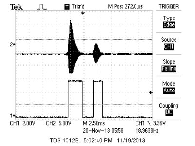
Scope trace of the initial pulse and echo, as seen at the receiver. The top trace is the received signal after amplification and filtering. The bottom trace is the trigger output, which is fed into the microcontroller.
Hardware and Software Tradeoffs
We chose to implement the most complex parts of our project in hardware. This was done in order to allow for more accurate timing and to eliminate the need for an external ADC (the microcontroller's internal ADC samples too slowly for an ultrasonic signal). We could also get more power (higher dB) by driving the transmitter with an external source.
In software, we could have made use of a real-time kernel for timing tasks and concurrency management with semaphores, but because an ISR is never interrupted by another ISR, we could simply utilize volatile variables and a well-structured state machine to eliminate the need for the real-time kernel.
This gave us more flexibility with timing in that all three timers were available for our use.
Standards
There are several international standards associated with sounds and their relationships with human beings. One major standard is ISO 532:1975, “Acoustics -- Method for calculating loudness level," which "Specifies two methods for determining a single numerical value of a given sound, the first method is based on physical measurements, such as spectrum analyses in octave bands, the second method is based on spektrum [sic.] analyses in one-third octave bands." ISO 28961:2012, "Acoustics -- Statistical distribution of hearing thresholds of otologically normal persons in the age range from 18 years to 25 years under free-field listening conditions," shows that we are operating well outside of the human hearing range, which is related to ISO 266:1997, "Acoustics -- Preferred frequencies." Lastly, because of the haptic component of the project, ISO standard 9241-920:2009, “Ergonomics of human-system interaction -- Guidance on tactile and haptic interactions,” "gives recommendations for tactile and haptic hardware and software interactions."
Relevant Patents and Copyrights
There are two patents we found to be relevant to our project. The first is US20120299643, "Driving circuit for a circuit generating an ultrasonic pulse, in particular an ultra-sonic transducer, and corresponding driving method," which is related to the subject matter of our project. However, the approach we use in our design is very different from that in the patent. Another applicable patent is WO2012123787, “An echolocation apparatus,” which, according to the Abstract, “comprises an echolocation module configured to determine a distance to the object based on the received sound signal reflected from an object.” This patent is not as relevant to our project, but does contain interesting ideas related to ultrasonic range-finding.
Additionally, we do make use of the "uart.c" and "uart.h" files, which are under "The Beer-Ware License" and were written by Joerg Wunsch. This is the only copyrighted software we use. There are no other relevant copyrights or trademarks, as far as we know.
Hardware top
Overview
The centerpiece of our hardware is the ultrasonic transmitter and receiver board. This consists of an oscillator circuit used to drive the transmitter at 40 kHz, with a peak-to-peak voltage of 24 V. The input to the oscillator circuit comes from the ATmega1284p microcontroller. The output of the receiver circuitry is fed back into the microcontroller. Additionally, there is an optoisolating circuit used to separate the haptic feedback motor from the rest of the circuitry. The input of this optoisolator circuit is the PWM output of the microcontroller. Lastly, there is a series of switches, which connect the battery packs to the circuitry to provide the necessary voltages (+/- 12 V for the op-amps and microcontroller and 5 V for the haptic feedback motor). An overview of the hardware can be seen in the image below.
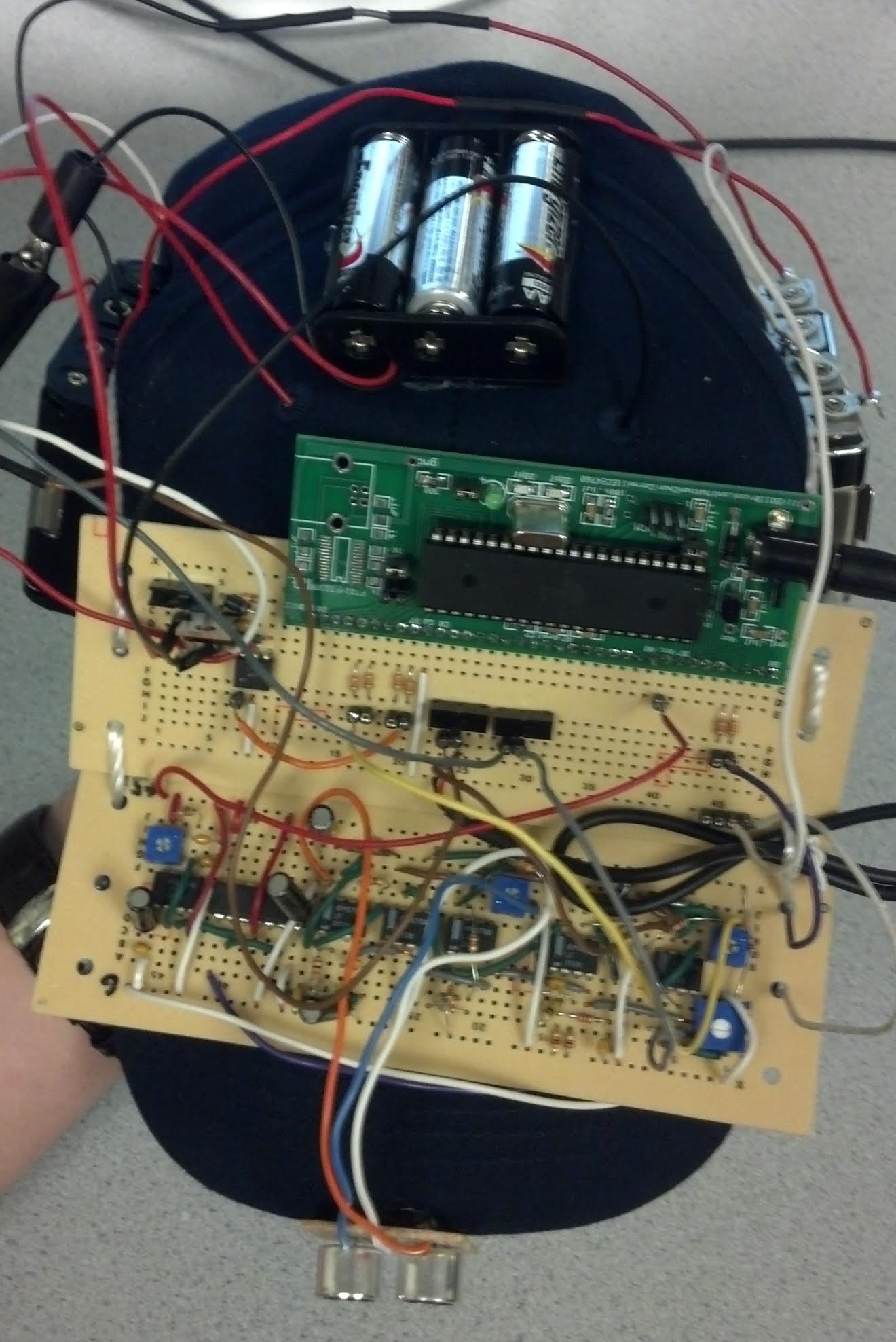
Overhead view of The Bat Hat, showing the full hardware layout.
Transmitter
The transmitter circuitry consists of a 555-timer, which is fed into a D flip-flop, the output of which is high pass filtered, amplified, low pass filtered, and ultimately fed to the input of the ultrasonic transmitter. A block diagram showing the signal flow through the transmitter circuit is below. Refer to Appendix B for a schematic of the ultrasonic transmitter circuitry.

Block diagram of the transmitter circuitry.
555 Timer
The 555 timer generates an 80 kHz signal with an duty cycle that is corrected by the D-flip flop. The 555 timer is operating in astable mode.
TTL D Flip-flop
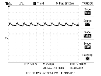
The D flip flop acts as a frequency divider (by a factor of 2) and as an on-off switch. As a result of frequency division, the output is a 40 kHz signal with a 50/50 duty cycle (i.e. a square wave). The CLR feature of the D-flip flop is used to turn on and off the signal without the warm up time that a 555 timer would require. The CLR input is connected to Port B.2 of the microcontroller. The image below shows the sound pulse sent to the transmitter when B.2 goes high.
Transmitter pulse created when Port B.2 is high.
High Pass Filter, 20x Amplification, Low Pass Filter
Since the output of the D flip-flop is 0-5V, the high pass filter centers that voltage at 0V, thus creating a slightly attenuated 40 kHz square wave from -2.5V to +2.5V. This wave is then amplified by 20x to achieve a maximum power 40 kHz square wave, from -12V to 12V, which is then sent through a low pass filter to eliminate any high frequency noise. This results in a signal which looks more like a sine wave. When this signal is passed through the ultrasonic transmitter speaker, some ripple artifacts occur, but they are less pronounced than they would be with a pure square wave signal. The end result is a 40 kHz ultrasonic sine wave driven at approximately +/-12V, which results in approximately 120 dB of sound. As can be seen in the scope trace below, the actual frequency we drive the transmitter with is approximately 40.5978 kHz.

40 kHz waveform used to drive transmitter.
Receiver
The receiver circuitry starts with the ultrasonic receiver, whose output is high pass filtered, amplified, low pass filtered, amplified again, and offset. This signal is then passed through a peak detetector, which is fed into a Schmitt trigger, a negative voltage clamp, and eventually a voltage divider before being fed into Port D.3 of the ATmega1284p. A block diagram showing the signal flow through the receiver circuit is below. Refer to Appendix B for a schematic of the ultrasonic receiver circuitry.

Block diagram of the receiver circuitry.
The receiver receives ultrasonic pressure waves and outputs voltage based on received frequency and driving force. Its center frequency is 40 kHz. At center frequency at close range, the receiver output is on the order of magnitude of 1V. At 6 feet, the order of magnitude is about 10mV.
High Pass Filter, 100x Amplification, Low Pass Filter
This stage is essentially a band pass filter with ~100x gain. The output can have a DC offset since it is not high pass filtered. The raw received signal and the filtered receiver output is shown below, demonstrating why this stage is so necessary. Note the received frequency is almost exactly the transmitted frequency.
Raw signal at the output of the ultrasonic receiver.

Filtered output of the ultrasonic receiver.
5x Amplification
This stage can cause clipping and noticeable DC offset – not enough offset to impact circuit performance. Total gain so far: ~500x from receiver’s initial input.
Summing Amplifier with Post-Buffer
This stage is used to both offset the DC voltage created from amplification and precisely set the voltage output for a grounded input signal to 0.7V, or the turn-on voltage of a diode. The post-buffer is used for its high input-impedance and low output-impedance characteristics.
Peak Detector
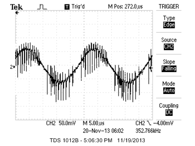
The peak detector is used to follow the positive envelope of the amplified 40 kHz sine wave precisely at the rising edge of the signal. The peak detector has a time constant of 40 microseconds, which is slightly longer than the 25 microsecond period of a 40 kHz sine wave. The falling edge will therefore lag the signal with a time constant of 40 microseconds. Output of the peak detector when no signal is present is 0V, and the output reacts as soon as any positive voltage fluctuation occurs. The input of the peak detector is offset by +0.7V because this is the turn on voltage of the peak detector. An image of the peak detector output, showing it following our 40 kHz signal is below.
Output signal from the peak detector.
Schmitt Trigger
Because the output of the signal needs to trigger a software interrupt, ~500mV of hysteresis is needed to limit the number of rising edges triggered by the fast oscillations of a signal crossing the reference voltage. The optimal reference voltage was found experimentally to be 0.632V, which was chosen to be above most environments' ultrasonic noise floor. The post-buffer is used for its high input-impedance and low output-impedance characteristics. The output of the Schmitt trigger is +12V for a signal that is above the reference voltage and -12V for a signal that is below the threshold voltage. Refer to this image to see how the Schmitt trigger responds to the transmitted signal and echo.
Negative Voltage Clamp
Since a microcontroller doesn’t accept negative voltage values for the chosen input port, it is necessary to clamp any -12 Voltage to ground through a diode. The output voltages therefore range from -0.7V to +12V.
Voltage Divider
Additionally, since a microcontroller doesn’t accept positive voltage values above 5V for the chosen input port, it is necessary to divide the voltage output from the Negative Voltage Clamp down to 5V. The output of the voltage divider is ~0V to 5V, where the lower voltage is close enough to 0V for the microcontroller to treat it as a low voltage.
Microcontroller Port D.3
Finally, the voltage divider is connected through a 330 Ohm resistor to the microcontroller's Port D.3. The software takes over from here.
Haptic Feedback Circuitry
The final component of the hardware is the haptic feedback circuitry, which consists of an optoisolator and the mini vibrating disc motor. The optoisolation is necessary for protecting the microcontroller port from large negative voltage spikes that occur when the motor shuts off. We decided to drive the motor with ~4.5 volts (it can take anything between 2 and 5 volts). Refer to Appendix B for a schematic of our optoisolation and haptic feedback circuit, which is driven with the PWM output from the microcontroller.
Trials and Tests
We tested the hardware extensively. During initial development, the majority of the testing involved determining how to filter the signal in the most reliable way. In later stages of development, most of the hardware testing involved setting the reference voltage for the Schmitt trigger to a value that would be above most environments' ultrasonic noise floor. This was done experimentally by watching the UART console output and tuning the trigger level until the output displayed the values we expected. Additionally, we needed to play with the voltages and PWM frequencies used to drive the vibrating disc motor in order to find something that wasn't too annoying to the user, but still clearly indicated the presence of an obstacle. This was done iteratively by wearing the hat, determining how the feedback felt, changing voltage and software values, putting the hat back on, etc. One thing we tried that didn't work was driving the ultrasonic transmitter with a pure square wave. Although this did transmit a signal, we found that it added more noise to our received signal. This is why we converted the transmitted signal to something more sinusoidal. After extensive testing, we believe that our transmitter, receiver, and haptic feedback circuitry is very functional and reliable.
Software top
Overview
Sending Pulses
The software is used to generate the pulses sent by the transmitter. This is done within an Interrupt Service Routine (ISR), which uses timer 1 to keep a count in order to determine when the output port should be high and when it should be low. The ISR is triggered by a timer 1 compare vector. Timer 1 is set to run at its full rate, 16 MHz, and keep a count that is incremented about every 500 microseconds. In more simple terms, as timer 1 runs, we keep the output high for 500 microseconds by incrementing a count to keep track of the time. The pulse is on for 500 microseconds because that is the time it takes sound to travel 10 centimeters, which is detectable by the receiving speaker. We also have a similar counting system to keep the output low for around 10.5 milliseconds. Since the microcontroller can only store a value of 65535 for each integer (65535 is the maximum int value) and we had to increment to roughly 1680000, we decided to increment up to 60000 twenty eight times. This was done by incrementing another variable to 28 in order to time 10.5 milliseconds, with timer 1 running at the full 16 MHz. The 10.5 millisecond pause was used in order to generate the delay between pulses that we desired. Keeping the pulses 10.5 milliseconds apart allows the microcontroller to detect a pulse from 3.59 meters away (provided sound is travelling at 343.2 m/s under normal conditions). Taking the round-trip distance into account, we would be able to detect a pulse from around 1.8 meters away before another pulse is sent out by the transmitter. Each of these parameters is adjustable in software, which allows us to control our range to best suit our needs.
Calculating Distance
As the pulses are sent by the transmitter, the receiver is constantly on to detect the echoes. The output of the receiver is an input to Port D.3 of the microcontroller, which is used to detect when the receiver goes high (indicating a pulse was received). The change in state of the port triggers an external interrupt on INT1, which is set to trigger on any (rising and falling) edge. When the external interrupt triggers, the microcrontroller updates the echo time based on the time difference between the falling edge of the sent pulse and the rising edge of the received echo, which is later used to calculate distance.
Haptic Feedback and PWM Output
To indicate to the user that echo was received (and there is an obstacle in his or her path), we added haptic feedback via a small vibrating disc motor. To show range, we ran the motor with a PWM signal that varied in frequency based on the calculated distance. We set the PWM signal to run off timer 2, the output of which can be seen at pin D.7 on the ATmega1284p. We scaled the PWM value (OCR2A) based on a maximum distance that we set so that it could fall between 0 and 255 with 0 being the closest distance and 255 for no detection. ([0,255] is the range for the PWM timer.) We implemented a linear model that decreases the PWM to the motor from the minimum distance to the maximum distance, with no response for no echo detection on the receiver.
Function Listing
Main
int main(void)
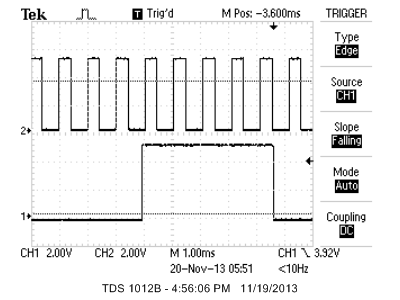
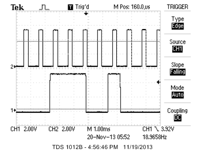
The main function is the entry point for the program and is responsible for calculating the distance to an obstacle based upon the echo time, updating the PWM (OCR2A) value, and turning on and off the LED connected to Port D.2 of the ATmega1284p based upon whether there is an obstacle present. The main function starts by calling the "initialize" function and then jumps directly into an infinite while(1) loop. This loop begins by checking whether the length of the first pulse (the pulse send by the transmitter) is greater than the maximum pulse length that is expected in the "far field" case. The "far field" case is the situation in which the receiver is beyond the 10 cm minimum that is required for a received echo to not "blend" with the sent pulse because it comes back faster than the transmitter can shut off. When this echo "blends" with the sent pulse, we are in the "near field" case. Illustrations of the "near field" and "far field" cases can be seen in the images below.
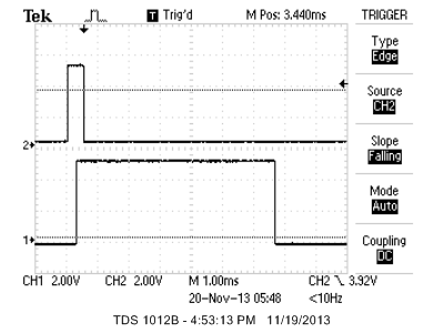
Scope trace showing the near field case, in which the transmitter/receiver is close enough to an obstacle that the echo blends in with the transmitted pulse, making it difficult to discern the distance of the obstacle, although it is known to be less than 10 cm away because of the length of the received pulse. The top trace is the output from the microcontroller to the 555-timer and the bottom trace is the input from the Schmitt trigger.
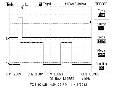
Scope trace showing the far field case, in which the transmitter/receiver is far enough from an obstacle to see two pulses, the transmitted pulse and the echo. Because the transmitter's oscillator circuit takes time to ramp up/down, the actual transmitted pulse is longer than the pulse coming from the microcontroller.
If the length of the first pulse is indeed longer than it should be in the far field case (we called this length expectedMaxNominalPulseLength and set to 2800 microseconds), the distance value is set to 0 (even though it is really in the range [0 cm, 10 cm]). Then, OCR2A is set to run PWM at full speed, which vibrates the motor at maximum intensity because the object is very close, and the LED is turned on, indicating something is in the way.
If the length of the fist pulse is less than expectedMaxNominalPulseLength, which, as can be seen in the image above, the length of the first pulse is typically just less than 2.8 ms (2800 us), then the program deals with this as a normal echo (far field case). In this case, the distance is calculated as described in the third equation of the Background Math section, the PWM value is updated, and the LED is turned on. In the event that there is a UART connected to the microcontroller, the calculated distance will also be printed to console. The following line of code is used to calculate the PWM (OCR2A) value:
OCR2A = (distance <= maxDistance ? ((int) (motorMax + (distance*(motorMin-motorMax)/maxDistance))) : motorMin);
This line ensures that, as long as the distance is less than the maximum allowable distance, the PWM value will be set to a value proportional to the distance to the obstacle.
Lastly, if no pulse is detected, distance is set to "infinity" (65535), the haptic motor is shut off, and the LED is turned off as well.
Timer 0 Compare ISR
ISR (TIMER0_COMPA_vect)
The timer 0 compare ISR is set to interrupt every 10 us. When the interrupt is triggered, a variable called pulseTime is incremented. This time is therefore representative of elapsed 10 us intervals, so in order to obtain the pulse time in microseconds, one must multiply pulseTime by 10 (which is done in main).
Timer 1 Capture ISR
ISR (TIMER1_COMPA_vect)
The timer 1 capture ISR runs at the full rate of the ATmega1284p (16 MHz). This ISR is responsible for generating the pulse train that drives the 555-timer. There are two states in the ISR, pulseOn and !pulseOn. If the pulse is on, the ISR turns it off and sets the timer 1 compare register to count to 60000 (1/28th the time until the next pulse). If the pulse is off, the ISR checks whether 28 iterations of the 60000 count interrupt has occurred. If so, the ISR turns the pulse back on and sets timer 1 to interrupt again after the allotted "pulseDuration" and sets the state back to "pulseOn."
INT1 External Interrupt ISR
ISR (INT1_vect)
The INT1 external interrupt ISR is the most complicated of the three interrupt service routines. The state transition diagram is depicted below. Because the interrupt is set to occur at both the rising and falling edge of the receiver input, the ISR must deal with both of these cases.
In the case that this is a rising edge interrupt, the program will need to distinguish between the rising edge of the transmitted pulse and the rising edge of the received echo. The transmitted pulse is denoted as pulseNumber = 0 and the received echo (if any) is denoted as pulseNumber = 1. Any pulses after these are ignored by setting pulseNumber to anything but 0 or 1. If pulseNumber is 0, the pulseTime variable is set to 0 so that the length of the transmitted pulse can be measured (to distinguish between the near field and far field cases). If pulseNumber is 1, the pulseNumber is set to a value other than 1 or 0 and the variable "echoTime" is updated to be the time between the rising edge of the transmitted pulse and the this rising edge (in 10 us intervals).
Therefore, the only falling edge that matters is that of the transmitted pulse. So, if the interrupt is a falling edge, the program determines whether it was that of the first pulse, and if so, the program updates the "firstPulseLength" variable.

State transition diagram of the INT1 external interrupt ISR.
Initialize
void initialize(void)
The initialize function, which is the first function called in main, sets up the timers, initializes the ports, the UART, and sets up and turns on the ISRs. First, the method turns on the timer 0 compare/match ISR and sets it to interrupt every 10 us. It then turns on the timer 1 compare/match ISR and initializes the compare register to "pulseDuration." Timer 1 has no prescaler and clear-on-match is turned on. Next, timer 2 is turned on. Timer 2's prescaler is set to 256 and all communication ports are initialized. The interrupt function then sets up Ports B and D, so that B.2 is an output. D.2, D.7, and D.1 (the UART) are also outputs. D.3 is used as an input for the external interrupt, which is set to trigger on any edge. Finally, the UART is initialized and interrupts are enabled.
Illustration of PWM Cases
The three images below illustrate the change in the pulse width modulated signal used to drive the haptic motor. Clearly, the farther the obstacle is from the sensor, the lower the PWM becomes. When there is no obstacle present (no echo), the PWM signal is shut off completely.
Near field case, with rapid PWM.
Moderate distance case, showing an echo and moderate PWM.

Far distance case, showing an echo and low PWM.
Trials and Tests
The testing of the software was a constant, iterative process. The most tricky part of the program to write was the INT1 external interrupt ISR. Getting the logic of the state transitions correct was difficult and we went through several designs before we found something that gave us an accurate distance. At first, we set the external ISR to only trigger on the rising edge of the input signal, but we quickly found out this did not work because it would cause erratic behavior in the near field case. Utilizing both edges allowed us to eliminate this erratic behavior with a more complex state machine. Most of the software testing did not involve verifying the functionality of the software logic itself, but mostly involved fine-tuning the parameters used within the software. For example, though trial and error, we found that 10 us interrupts for timer 0 gave the most accurate results. Additionally, we needed to tune each of the "pulseDuration," "expectedMaxNominalPulseLength," "maxDistance," "motorMax," and "motorMin" constants. This was mostly done by placing the apparatus on the table and using a book or other hard surface, along with the UART console output showing the distance measurement, to tune the constants. Eventually, we came across values that worked quite reliably. The motor variables were tuned by wearing the hat to determine what vibration intensity was needed in order to make the obstacles obvious to the user. After all of our trials and testing, our end product became a very robust and reliable program.
Results top
Speed of Execution
The execution speed of our design is very quick. In fact, during normal use of the hat, obstacle detection feels very instantaneous. Technically, the pulses are set to run at a rate of 0.105 seconds (60000 counts)*(28 repetitions)/(16 MHz). This means that the PWM value should theoretically be updated about 9 times a second. However, due to the overhead of entering and exiting ISRs, as well as the overhead of mathematical calculations, the PWM value is actually updated about twice per second. This speed is still plenty fast enough to alert the user to an impending obstacle. In fact, average human reaction time is around .19 seconds, so the user of the hat will be able to receive and respond to the stimulus as soon as it arrives. The maximum range of the hat is approximately 70" under normal conditions, which means that a person jogging in the hat might not be able to stop fast enough to avoid an obstacle, but a person walking at an average speed of 3.1 mph, would certainly be able to stop before hitting an obstacle. This means that the hat is able to detect an obstacle and alert its user to the impediment fast enough to allow him or her to avoid hitting the obstacle, especially if this person is moving cautiously, as a person with a disability would tend to do.
Accuracy
As was mentioned briefly in the previous section, the hat has a maximum range of approximately 70". Anything beyond this range will produce 0 PWM. As was discussed previously, the near field range is between 0 and 10 cm, at which point the hat will vibrate at full strength. Any distance between approximately 4" and 70" will be captured by the software with approximately 1" accuracy. The 1" number comes from the execution rate of the timer 0 interrupt, which triggers every 10 microseconds. In 10 us sound travels approximately 0.1351", so the +/- 1" number is actually conservative, but allows time for the ISR and mathematical calculation overhead. In fact, sound takes about 74.01 microseconds to travel 1". In addition to calculating these conservative theoretical accuracy values, we measured the accuracy of the system using a meter stick. We compared the console output displaying the calculated distance to our meter stick measurement of the distance to the obstacle. The measured distance value was always within 1" of the calculated distance, confirming the functionality of our software, as well as our conservative error calculations.
Safety
Because this system might ultimately be used (after several more design iterations) by a person with a disability, safety is of the utmost priority. We enforced safety in the design by ensuring that all circuitry was as compact as possible and that all batteries and electrical connections were well separated so there would not be an issue with an electrical short. Additionally, we incorporated SPDT switches to all power supplies so that the power to the device is easy to turn on and off and does not involve any plugging in or unplugging of electrical cables. Lastly, we ensured all circuitry was well attached to the hat, so nothing could come off and harm the user. Although it may not be necessary, we even shielded the user from direct contact with the vibrating disc motor by covering it with tape. We would like to make it clear that this design is by no means ready for use by anybody outside of a laboratory setting and will require much more testing and design improvements before it is completely safe for use by a member of the general public.
Interference with Other People's Designs
The ultrasonic transmitter and receiver could interfere with other ultrasonic transmitters and receivers that are designed to operate around 40 kHz. In fact, at one point during a laboratory session, we picked up the ultrasonic transmission of another group with our receiver. (They were < 70" away.) For the most part, however, we do not pick up any unusual noise, environmental or otherwise, during normal operation. We do not believe that the device significantly interferes with other electronic devices. The device may malfunction as a result of 40 kHz noise pollution, but we have never encountered such a thing during testing in non-laboratory environments.
Usability
We are very proud of the user-friendliness of this product. In fact, when we tested it by placing it on a friend's head and asking them to guess what it does, they wore it around for a while and exclaimed, "So is it supposed to train you not to walk into walls?" Clearly, it is immediately obvious to a user when they are facing a wall (or other obstacle) and when they are not. Additionally, if the user angles their head up or down, they can even detect the ceiling or desks and tables in their way, although obstacles on the floor are very difficult to detect. As far as usability by people with special needs, the hat is not yet user-friendly enough for people with seeing disabilities to turn it off and on by themselves, however this is something we would like to add in a later design iteration. Other than turning on the hat, however, the device should be very usable by someone with special needs, although we have not yet tested it on such an individual. Again, we do not recommend relying upon this device for navigation yet and cannot completely guarantee the safety of the user. Overall, the hat works very well and is quite capable of relaying information to its wearer, allowing them to "see" anything in front of them.
Conclusions top
Results vs. Expectations
Overall, our project met our expectations.
We did envision the circuitry being a little more compact than it was, which is possibly something we can improve upon in further design iterations.
We had originally thought we would add extra sensors, but the front sensor works so well that it seems unnecessary.
One idea was to add an additional sensor to the rear of the hat. This is something that might be interesting to add, but might also confuse the user if both a front and back sensor are in use.
We did implement an LED on the front of the hat, which allows somebody watching the hat in use to understand when the user is feeling a vibration. This is something that was not in our original proposal.
Our original proposal stated "we propose to design a hat with one or several ultrasonic transmitter/receivers that are capable of emitting short pulses of ultrasonic-frequency sounds (in the range of 20 kHz to 70 kHz) at a level of approximately 120 dB and sensing when those pulses echo back and hit the source of the sound again. This gives a sense of how far away the nearest object is to the ultrasonic sensor, which can be conveyed to the person via haptic, in this case, vibrational, feedback within the hat. This will allow the person to understand how far away something is in front of him based upon the level of haptic feedback he or she is receiving."
Clearly, we achieved our goal in its entirety with great success.
If given more time, it would definitely be interesting to add more sensors, perhaps sensors of other types, to the hat.
We could also add modes that would make it useful for individuals who don't have sight impairment, but maybe would want such a hat for navigating a dark environment, such as a mine or a work site at night.
This might involve adding an audible warning mode to the hat, in addition to a haptic warning mode.
Overall, we achieved everything we set out to and created a reliable, easy-to-use product.
This device holds a lot of promise for use by people with disabilities.
Granted, we would need to iterate on the design several times to reach a commercially-viable product.
However, this is a great proof-of-concept/prototype of using a wearable ultrasonic sensor, combined with variable haptic feedback, to allow humans to navigate when they might have not otherwise been able to.
Conformance to Standards
We believe we conformed to all the ISO standards we listed above. Additionally, we were sure to conform to our own personal standards of quality and good design process. There is not a large set of standards governing our device, so we mostly had to use our best judgement on what we thought would yield the best quality and safety.
Intellectual Property Considerations
The entire hardware design of this project was done without referencing any other designs or the intellectual property of others. The software we wrote is also mostly of our own design, although we did utilize ideas learned from Bruce Land's example code from the previous labs, we did not explicitly copy any of those programs. We did use the UART.c and UART.h files, which are under the "Beer-Ware License" and were written by Joerg Wunsch. These UART files are not necessary for our final design, as the microcontroller board we soldered does not even have a UART connection, but we did use them for debugging purposes, so we left them in the code. The patents listed previously are only related to our project and we did not directly use any of the ideas claimed within them. We did not reverse-engineer a design, so there should be no patent or trademark issues. We also did not have to sign any sort of non-disclosure to get a sample part or for any other purpose. We do believe that the algorithm we used to determine the near-field state, in combination with our Schmitt trigger, is novel and would not be immediately obvious to somebody in our field. However, we don't wish to pursue any patent opportunities for our project. Conversely, we hope that people will take our design and use it as inspiration to find even better alternatives to help individuals with seeing disabilities navigate more easily. There might be publishing opportunities for our project, which we will continue to explore. Lastly, the source code for this website came from the Hand-Motion Chess project and may have originally stemmed from the Human Tetris project, so a big thanks is owed to both of those teams as well.
Ethical Considerations
Because our project is ultimately intended for use by individuals with disabilities, we needed to remain highly ethical throughout the design process. Specifically, we carefully adhered to the IEEE Code of Ethics, working to stay professional and honest in everything we did. We worked very hard to ensure that our design is "consistent with the safety, health, and welfare of the public." We do not have any conflicts of interest. All of the claims we made on this page about our data are accurate to the best of our knowledge. Furthermore, the entire goal of this project was to "improve the understanding of technology; its appropriate application, and potential consequences," which means that our general motivation for developing this device was very consistent with the general sentiment of the IEEE code of ethics. We believe we have credited all individuals who helped us with this project. Furthermore, we hope that people will contact us with any constructive criticism or ways to improve upon this design and if we made any technical errors in our design, we hope people will reach out to us so that we can correct them. We worked well as a team and made sure that each of us consistently followed the IEEE Code of Ethics every step of the way.
Legal Considerations
As far as we know, there are no legal considerations involved with this project. The only signal we use is a 40 kHz sound wave; we do not use radio communication of any sort, so there are no applicable FCC legal restrictions.
Appendices top
A. Program Listing
- TheBatHat.c (6 KB)
- uart.c (5 KB)
- uart.h (1 KB)
The full repository for this project is available for download at https://bitbucket.org/jbuswell/4760.git or via Git by using the command "git clone https://bitbucket.org/jbuswell/4760.git".
B. Schematics
Schematic of the ultrasonic transmitter circuitry, including 555-timer, flip-flop for dividing the frequency, and operational amplifiers.
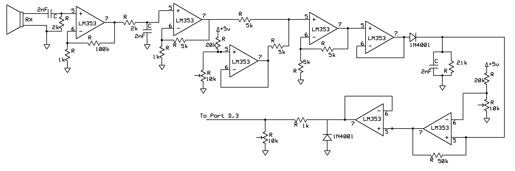
Schematic of the ultrasonic receiver circuitry, including the filters, amplifiers, peak detector, and Schmitt trigger.
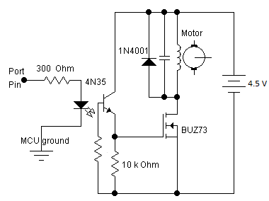
The optoisolator circuit used to separate the haptic feedback motor from the microcontroller.
Source: ECE 4760: Lab 4, Fall 2013
C. Parts List and Costs
| Part | Vendor | Cost/Unit | Quantity | Total Cost |
|---|---|---|---|---|
| Atmega 1284p | Lab Stock | $5 | 1 | $5 |
| Custom PCB | Lab Stock | $4 | 1 | $4 |
| 40 kHz Tx/Rx Pair (Part #139492) | Jameco Electronics | $7.95 | 1 | $7.95 |
| Vibrating Mini Motor Disc (Part #1201) | Adafruit Industries | $1.95 | 1 | $1.95 |
| Large Solder Board | Lab Stock | $2.50 | 2 | $5 | Header Pin | Lab Stock | $0.05 | 50 | $2.50 | SPDT Switch | Lab Stock | $0.73 | 3 | $2.19 |
| LM 353 Op-amp | Lab Stock | $0 | 9 | $0 |
| Hat | Target | $3.95 | 1 | $3.95 |
| AA Battery | Target | $0.42 | 7 | $2.94 |
| 9V Battery | Target | $1.57 | 2 | $3.14 |
| Potentiometer | Lab Stock | $0 | 4 | $0 |
| Wires, Resistors, Capacitors | Lab Stock | $0 | Many | $0 |
| TOTAL: | $38.62 |
D. Division of Labor
The group worked as a very cohesive unit. All three team members were involved with every stage of the process. In general, Andrew was the analog circuit designer, Jeff was the software & solder guy, and Clifford worked to debug everything, implement haptic feedback, and keep the project flowing smoothly. The team spent tireless hours in the lab together working on perfecting the hardware and software to obtain the best range and reliability.
Jeff Buswell
- Designed main software functionality
- Soldered all boards (Tx, Rx, Microcontroller, Optoisolator)
- Debugged circuits and helped tune receiver circuitry
- Obtained all parts for project
- Put website together
Andrew Knauss
- Designed transmitter circuit
- Designed receiver circuit
- Soldered power supply system
- Helped fine-tune software parameters
Clifford Chou
- Designed ISR functionality
- Debugged circuits and helped tune receiver circuitry
- Designed and built optoisolator circuit to work with haptic motor
- Integrated analog circuitry with microcontroller
Acknowledgements top
We would like to thank Bruce Land and all the ECE 4760 TAs for all their time and dedication in lab. Especially, we would like to thank our lab TA Aadeetya Shreedhar for his help, guidance, and support throughout the semester. We would also like to thank Cameron Glass for his advice and encouragement and for letting us adapt the HTML source for this site from his project page. Lastly, we want to acknowledge the world-class Cornell ECE program and all the professors who have taught us so much over the years.