The automation software, or the application layer of our project, is designed to allow end users to control various connected devices, monitor the status of connected sensors, and set logical relations to automate devices in their home.
For instance, our system may be used to:
- Remotely control the intensity of any connected light in the house.
- Check the temperature of every room from the comfort of bed.
- Automatically turn the lights on when it is too dark in the kitchen.
- Configure what it means for it to be 'too dark'.
- Turn the lights off if no motion is detected in a room.
- Set off a buzzer whenever the fridge door is left open.
- Set off an alarm if someone walks into the house at night.
Our code is designed to be as flexible as possible, allowing the system to interface with a variety of analog sensors, motors, servos, LEDs, and buzzers. At the most basic level, each node consists of one analog input and one digital output. Every input is capable of generating events that can affect other nodes, and every output maintains logical tables that determine which events can turn it on or off. The user can configure these settings using the master node, and set arbitrary relationships between inputs and outputs of other nodes.
Node Software
At a high level, each node maintains a state comprising of its output value, a list of nodes that its output depends on, a list of subscriber nodes dependent on its input, and various other tunable parameters. This state can be modified by the master node through a system of network messages. A detailed list of state variables and their meaning is given below:
| Parameter | Meaning |
|---|---|
| Low Threshold | Determines the analog input value below which a 'low' event is generated. |
| High Threshold | Determines the analog input value above which a 'high' event is generated. |
| Input Enable | Determines whether a node's input can generate events or not. |
| Pulse | Determines the number of milliseconds after which the output should automatically turn off. If it is set to zero, the output will not turn off automatically. |
| On - Frequency | The max count of the pwm timer when the output is on. |
| On - Duty Cycle | The value of the output compare unit when the output is off. |
| Off - Frequency | The max count of the pwm timer when the output is on. |
| Off - Duty Cycle | The value of the output compare unit when the output is off. |
Worth noting, in particular, are the logical tables that help the node determine when to turn on or off:
| Unit | Function / Description |
|---|---|
| On - Sum of Products | This 2-D array stores the IDs of inputs that together form the logical expression that determines when this output should turn high. Each row represents a product in the SOP. |
| Off - Sum of Products | Same as above. Used to determine off condition instead. |
| On - Relations | This array determines whether apperances of each ID in the on-sop follow a positive or inverse relationship. |
| Off - Relations | Same as above. Concerned with the off-sop instead. |
| Is High | Maintains the input of state of all other nodes. This is updated every time another node sends an on or off event. |
| Subscribers | This array determines which nodes depend on this node's input state. |
Nodes operate using two essential functions: a recieve callback that parses network messages and modifies state, and an 'execute' thread that polls the analog input, informs the node's subscribers, and updates interal state as needed. This software uses the protothreads library, one timer, one output compare unit, and one ADC channel on the PIC.
The Message Protocol
The message protocol forms the backbone of the entire automation system. We designed these messages to be short (so they can be transmitted reliably on the radio modules), easy to parse (to minimize microcontroller loading) and expose as little of the underlying software implementation as possible. Our system consists of the following network messages. Messages that can be sent by the master node only are marked with an asterisk.
| Message | Semantics |
|---|---|
| Force* | Force a node's output high or low. |
| Query* | Check the value of a node's input, or any of its configurable parameters |
| Query Response | Reply to the master with the requested value. |
| Event | Inform subsribers that the node's input has just turned high or low |
| Config* | Configure a node parameter (see parameter table) |
| Add Event* | Add a dependency to a node's output |
| Add Subscriber* | Add a subscriber to the node's events |
| Remove Events* | Remove all dependencies for a node's on or off state |
| Remove Subscriber* | Remove an event subscriber from this node's subscriber list |
The byte-level encoding of each message is shown below.
| Message | BYTE 0 | BYTE 1 | BYTE 2 | BYTE 3 | BYTE 4 |
|---|---|---|---|---|---|
| Force | FORCE | ON/OFF | |||
| Query | QUERY | PARAMETER | |||
| Query Response | Q_RESP | SENDER ID | VALUE MSB | VALUE LSB | |
| Event | EVENT | SENDER ID | HIGH/LOW | ||
| Config | CONFIG | PARAMETER | VALUE MSB | VALUE LSB | |
| Add Event | ADD_EV | ON/OFF | GROUP # | HIGH/LOW | ID |
| Add Subscriber | ADD_SB | ID | |||
| Remove Events | RM_EVS | ON/OFF | |||
| Remove Subscriber | RM_SB | ID |
While most of these are relatively easy to understand, add event and remove event are slightly obtuse. These are useed by the master node to manage on and off dependencies of each node. Add event adds a particular input (specified by ID) to this node's on or off dependency list (specified by ON/OFF). Whether this is a direct or inverse relation is specified by LOW/HIGH in byte 3. Lastly, the GROUP # field specifies which product in the SOP the input should be added to. Remove events is used to clear all on or off condition dependencies for a particular node.
The User Interface
The user interacts with the network through a master node, which is designed to plug into the USB port of a host computer. Communication is facilitated using a UART to USB converter, and is used to provide a command line interface to the user. A sample screenshot of this interface is shown below.
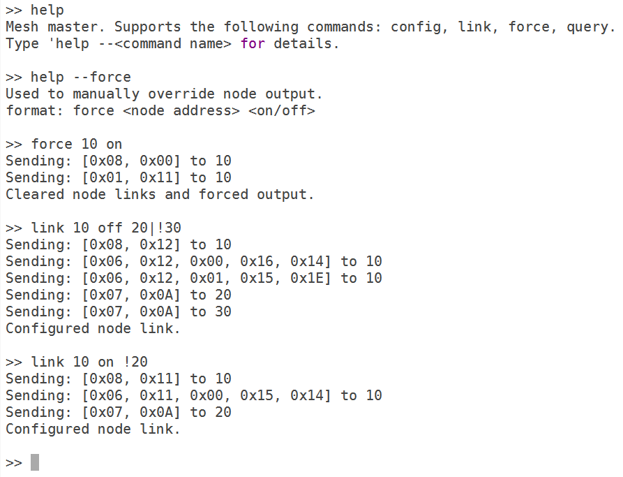 Command Line Interface
User commands are parsed by the master node, and essentially translate to one or more network messages. An exception is help, which is merely used to detail the functionality of every other supported command. A detailed list and explanation of each command is given below.
| Command | Semantics |
|---|---|
| Force | Clears the specified node's output dependencies and forces output on or off. |
| Link | Sets a node's on or off dependencies according to the specified sum of products. |
| Query | Queries a node for an input or parameter value. |
| Config | Configures a node parameter |
| Help | Displays messages to explain the format and usage of other user commands |
Areas for Further Development
While the software we've developed offers a significant amount of customizability, a number of features can be improved on and developed further. In particular, I think the following are great next steps for expanding the scope of this project.
- The user interface is currently implemented over the command line, and is not very easy to understand. An important step towards making this a consumer application would be to develop a thin GUI layer that provides a more friendly interface to the user. In particular, it may be interesting to have the ability to name nodes, so users don't need to remember which node corresponds to which physical device.
- Link logic is currently implemented using sum-of-products, and is limited to a maximum of ten summed products, and ten nodes per sum. This is because we implemented the logical table as a statically allocated array. It may be interesting to use a dynamic data structure to allow more flexibility.
- Nodes currently support only one input and one output. It seems valuable to expand this to a larger number of general purpose terminals per node.
- Several parameters were limited to 2-byte values due to design decisions made early on in the project. It may be worth expanding these to a 4-byte length.