In order to fulfill the requirements of being a lightweight and simple package, the nodes themselves had to be kept to a minimum, and allow users of all knowledge levels to be able to easily interface with them. Due to these constrains, much effort was put into streamlining the nodes for users, both on a hardware and software aspect. However, in this section we will primarily talk about hardware design and optimization.
High Level Design
The nodes used in this project are designed to be easily used by any users such that it is easily and painlessly configured towards any desired state. This is implemented by creating generic input and output connections to the nodes through headers, and provide different modules that contain various components to the user. For example, we can provide a module that allows a user to simply plug and play a photoresistor into and input and a servo motor into an output, and through the applicaiton layer one can easily hook up variable relations across the network. The node is also very low power and inexpensive; this is explained in more detail in the lower level design section.
The node consists of the following key components:
- An nRF24l01 Radio Transciever
- A 3 battery AA power supply
- A PIC32 microcontroller
- A TFT header for debugging purposes
In order to create a fully functional independent node for practical use, several factors had to be considered when designing the nodes. Namely, a node that was too fragile, large, or expensive, or even required too much power would be impossible to implement from a practical standpoint. Due to this, as well as our previous experience from college coursework, we decided to use the PIC32MX250F128b microcontroller as the processor for our nodes. This inexpensive, easy to implement and hard to break chip would allow us to utilize the required libraries and tap into enough processing power to meet our network demands while drawing very low amounts of current.
Speaking of network demands, due to cost and power constraints, we selected the nrf24l01p radio transciever for many of the same reasons as the PIC; that is, the previous experience, available libraries, low power draw, and sufficient reliability.
We also implemented an "alive" LED for a simple power on and working verification for users. The power supply is 3 AA batteries, something that customers could easily replace should the battery die,. Future revisions of the node will include an enclosure with only the battery pack and status LED protruding so that it is less likely to damage the components on the board.
The node was designed to fit on as small of a perfboard as possible. Future iterations could include a printed circuit board if mass produced in order to save costs, but for small scale development perfboards are more inexpensive. The TFT display, although visible on the drawing below, is not included with every node and is merely useful for debugging purposes. This is why it is not costed with any of the nodes themselves.
Node to node communication was achieved by appending a specific ID based on the receiving node and packet type, so that only the node that the data packet was destined for would be read by the destination. This was able to be dynamically changed by the mesh network to support multi-node hops.
Hardware Design
The PIC32 and nRF24L01 require a constant 3.3V power supply, so three 1.5V batteries are fed into a 3.3V regulator to provided a constant power source, since there is about a 1V drop across the voltage reg. This power is fed into the nRF Vin pin, and hooked up to the PIC32 according to this guide. Although we programmed the PIC32's using a microstick, it is very possible to support PICKIT3 programming on the device.
The nRF requires several different pins to fully function. It requires an SPI connection, an interrupt pin, and a connection to Vdd and ground. After hooking these pins correctly the radio functioned as intended. The TFT header was soldered onto the board to provide superior debugging and validation support. By using header pins, only one or two TFTs are necessary to fully debug the board.
The input and output ports were given headers and are hooked up in a Power/Signal/Ground orientation, with the output pins being able to support PWM outputs for the config function. This allows for inputs and outputs to be supported as long as they fit the pinout of the I/O headers, meaning that any possible configuration can be achieved by the hardware.
Besides these considerations, hardware design was fairly trivial besides those considerations made in the high level design discussion. This is because the hardware was designed to be as flexible as possible, leaving as much room as possible for various configurations.
With the minimal hardware on board, the PIC32 drew around 75 mA of current at steady state, enough for 300-400 hours of battery life. However, if further optimizations were made to the radio, and perhaps if the PIC32's power management was better managed, months of battery life could easily be achieved. This is because the nRF radios proved to require heavy micromanagement in terms of dropping packets in the mesh network. If packet reliability could be improved via radio antennas or other hardware, power budget would be significantly less.
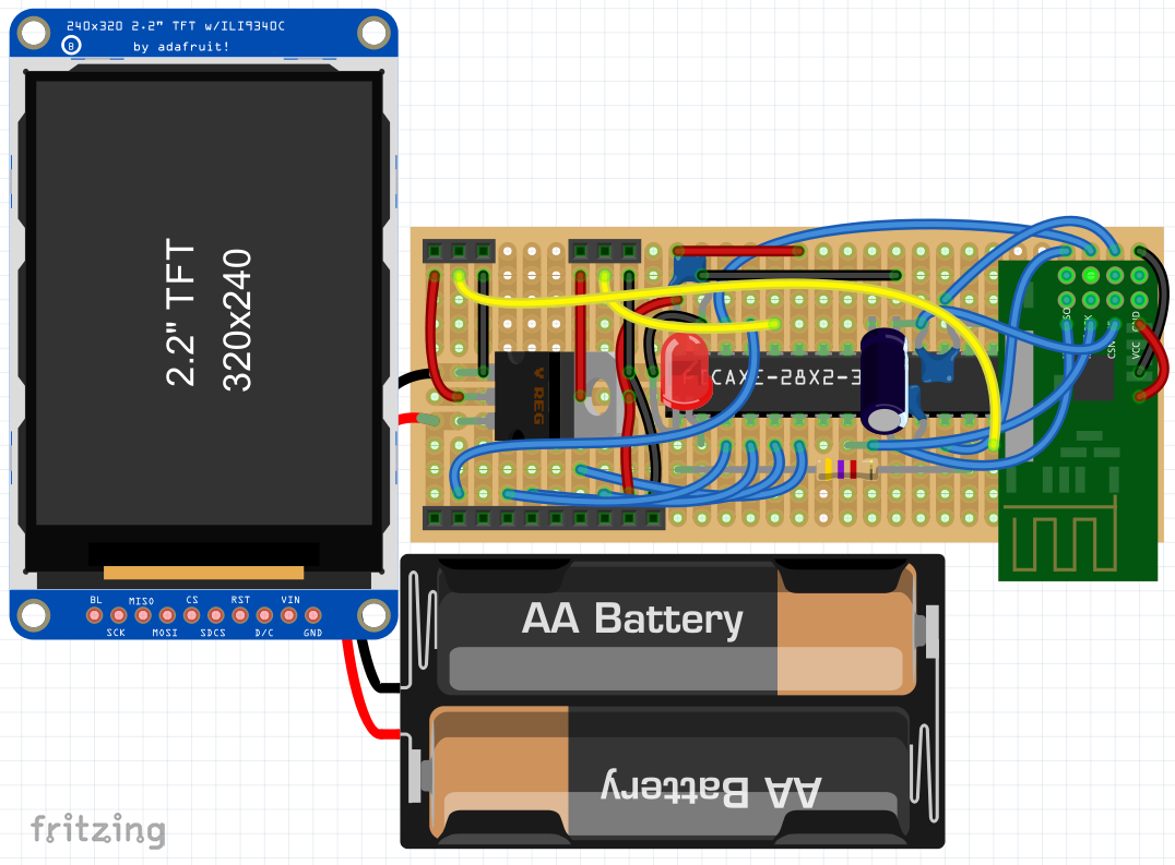 General Node Drawing
Each node except for the master contains a TFT display so that the actual packets going through the networked can be visualized. This is useful for debugging purposes as well as ensuring correct operaiton of various attachments put onto the nodes. The master node, instead of having a TFT display, simply puts its outputs onto the serial terminal that is used to interface with it. This is achieved through a KEDSUM CP2102 USB to UART module. This allows for a user to communicate with all general nodes through a single master node that can be universally plugged into any computer with a USB port. The master node is also equipped with a PIC32 and nRF24L01 so that it supports the same interface as the general nodes.
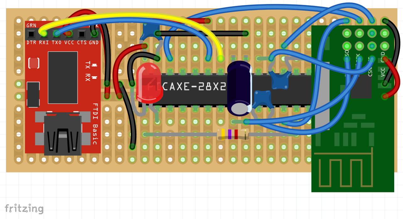 Master Node Drawing
Hardware Optimization
Optimally, each node would be automatically be assigned an ID from the master node upon powerup, and if no master node if available, actively poll the master node every minute searching for it. The master node would be able to keep a list of paths to nodes and not require any nodes to be restarted to connect. Nodes would be in complete enclosures on PCBs, with 2 radios per node, one strictly for receiving and one strictly for transmitting. This would allow for simultaneous transmission and reception of message, which is what is required for extremely large mesh networks.