Introduction
 Musician Simon
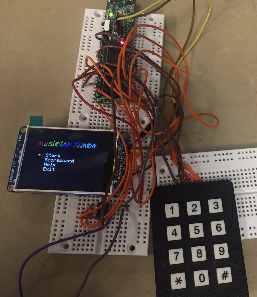
Our project is a simon game based music note player. A 320*240 TFT screen is attached to PIC32 microcontroller to display the game interface. Players need to remember a music note flow gradually and play them in the exact order as it showed on the screen. This will help to train players to learn a music score quickly and have fun with simon game at the same time.
About
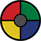
Simon game is an electronic game of memory skill invented by H.Baer and H. Morrison, shown in figure 1. The device has four colored buttons, each producing a particular tone when it is pressed or activated by the device. A round in the game consists of the device lighting up one or more buttons in a random order, after which the player must reproduce that order by pressing the buttons. As the game progresses, the number of buttons to be pressed increases.
Simon Game
We are going to perform numbered music on the keyboard. According to numbered musical notation standard, number 1-7 represent key C(do), D(ré), E(mi), F(fa), G(sol), A(la), B(si). When we pressed a number on the keypad, the speaker will output a corresponding frequency of sound.
Based on Simon game and numbered musical notation introduced above, we came across an idea to combine them together. Firstly, seven colored button will appear on the TFT screen and first round of game, it light up a number randomly. The user should pressed corresponding button on the keypad, which produce a tone. Then, second round will light up two button in a certain order. The user should reproduce the same order through pressing the button on the keypad, producing two tones in order. Each round after that, the button lighted up on TFT will increase by 1 and finally, we get a tone flow which composes a part of great music.
The basic mode introduced above is normal Simon mode we called fast game. There will be other modes such as musician mode. In musician mode, the user can choose a specific tone flow stored in memory to practice and choose difficulty they want to play. A third mode will be record and play-back mode. There will be a microphone attached to the board to record simple music sound from a speaker or humans. Then it will be converted into numbered musical notation and stored in an array to be played back.
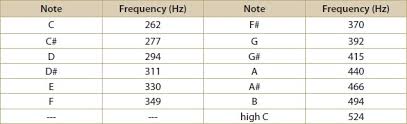
The sound played by the speaker follows the typical musical note frequency standard. If needed, several frequencies may be adjusted for a better user experience.
Music Note Frequency
Design
Software Design
User Interface
We tried to make this a beautiful game which not only makes sound but also displays satisfactory things. We also tried to make it resemble a NES game because it is so classical and we played it a lot. That is one reason why we choose to implement a video game using this microcontroller.
The game title is displayed on the top of each page. We downloaded the specific type of font and made a greyscale image of that title. We loaded the image into matlab and processed it into a pixel array. We added it to the beginning of our code and display it when the TFT display is updated. We also add some calculation to decide what color should each pixel be so that the title becomes more attractive.
There are two game modes: fast game and musician mode. During fast game, the player can skip the difficulty and music setting and start the game directly. The setting should be the default one. While in musician mode, the player will be asked to choose a difficulty and a music from a list to play.
The game contains three levels of difficulty for user to choose. The difficulty is related to the length of the sequence which the player will be asked to repeat. The higher the difficulty, the longer the length.
The music is recorded in the system as a series of notes. The game has three default songs for players to play. The player can also use the record function to add customized sequence to play. When the player repeat the sequence, they feel like playing the piano. That is the difference between the game we design and the classical simon which generates random for user to play.
The game saves the best score for each sequence and each difficulty. When the game is over, present score will be compared to the recorded max score in this game setting. The user will be informed that he has broken the record and he can view it and all the other records in a Scoreboard page.
Scoreboard
Player uses keypad to play this game. Player can press '2' or '4' as 'UP' and '6' or '8' as 'DOWN' to navigate the menu and '5' to decide. In inGame page, the key from '1' to '7' will serve as the keys of a piano and the player should press the keypad following the system's guidance printed on the screen. Several pages don't have any menu list on it which allow user to press any key to continue, such as Scoreboard page.
In Game(auto showing sequence)
Game(TFT) Thread:
This thread updates the TFT display according to the present state variables. Basically, each keypad input would change some of the variables and when this thread is waken up, it updates the screen. Some flags are added for this thread so that only the part which needs to be updated gets updated and the other parts do no changes. This design helps to improve the speed of the program because it minimizes the TFT tasks so that the microcontroller gets more time to do other useful work and more importantly it avoids the screen flashing when the pixels get repaint, because each time we need to fill a black rectangle to 'erase' the previous marks and then draw new marks on the screen.
Three finite state machines are designed here. First one is used to record the state of the progress of the whole program, such as Main Page, Mode select. The second one is used to help the player to record a new music and the last one is used when the player repeats the sequence.
Keypad Thread:
Each time the player presses a key, this thread gets the input and alters the global parameters based on the present state variables and the input. Those various variables are used to determine what the TFT display should display.
DDS Thread:
Used to generate sound when the player repeat the sequence, the sound of a key is associated with the frequency of that music note, for example, the frequency of the sound made when you press key 1 is the frequency of middle C. The code is similar to what we have in lab 2.
Hardware Design
Microphone
The microphone captures the voice signals from the surroundings. The voice signals are then amplified to a certain level using an amplifier circuit. The amplified signal may have both positive and negative cycles. Since the ADC of the microcontroller can read only the positive voltages(-0.3v to 3.3v), the signal output from the amplifier should be clamped above the zero voltage level so that the ADC can read the complete cycle.
Electret Microphone with Amplifier
Hence the voice input part is designed to capture the voice signals and modify them in such a way that the ADC of the microcontroller can read them. The voltage signal coming from the microphone is very small and hence these cannot be read by the microcontroller. Before fed this signal to the microcontroller it should be amplified. In this project a NPN transistor is used to amplify the voice signals to a particular level so that the ADC will be able to read it. The output capacitor can be removed to get some positive bias for output signal which should be in range of -0.3v to 3.3v.
Keypad
Adding a 12 key keypad (0 to 9 with * and #) requires seven i/o pins. Each switch connects one row wire to one column wire. Connection scheme used in the test code is shown below. 300 ohm resistors protect the outputs from short circuits when multiple switches are closed. The 10K pulldown resistors provide an input source when the switches are open. The code displays the button label when a button is pressed, and -1 when no button is pressed. If you add one line of code, you can eliminate the three 10k pulldown resistors by turning on internal pulldowns. The poorly documented CNPDB register (Change Notice Pull-down Enable B) selects input bits to pull down.
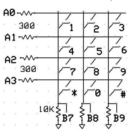
Keypad Connection
Analog to Digital Converter
The PIC32 has a 10-bit ADC which runs up to 1 MHz sample rate, although it is limited to a little more than 500kHz because sampling is controlled by an ISR (Interrupt Service Routine. The ADC_CLK_AUTO is turned on so that conversion immediately follows sample-aqusition, but aquisition is started manually in the ISR and goes into one slot of the buffer array where it is immediately copied into the Vref DAC for output to the scope. The first image shows the signal generator input to AN4 on channel one and the limited resolution Vref DAC on channel two.
The ADC specification (search on TAD in the datasheet) says that for a low Z source (smaller than 500 ohms) the ADC bit-clock period must be greater than 65 nSec and the ADC sample period must be greater than 132 nSec. At peripheral bus clock of 40 MHz (period 25 nSec), ADC_SAMPLE_TIME_6 should work for the sample period (150 nSec) and ADC_CONV_CLK_Tcy2, while a little fast (50 nSec), seems to work for the ADC clock.A safer code turns ADC_AUTO_SAMPLING_ON so that the ADC runs as fast as possible makes it possible to sample at 500 KHz using ADC_CONV_CLK_Tcy, which exceeds the minimum bit-clock period time by setting the bit sample time to 100 nSec. Hooking up a higher quality DAC ( 4116R-R2R-253LF resistor array) gives 8-bit resolution and allows accuracy testing of the ADC. The DAC resistor array is mapped to port B bits (lsb) 0-5 and bits 14 and 15 (msb). These port signals are pins (from lsb to msb) 4,5,6,7,11,14,25,26. The mapping does not use port B, bit-6 because the 28 pin PDIP package does not support it (see datasheet Table 1.1). Some care is needed to prevent the digital signals from coupling to the analog output. The second image shows the output from the 8-bit DAC on the bottom trace with small coupling artifacts near the 50% point.
Direct Digital Synthesis
The output sound are sine wave signal generated by using Direct Digital Synthesis(DDS) technique on one channel of the external DAC through SPI. The DDS unit has a sine wave table of 256 entries, which cost 8 bits. The increment step is calculated by the frequency assigned by users. An example can be seen in DSP page.
Result & Future Improvement
Results
The first page is the game main menu. There are four options. 'Start' will start a game and jump to mode select. 'Scoreboard' will show score records for each song and each difficulty. 'Help' is the text tutorial about how to play the game. 'Exit' will re-enter the game for now.
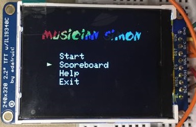
Start
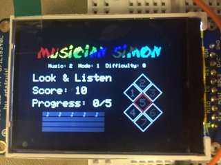
The InGame page is more complex. There are two different states. First one is auto showing the note sequence. The specific note will be highlighted red on the right side of the screen. The second one is user typing and repeating the same sequence. There are small music note symbols on left-bottom side of the screen corresponding to the game progress. If the player pressed one correct number, one symbol will change color from grey to green.
In Game(auto showing sequence)

In Game(usering typing)
If the player presses the wrong button, the game is over and the score will be showed on the score page. Players can choose to play again with the same music and same difficulty. Or choose 'mode' to select a new music sequence and difficulty. 'Main' will return back to the first page.
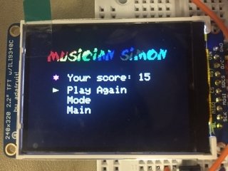
Game Over
If the player gets a better score under the same song and same difficulty, a new record page will show up. 'Continue' will take the player back to main menu.
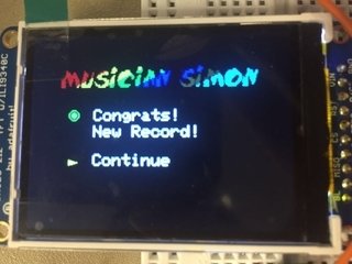
New Record
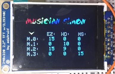
The scoreboard page stores best scores for each song and its corresponding difficulty.
Scoreboard
The record page is designed for game improvement. A record-play can be added to use this page.
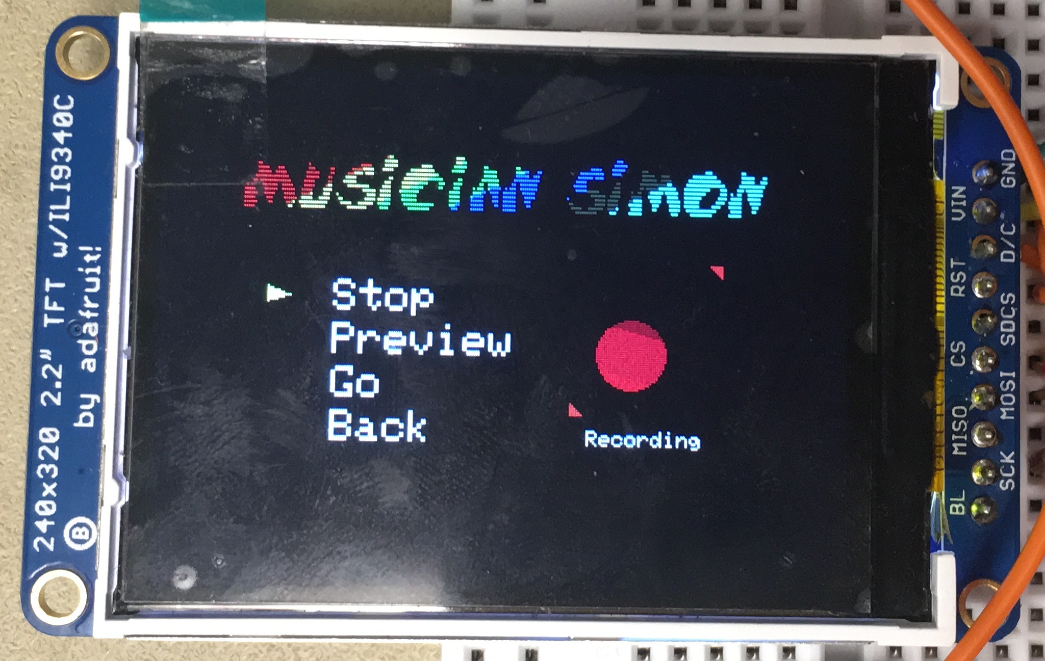
Recording
Future Improvement
For future improvement, there are lots of things we can do. First, we can add record-play mode to allow players to type the note sequence or receive from microphone and save it for them to play. Then, we can make our own keypad using small buttons in the lab to make it more similar to the keypad display on the screen. Next, we can add FM sound synthesis to make the output sound more string-like and more pleasant.
Appendix
The group approves this report for inclusion on the course website.
Finite State Machine for User Interface
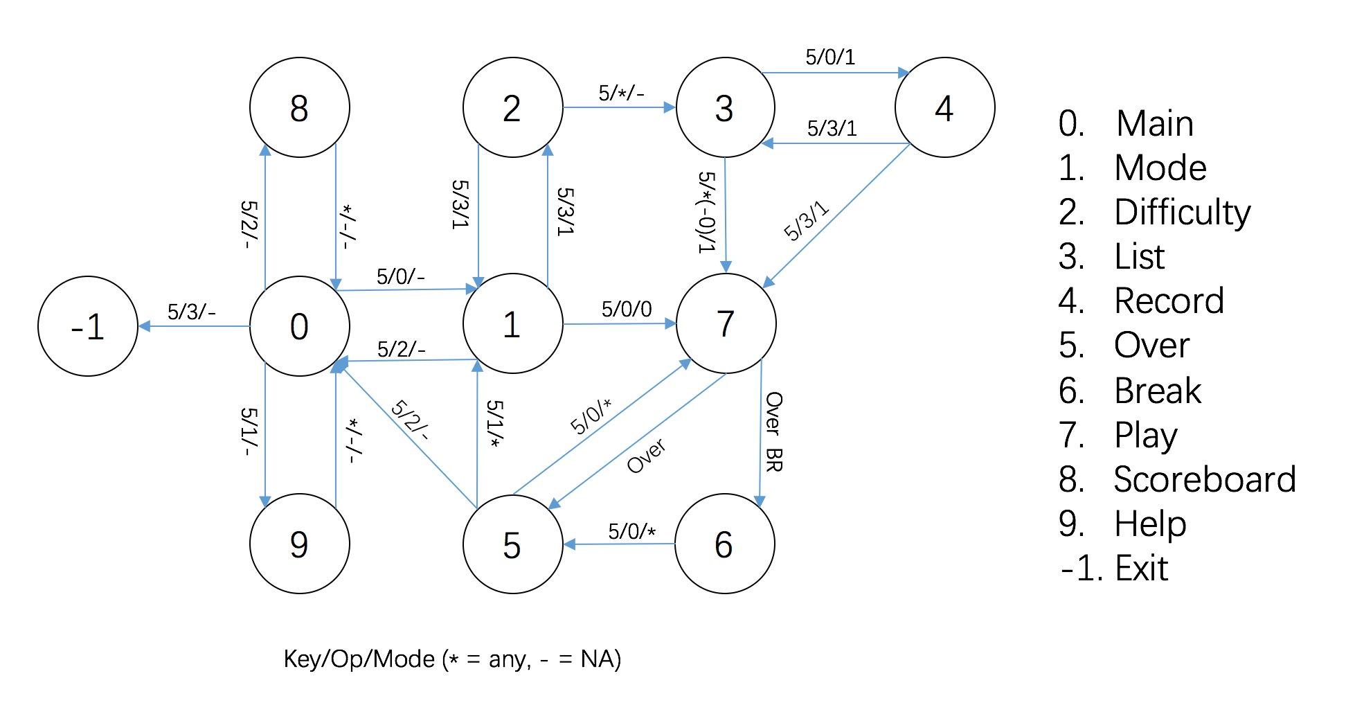
Table of Cost
| Name |
Unit Price |
Quantity |
Total Price |
| PIC32MX250F128B |
$5.00 |
1 |
$5.00 |
| MicroStickII |
$10.00 |
1 |
$10.00 |
| White board |
$3.00 |
2 |
$6.00 |
| TFT LCD |
$10.00 |
1 |
$10.00 |
| Lab speakers |
$2.00 |
1 |
$2.00 |
| MCP4822 |
$3.00 |
1 |
$3.00 |
| Resistors |
$0.10 |
7 |
$0.70 |
| Lab keypad |
$5.00 |
1 |
$5.00 |
|
41.70 |
References
Work Load Breakdown
- Hui Xu: Software development, game interface design and display, hardware+software debugging, and final report.
- Xiaobin Li: Hardware development, microphone setup, webpage development, hardware+software debugging, and final report.
Contact Information
Hui Xu: hx93@cornell.edu
Xiaobin Li: xl572@cornell.edu