The project’s focus is to accurately simulate the movement of a human arm on a small-sized robotic arm, such as aiming and throwing small objects, i.e. a ping pong ball. We use motion-controlled, 3-DoF robotic arm that takes the user’s throwing motion as a reference to its own throw. A robotic arm that mimics the user’s arm motion has many different applications. One can use the robot arm to lift heavy objects that human arm can’t handle, or one can use the robotic arm remotely from distance. In order to incorporate both mechanical and electrical components, we intended to control a beer-pong catapult robot that simulates the user’s throwing gesture. A mini-scale beer pong game can now be played by a robotic arm that throws the ping pong ball for you. Play beer-pong in style and add extra entertainment to the system.
A video showing of the final project can be found here:
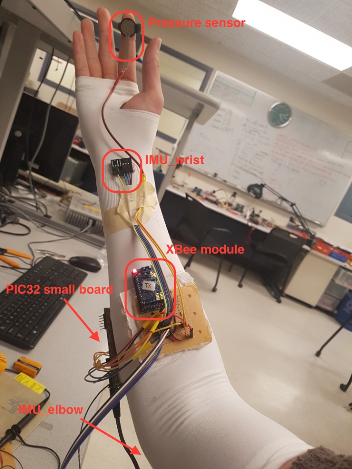
User interface for our device is strictly through a hand-motion gesture control. The aiming of the catapult and strength of its throw is determined by the computation done with accelerometers attached to the controller device. The controller device is in a form of an arm sleeve that consists of two IMUs. User needs to press on the pressure sensor to start the complete simulation of the arm's movement. This is when the user is expected to aim and then as soon as the pressure sensor is released there will be a fast movement forward that will throw the ball, similar to what a catapult would do. For maximum enjoyment the user is encouraged to make the throwing movement after the pressure sensor has been released. This won't affect the throw, but it will make it seem more like the user is also controlling the throw.
Additionally the controller can communicate to the robotic arm wirelessly by having all of the sensors located on the arm hooked up to a local PIC32 which will send signals via an RF transmitter. On the robotic arm we will have an RF receiver which will receive the signals from the controller and move the robotic arm accordingly in real-time.
The PIC32 on the robotic arm extracts angles from three different axes in the arm motion. The arm controller uses readings from the IMU which delivers two angles from the elbow, and one angle from the wrist. Using a combination of gyroscopes and accelerometers attached on elbow and wrist, the controller sends out its current angle from the calibrated zero. The pressure sensor is attached to the index finger to detect when the ball is held and released from the hand of the user. The robotic arm then mimics the user’s movements to try to throw the ball at the position that the user attempted to hit. The joints of the robot are driven by servo motors, which provides enough torque to throw small objects like ping pong balls.
Additionally the controller can communicate to the robotic arm wirelessly (RF) by having all of the sensors located on the arm hooked up to a local PIC32 which will send signals via an XBee. On the robotic arm we have an other XBee which will receive the signals from the controller and move the robotic arm accordingly in real-time. We will discuss this setup more in depth in the "things that didn't work" section, because although we got it to work, it wasn't as reliable as wired UART communications.
The project was divided into 2 different big sections: the controller and the robotic arm.
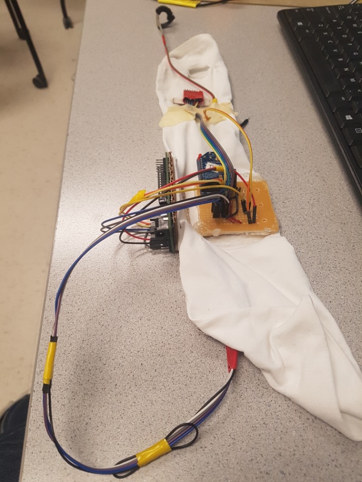
The controller consisted of:

	1) PIC32 small development board
	2) x2 IMUs (MPU6050 Accelerometer Gyroscope Module 6 DOF 6-axis)
	3) Pressure sensor used (variable resistor)
	4) XBee RF module (transmitter)
	5) All of the components were attached to a sleeve as seen in the picture below
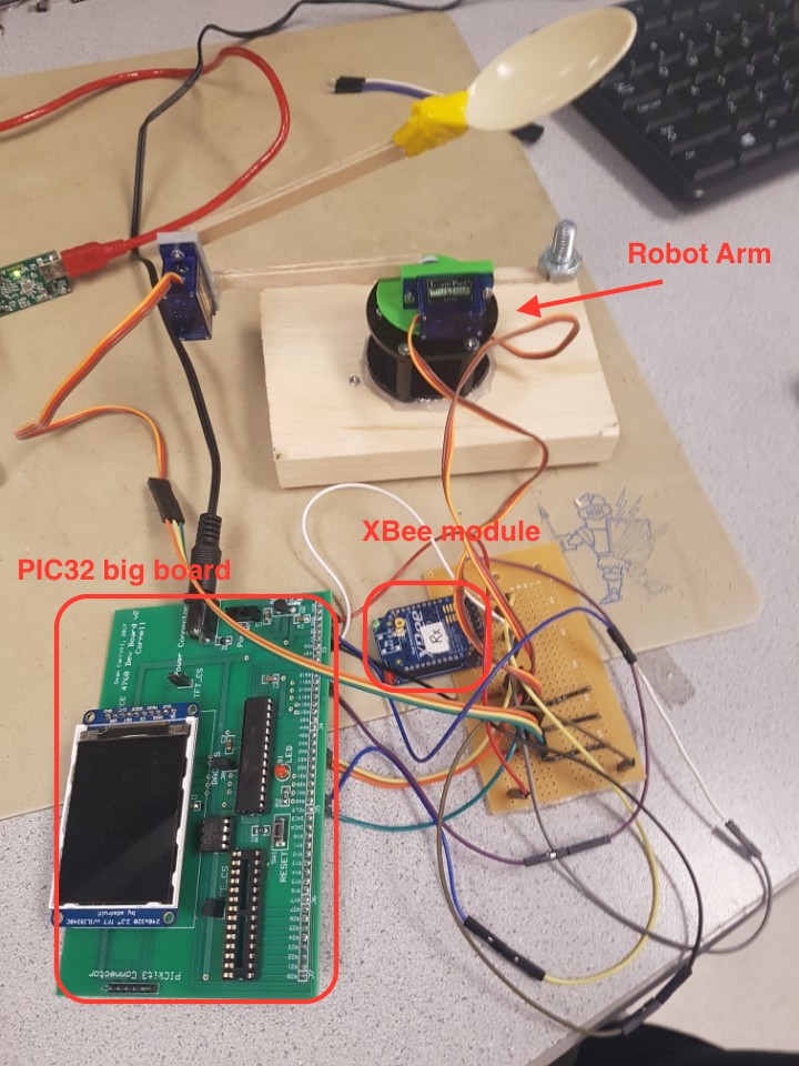
The robotic arm consisted of:

	1) PIC32 big development board
	2) 3 servo motors
	3) XBee RF module (receiver)
All of the controller hardware is on a sleeve that the user has to put on for the project to work.
The IMUs were located on the elbow and on the wrist. This allows us to extract 3 different pieces of information:
Rotation from the shoulder about vertical axis. (from IMU on elbow) Rotation from the shoulder about horizontal axis. (from IMU on elbow) Rotation from the elbow about horizontal axis. (from IMU on wrist)
The controller comprises of several main components. As you can see in the figure below, everything on the controller is run on the PIC32 small development board. We use a small dev board (which can be found here) to wire up the IMU, pressure sensor, and XBee module. Two IMU’s are wired to the board, and are each attached on wrist and elbow. The pressure sensor is wrapped around the user’s index finger by velcro. The XBee is in the middle of the forearm to our board handling all connections. All of these components are attached the the white sleeve that acts as a motion-controller.
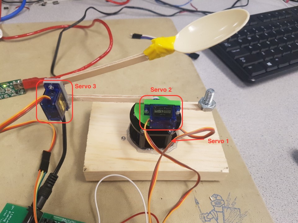
Due to time and budget constraint, our robotic arm isn’t the most sophisticated looking system. However, it behaves just as we had intended and serves its purpose. The system requires three servos to translate the IMU readings to motion in different axes. As shown below, we give constraints to each servo so that we don’t surpass the angle of its physical limitations. Servo 1 rotates approximately 180 degrees, and the other servo 2 and servo 3 rotates 40 degrees and 90 degrees respectively.
Servo 1 that rotates the base is fitted into a casing that is laser-cut to minimize jittering. Later we decided that the base casing should also be attached to a plank of wood for greater stability, since the arms should have imbalance in center of gravity. Then servo 2 is screwed into a 3D-printed mold that fits right into servo 1. The arms of the robots are extended by birchwood sticks. Finally the holder or bowl of the ball is made out of plastic spoon.
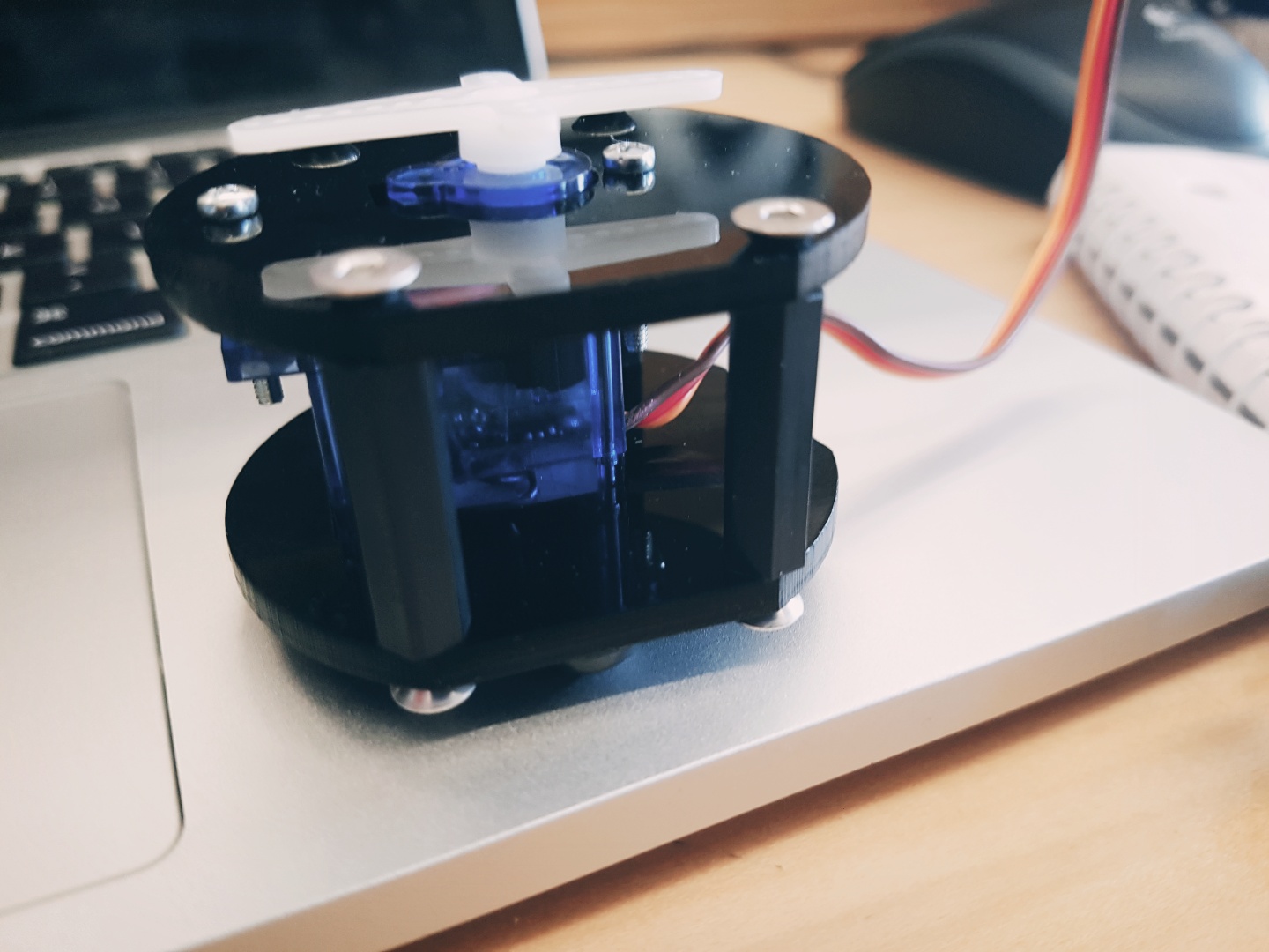
The “shoulder joint” is replicated by servo1 and servo 2. The elbow movement is replicated by servo 3 which is attached at the end of the stick extended from servo 2. The servos are then connected to a board which is then connected to the PIC32 on a big development board.
The two XBee modules communicated to each other via UART. We used the default pins setup and UART relevant codes on protothread header, “pt_cornell_1_2_1.h”. On big development board the U2RX is assigned to pin RPA1 and U2TX is assigned to pin RPB10. On small development board the U2RX is assigned to pin RPB11 and U2TX is assigned to pin RPB10.
We communicate to the IMU’s using Inter-Integrated Circuit (I2C) communication protocol. Both IMUs use the channel to communicate via I2C, and using the address bit (low or high), we distinguish each IMU and receive data from the desired IMU. Pinouts RPB8(SCL) and RPB9(SDA) is used for I2C communication with IMU’s.
We utilized a I2C relevant header file,“i2c_helper.h”, from past project called “Self-balancing Robot” that also used IMUs, you can see the project here:
http://people.ece.cornell.edu/land/courses/ece4760/FinalProjects/f2015/dc686_nn233_hz263/final_project_webpage_v2/dc686_nn233_hz263/index.htmlThis was done using Analog to Digital Converter and calibrating a threshold resistance so we can have two states of PRESS or NO PRESS. The pressure sensor is connected to pinout RPB13 on small development board.
Our interaction with servos was sending pulse width modulation signals. We did this by setting the Output Compare pins to their PWM mode. We set up three Output Compare pins for the three servos. Servo 1 is receives signal from pin RPA3 (OC3), servo 2 from RPA2 (OC4), and servo 3 from RPA0 (OC1).
Most of the math we used was very simple calculations to convert data from the IMU to PWM signals. The main complication that arose was that our IMUs would drift after moving it in a certain direction and back. From recommendation from Professor Land and exploring previous projects using similar IMU data processing, we decided to do a quick approximation based on two principles: when IMU is still the gyroscope data will drift and when the IMU is moving accelerometer data is not very accurate.
The IMU’s provide angular velocity of different axes. Though the IMU’s support 3-DoF of angular velocities, we only use two from the elbow and one from the wrist. “Tiltz_elbow” specifically stores angle value derived from integrating the angular velocities about z-axis (vertical axis) every dt equal to 0.001s. Though there seems to be drifting after rotating around in wide ranges, we neglect the drifting particularly for this measurement because the actual angle range required for aiming at cups is relatively narrow and does not induce drifting as much. “Tilty_elbow” and “Tiltz_wrist” uses combination of the tangent of accelerometer data on the other two complementary axes and the integrated gyroscope data. Then, the two data is computed together by a weight sum of 2% accelerometer data + 98% gyroscope data. So for instance, “Tiltz_wrist” will have 2% component from tangent of accelerometer reading about x and y added to 98% component of the integrated gyroscope data (which is ultimately angle). While some teams decided to implement some kind of kalman filter to avoid drift, we were only concerned with angular movements which led us to focus on the gyroscope data. The actual computation code can be found in the Appendices.
There are two distinct pieces of software that we had to write for our project. One for the PIC32 on the Big Board, which was the one controlling the robotic arm, and another one for the PIC32 on the small board which was the controller.
Communication between the PIC32 and 2 IMUs
The IMUs we use in this project is MPU6050 model, which uses i2c protocol for communication with the host device. PIC32 has capability of two i2c channels, however we only utilize one because MPU6050 has a device address, 0 or 1, which is used for talking to the specific IMU unit.
Most of the code for communicating with IMU’s are written in i2c_helper.h, where read and write functions can be found. Setup for IMU’s are written in main, where we wake up and specify sensitivity of the IMU’s.
Pressure Sensor
We use ADC module to read voltage values from the pressure sensor to detect whether the user wants to control the arm or to release and throw the object resting on end of the arm.
Communication between the two PIC32: UART
There were some example codes to support UART in “pt_cornell_1_2_1.h”, however we modified a good amount of these for our application.
In small board, we modify the terminator character to be ‘~’, and remove echoing functionality that was meant for serial communication with a computer. The modified code can be seen on the appendix.
For big development board, we only use the initialization code and add interrupt functionality. Since the big board does not run any other threads other than the thread that keeps changing the pwm values, this method works great. When the receive interrupt is fired, our handler stores all the received character in order until it detects the terminator character, at which it stores 0 into the corresponding index of storing variable instead of the terminator character to indicate the end of the string.
Servo motor control
Servo motor control code is all written in the big board under the thread, protothread_pwmSet. The serial data received from ISR is parsed into four variables: tiltz_elbow, tilty_elbow, tiltz_wrist, PSensor. The first three are used to calculate the pulse width we need to send to each of the three servo motors, and PSensor value is used to check whether we want to control the second link or not. This value essentially works as a release mechanism.
One of the things that we were trying to include in our project was a holding device that would mimic the functionality of fingers. However we failed to accurately approximate how long it would take us to finish the project without that. Our final prototype does not have a holding and releasing mechanism, and rather has a spoon that bowls the object to be thrown. It would have increased complications in hardware implementations, and induce mechanical instability to the robotic arm because of the added weight on the upper portion. Hence, we decided to neglect it at the end to appropriately schedule out the project progress. Our current design of the robotic arm works more like a 3-DoF robotic catapult.
We spend most of our effort and time debugging UART and RF transmitters, which we later discovered that there were soldering issues on our small development board. By testing with the oscilloscope, the UART communication via wire connection was found to have no problem after the quick soldering fix. However, using XBee’s to transmit and receive data without buffering and bursts of data required reconfiguring settings on XBee modules themselves.
Another problem that we had was grounding issue with the PIC32 boards. We found that when the boards are initially booted up, they have to be connected with the microstick II, or grounded with power supply. This issue has been observed by many other groups in the lab as well.
Our final demo was done without wireless communication between XBees because the XBee communication turned out to be a little unreliable if we wanted to keep using the system for more than 30 seconds. For this, we decided to show the demo connecting both PIC32s via UART directly with wires.
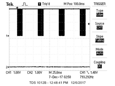
Figure above confirms the rate of UART transmission at 65ms
We performed sets of testing to deduce numerical specifications for our system. Drift tests were done for each servo to experimentally observe drift in angles. Also, load test was performed to see how much weight the system can handle to throw off the spoon/ bowl without overloading the static torque from the servos. Finally, we tested the range of throw to specify the shortest and longest distance the throw can cover.
Speed of execution is also an important factor as a specification of the system. These specification tests are also correlated with the usability discussed in the next section.
IMU drifting test:
Base rotation (IMU on elbow) - 20 cycles of change in 120 degrees range about vertical axis of the shoulder resulted in approximately 8 degrees angle drift. (negligible for smaller range of motion)
Arm 1 rotation (IMU on elbow) - 20 cycles of change in 40 degrees range about horizontal axis of the shoulder resulted in no drift. (weighted sum of gyroscope and accelerometer data appropriately corrects the drift)
Arm 2 rotation (IMU on wrist) - 20 cycles of change in 90 degrees range about horizontal axis of the elbow resulted in no drift. (weighted sum of gyroscope and accelerometer data appropriately corrects the drift)
* While testing the arm 1 and arm 2 rotation, we noticed that the base servo was slightly rotating as well. This may be due to IMU’s position on the elbow that isn’t securely fixed at one position. The arm movement makes the sleeve elastically extend and contract, and in this process, the IMU may be effectively moving around. This may also cause movement to the base rotation and stacking up drift angles.
Load test:
The load test was simply done by adding weight on the bowl to see how much load is acceptable for the system to bear without collapsing and to throw. We empirically discovered that any load less than 150g may be acceptable for functional throwing.
Speed of Execution:
Because of what we believe to be hardware constraints with the XBee’s we were only able to send a signals from the controller to the robotic arm every 200ms. This means that the servo’s position signal is updated every 200 ms. This made the robotic arm seem a little shaky and unresponsive sometimes. For the demo, we directly connected UART pins between the two boards to establish stable and fast communication at the rate of 65ms, which showed smooth control of the robotic arm.
Anyone with arms is able to use our controller as long as they adjust the IMUs to match the location of the elbow and the wrist. However, since the position of different components on the sleeve is located based on arm length of a male user, female users may find the arm controller to be slightly longer. Also, the robotic arm is quite fragile as they are made by birchwood sticks and cheap generic servos that seem to slightly jitter in motion. The robustness of the robotic arm can be improved by replacing the birchwood sticks with 3D-printed parts and using reliable servos. The arm controller on the sleeve can also be improved in terms of robustness by strapping components tighter on the user’s arm. Lastly, the user must acknowledge and consider the slight drifting on the base rotation of the robot and the maximum load the system can take to throw.
We expected most components to be easier to work with. Although we got most of the components working individually fairly early (except for UART), once we started assembling individual components, we faced difficulties in integrating and building dependency between each other. The biggest challenge was to wirelessly communicate the two development boards, continuously sending and receiving IMU data as mentioned previously.
A critical mistake we made in the process of building the system was debugging software after soldering ever circuitry on our final prototype. Setting up all the necessary circuitry on a breadboard and verifying that the software complies with our intentions would have been more time efficient and a better approach overall.
Nonetheless, the final outcome of our project is successful since our expectations were met with the results. The robotic arm does mimic the motion of the controller in real-time and is capable of throwing ping pong balls. We had expected that the wireless communication between the two PIC32’s may take greater portion of our schedule compared to the IMU setup, but we successfully demonstrated a working prototype in the end, not as reliable as wired communication, but working nonetheless. Our prototype should be further studied and improved upon for different applications that require real-time motion simulation such as in the fields of robotics.
At first we divided things up so that everyone would work on a specific component but as weeks passed we realized that we would be more productive if we were at least working in pairs. Once a component was working, we would all focus on get the other one working, but roughly speaking this is a breakdown of how we intended to distribute the work at the begining.
	I2C for IMUs
	Interpret IMU data
	UART and RF
	Pressure Sensor
	Servos
	3D printed pieces
But as mentioned before, it would be more accurate to say that everyone helped each other on each one of the tasks
Our design was built considering all relevant ethical implications. It is a safe design, where all of the components interacting closely with humans (our controller) operate at a low voltage (3.3v). Our system can also be expanded to help people with disabilities like having weak muscles to operate systems that require a significant amout of force, provided with better servos. Overall it is a friendly system that provides no significant risk to the user.
This design also allows the community to be aware of how possible it is to have motion tracking systems for a relatively cheap cost. We don't think this was a thing people were that awere of. The functionality of our project itself is not revolutionary but the concept and the posibilities that it implies can provide great insights to our community on how to provide systems that could potentially help in automating and assiting in difficult tasks.
We were also using low torque servos so on the robotic arm side there weren't also many risks of the servo causing a sudden movement and hurting anyone. Our robotic arm was also built of light objects and had no sharp edges so safety should not be a concern for anyone interacting around the robotic arm.
In terms of legal considerations all Digi International products seem to follow most legal guidelines. Our XBees are compliant for the FCC considerations which is all that matters for uses within a reasonable distance. In addition, the project we presented in the demo did not use wireless communication anyway because it wasn't as reliable as wired UART communication, so the FCC shouldn't be much of a problem. There aren't any immediate potential legal restrictions that would limit the design of our project since it is a very self-contained system.
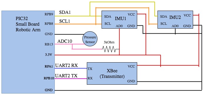
Image above shows pinout of controller.
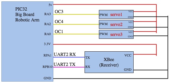
Image above shows pinout of robotic arm.
Class Website
http://people.ece.cornell.edu/land/courses/ece4760/Self-balancing Robot (2015 Final Project):
http://people.ece.cornell.edu/land/courses/ece4760/FinalProjects/f2015/dc686_nn233_hz263/final_project_webpage_v2/dc686_nn233_hz263/index.htmlWe used their i2c_helper.h file to implement our own I2C communication system here
Hyun Dong Chang hc466@cornell.edu
Justin Choi jc2367@cornell.edu
Daniel Fayad dhf63@cornell.edu