|
Hardware
Design
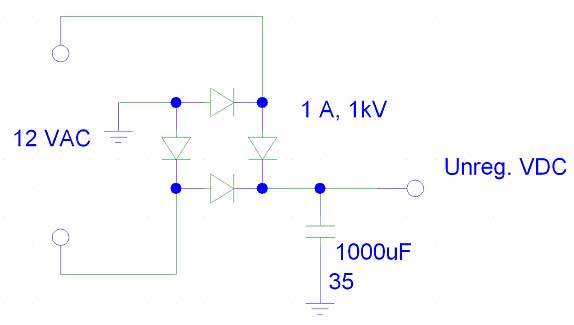
Figure 1:
Full
Wave
Bridge
Rectifier—Main Power Source
Every circuit begins with the power source.
In our CLUB Light, we had a conveniently available transformer
that stepped the line voltage (120 VAC) to 12 VAC.
This voltage was fed into a full wave bridge rectifier, and a 100
mF
polarized capacitor was used to minimize the unregulated output voltage.
From this point, all necessary regulated voltages were created
using voltage regulators.
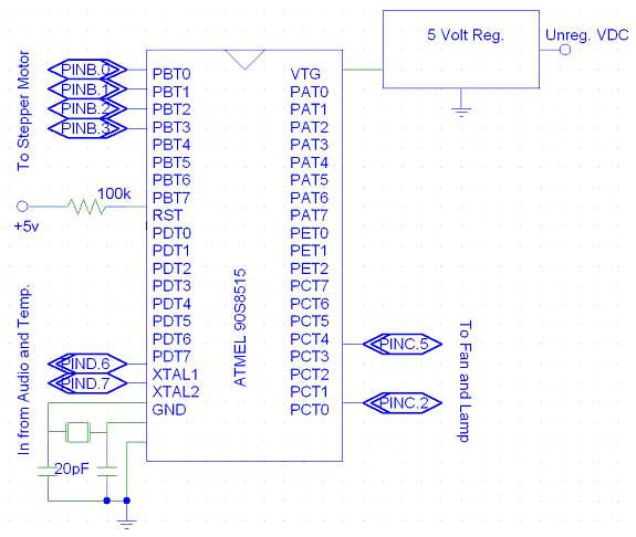
Figure 2:
The
Atmel 90S8515 Microcontroller Unit and its associated ports
A single 5-volt
regulator was used to power the MCU alone, for fear of mixing digital
noise into the analog interfacing circuits.
Additionally, all outputs and inputs were buffered from the
analog circuits to minimize noise.
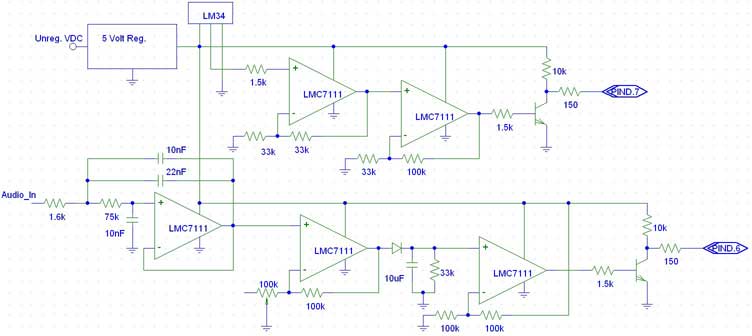
Figure
3: The Temperature Sensor
(top half) and Beat Detector (bottom half)
The heart of the temperature sensor is the LM34
temperature sensor. It
provides a linear output voltage of 10 mV/°F.
The output voltage from the LM34 is then gained by a factor of 2
using the leftmost, top opamp in a non-inverting configuration.
The opamp immediately following it is used as a comparator, with
the trigger voltage set at a temperature corresponding to about 90°F
(keeping in mind the gain of 2 from the previous stage).
When the temperature of the sensor exceeds 90°F,
the output of the comparator goes high (+5 volts).
Finally, this signal is sent into a 2N3904 transistor, which
pulls the pin voltage on PIND.7 low when the temperature exceeds
90°F,
instructing the MCU to turn on the cooling fan.
The audio input receives a line-level input
(typically 2 Volts peak). The
very first opamp is a Sallen-Key 2nd order
Butterworth
Low
Pass
filter with cutoff of about 250 Hz.
This filter was used for its nice attenuation characteristics.
The output of the filter (only the positive excursions of the
audio signal) is then fed into the second opamp that gives a gain of 2,
and its output is passed through a diode.
The capacitor in parallel with the resistor to ground acts as a
filter, increasing the amount of time it takes for the voltage to decay
on the input of the third opamp, a comparator.
The comparator is set to trigger at 2.5 volts, and its output is
again fed into a 2N3904 transistor to interface it to PIND.6 of the MCU
(admittedly, a Schmitt Trigger would probably work better here, with a
rising edge trigger of 4 volts, and a falling edge trigger of 1 volt or
less). The MCU then polls
for a random number (using software) and changes the color wheel
accordingly.
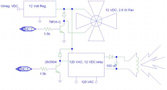
Figure 4: Fan
and lamp driver interface circuits
The fan and lamp driver interface circuits are
simply used to easily control these devices and to isolate the MCU from
high voltages. When a high
voltage is output onto PINC.2, the TIP31-C will sink current and the fan
will turn. The TIP31-C
isolates the MCU from back EMF induced by the stators in the fan motor.
A 12-volt DC voltage regulator supplies the power to the fan.
Similarly, a 2N3904 controls the relay, which turns the lamp on
or off. A smaller transistor
could be used for the lamp relay because a large sink current was not
required.
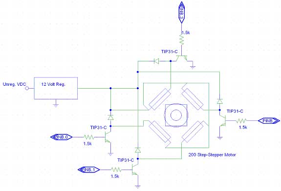
Figure 5: Motor
driver interface circuit
The motor driver interface circuit is very similar
to the fan driver interface circuit.
A 12-volt voltage regulator provides the power to run the stepper
motor (it draws 200 mA of current, continuously).
The TIP31-C is capable of providing the required current to the
stator windings, and additionally, they isolate the MCU from back EMF.
It should be noted that at all times the light is on, this
circuit draws power, which it uses to lock the axle in place when the
color wheel is not spinning. The
motor spins by receiving signals from the MCU.
For example, in order to make the motor spin clockwise as seen in
the schematic above, the ports would have to be successively pulsed in a
periodic sequence: turn on
PINB.3 for 5 msec then turn it off, turn on PINB.2 for 5 msec then turn
it off, turn on PINB.1 for 5 sec then turn it off, turn on PINB.0 for 5
msec, then turn it off, turn on PINB.3 for 5 msec then turn it off….
Every time a period is cycled (from PINB.3 to PINB.0) the motor
turns 1/5 of the distance to the next color.
Hence, five periods are required to rotate the stepper motor to
the next color from the previous color.
The same sequence, but in reverse order, is used to spin the
motor counter-clockwise.
|