
By: Alex Cerruti and Chris Wherry
EE476 -- Spring 2002
PICTURES
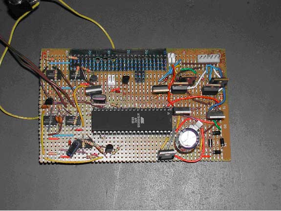
The protoboard that was built to house
the MCU and its analog interfacing circuits.
The stepper motor attaches on the six pin connector at top right,
along with the analog interfacing. The
fan plugs in using the two-pin connector just to the left of the stepper
motor connector. Finally,
the lamp control plugs in at the middle-top portion of the board.
12 VAC is supplied just above the large capacitor in the lower
right corner. The
temperature sensing circuitry is in the top-left hand corner, and the
audio signal is processed in the bottom-left corner.
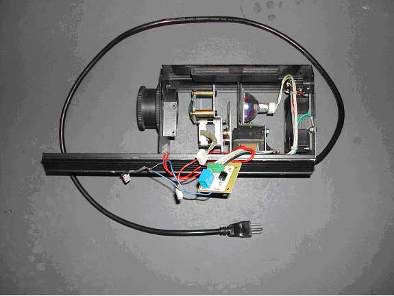
The overall gutted light.
Note that the large blue cube in the center of the image is the
relay used to turn on the light. 120
VAC is supplied to the board via the green connector.
The 120 VAC to 12 VAC transformer is just below lamp, and the
stepper motor is just above the blue relay.
The muffin fan is on the right side of the unit.
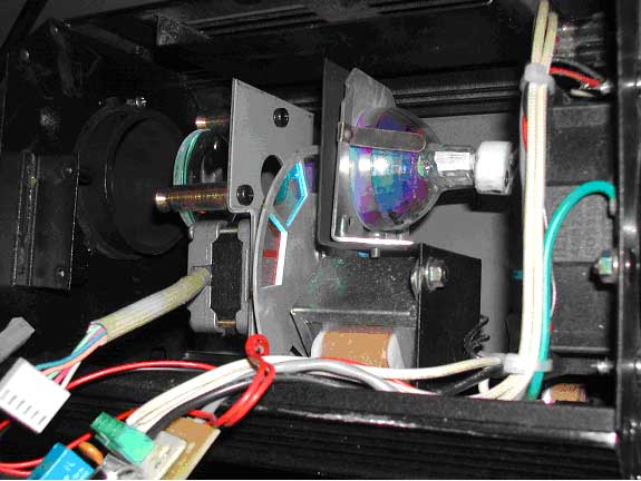
A close up of the transformer, lamp,
stepper motor. Note the
color wheel between the lamp and the stepper motor.