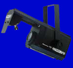
By: Alex Cerruti and Chris Wherry
EE476 -- Spring 2002

High-Level
Design
Certainly
the most difficult portion of the project to implement was detection of
the beats. Rather than relay
on an ADC and complicated algorithms to calculate the beats within the
MCU (using software), we opted for an analog approach.
The analog approach simply takes a mono line-level music signal;
low pass filters it, and does beat detection.
The output of the beat detection is passed to the MCU and is
assumed to be the beats of the music (for more explanation, see Beat
Detection below).
After beat detection, a randomizer was created
using software. timer0 was
polled every time a beat was detected, and the current timer value was
divided out by 11 and the remainder (0 to 10) was used to determine the
position for the next color (since ten colors are possible using our
color wheel). This scheme
offered an easy way to randomize the colors.
CPU
We decided to use an ATMEL 90s8515 processor
instead of the 8051C or the Mega 163 series.
The 90s8515 offered better speed (8 MHz) than the Mega (4 MHz)
and more processing power than the 8051C.
Also, this was the chip that we felt most comfortable programming
with. It also turned out
that the extra instruction space was not a factor in choosing our MCU
because our final line count was around 250 lines!
Furthermore, since all the interfacing was done using analog
circuitry, no ADC’s were required.
Hence, the 90s8515 was the most logical choice.
Stepper
Motor (Hardware)
We built the control interface circuits to run the
10-position color wheel, which is controlled by a 200-step unipolar
stepper motor.
Stepper
Motor (Software)
The microchip also had to be coded to properly turn
the stepper motors. Initially,
upon power-up, the stepper motor (when facing the front of the light)
has to be rotated fully clockwise until the stop-pins hit.
This is absolutely required upon each power up because the
microchip needs to know the initial color (black).
To go to the next color (white) the stepper motor must transition
counter-clockwise through 20 stops.
Each successive color is 20 stops further than the previous.
However, one cannot exceed 200 stops (ten colors) or the
reference point is lost. Hence,
knowing the initial position at startup, and keeping track of the
current position, and the next position, the microcontroller can easily
instruct the motor to turn the required number of stops to the next
color (number of stops to turn = current_position-next_position, where
the sign (±)
indicates the direction to turn).
Buffers
All components that ran off of 12 volts (the
stepper motor, muffin fan, and control lines for the lamp relay) were
buffered from the main processor using TIP31-C’s.
This offered several advantages.
The TIP31-C can sink up to 1 Amp of current, which is more than
enough to run each of the components.
Additionally, the TIP31-C will provide a fairly good buffer to
protect the ports on the microchip from the EMF spikes created by
inductive loads (like the motors).
Cooling
System
Another component that we felt needed upgrading was
the muffin fan. The muffin
fan was directly wired; hence it was always on when AC power was
supplied. We felt that this
was unnecessary, and would make the light cooler (pun intended) if we
used an IC to detect the temperature and have the fan turn on once the
internal temperature exceeded a certain point.
Not only this saves power consumption on the long run, but it
also flexes our analog interfacing skills.
Instead of using an ADC to convert the voltages put out by the
temperature sensor, we simply set a comparator to trigger at a voltage
point that coincided to a temperature of 100°F
(roughly).
Beat
Detection
The original circuit used a capacitive microphone to detect the beats of the music emanating from the speakers. However, the microphones were incredibly sensitive and had no gain control. Hence, in moderately loud environments, the lights would simply lock up and turn off. Rather than detect a beat using logic and software, we took an analog circuit approach. The main reasoning behind this is that these club lights are generally used in conjunction with dance music. Dance music usually has a very distinct low frequency, high amplitude beat. Hence, one could easily detect a beat by low-pass filtering the left (mono) line voltage off of a CD player and passing the low-passed signal into a peak detector. Hence, every time a peak is detected, it is directly correlated with a beat. This is the signal that is then detected by the MCU. Every millisecond, the MCU would poll the port and determine if it was high. If the port was in fact high (signaling a beat), the MCU would send the appropriate signals to change the color.
The original light seemed to be stuck in certain
patterns, always choosing the same colors.
In our software, we decided that we would implement the colors
randomly. To generate a
random number we would poll timer 0 and then take modulo 11 of the
resulting number. This would
output a number between 0 and 10 (0-9 colors, 10 strobe).
Hence, all of the colors in the 10-color wheel are now being
used.
Power Supplies
Finally, extensive power supplies were built to run the all the motors at the proper voltages. 120 VAC power was stepped down to 12 VAC using a transformer, and this voltage was then passed through a full-wave bridge rectifier. The unregulated DC voltage off of the FWBR was passed into several voltage regulators. Additionally, all the microchips’ ports were buffered from the motors using TIP-31C transistors. In the end, the entire electronic guts of the light were completely replaced. The original transformers, case, light bulb, color wheel, motor, and fans were used and interfaced to the microchip.