Appendicies
Appendix A | Appendix B | Appendix C | Appendix D | Appendix E | Appendix F | Appendix GAcknowledgments
We appreciate the abundance of help weve received through the semester and wish to thank the following people:
- Professor Bruce Land for leading a great course in general, fostering creativity, and offering great advice through our problems and setbacks.
- Professor Rajit Manohar for loaning us the ADXL345 accelerometers
- Pavel Vasilev, our lab TA, for enduring our many questions throughout the semester and being an incredible resource for programming with and designing the hardware for the SD card.
- The other 4760 TAs - Joe, Mike, Ninoshka, and Houman - for opening lab hours (sometimes to ridiculously early hours) and overall being resourceful, helpful and approachable.
- David Ackerman (da294) and Jonathan Amazon (jja54) for the insight and fix for our SD card reader
Appendix A: SD card problems and Level Shifting
In quite a few projects this year and in previous years, there has been one common problem: interfacing the SD cards. This appendix hopes to discuss a few of the common problems encountered, give any insight we have found (if any was found), and direct users to other projects that used SD cards and the various problems encountered and solutions implemented.
Nearly every project had unique problems with this interface and took different solutions. As such, we cannot guarantee that the solutions taken will work. Regardless, we would suggest looking through for any insight that could help. It is our hope that this appendix will be a tool that will reduce the time spent (some might say wasted) dealing with SD card difficulties.
The main hardware issue that has been consistent with all the projects listed below has been level shifting. For reasons or another, there is close to no consistency with what works and doesnt work. Some projects listed below connect the SD card to 5 V lines from the beginning, some end up needing 5 V lines, and others still succeed with the 3.3 V shifting. Hardware problems cited range from the voltage regulator being used, the current drawn being too large and destroying the pin, and the various level shifting mechanisms.
In our own project, as we listed under hardware, we ended up needing a header that used pull up resistors to pull MISO, MOSI, and SCLK lines to Vcc. However, we were able to successfully implement 5 to 3.3 level shifting in our schematic. David Ackerman and Jonathan Amazons project utilized different level shifting mechanisms, but also required this header in order for their 5 to 3.3 logic worked.
Its nearly impossible to know for sure what went wrong in these projects and what happened in ours. If we had to conjecture, we would imagine a situation similar to Pavels, where some setup must have drawn too much power and ruined the pins. However, our issue was not the CS pin. Whatever the reason, it looks like some combination of MISO, MOSI and SCLK were unable to deliver 5V and thus required the header. As best as we can tell, this likely relate to the programmers use of these pins. We had tried to ensure that the peripherals were never connected when programming and the programmer was removed when running the program, but our conjecture is one time we accidentally didnt remove one part. We cant confirm this, but given the symptoms and solutions this would seem to be the case.
Interestingly enough, our voltage regulator worked, while this was cited as the cause of failure of a couple other projects. We did use a different schematic from the few regulators we did see, so it is possible that the passive components and the wiring of our LP2951 works and eschews other hardware difficulties. We suggest to look at the datasheets for your voltage regulator before building a circuit. Look to reduce current spikes, consistently deliver the voltage needed, and avoid unstable loops.
When designing the level shifting devices, sometimes simpler is better. Resistive voltage dividers are definitely one option to design your circuit. As seen from the Snorecoder by jimmy Da and Aaron Meller. this isnt necessarily the case, as they tried out a few hardware setups. Our initial setup was based off this tutorial from Sparkfun . When designing these, consider voltage drops across components and the current through components. Any of these can interact in ways to blow out pins or deliver voltage beyond the spec of SD cards.
The only software issue that seems to be discussed to any degree comes from Yi Heng Lee and Chris Torngs Powerpoint controller. There, they discuss a corruption of the SD card that left the card unreadable for a couple days. It is unknown if their issues have a fundamental hardware problem, as they seem to have fixed it via software. For our project, we also encountered a corruption of the SD card a couple times. Symptoms were a loss of other data and the creation of .exe files supposedly sized 3.2 GB (impossible as the SD card is 2GB). Reformatting the disk often proved to be enough.
Projects we saw:
Experienced difficulties:
- TrcrkX - OBD-II Data Logger
- Snorecorder with SD card
- Embedded Pronation Detection
- Motion Sensing Powerpoint Presentation Controller
No difficulties:
- GPS Data Logger with Wireless Trigger
- Car MP3 Player
- Data Acquisition System with Controller Area Network and SD Card
Appendix B: Evolution of a Step and Distance
As mentioned in the section for background math, we had initially considered alternate methods of determining steps and distance.
Our very first idea used Dead Reckoning, a concept which seems simple in theory, and yet is known to be error prone. The nature of this is simple to explain - dead reckoning depends on using acceleration and double-integrating to calculate displacement (and velocity too). However, the method of double-integration assumes that one can essentially poll and integrate with almost zero displacement time. Now, no system is going to have an output rate that high, and no processor can process that quickly. The result of this is that integration will have to make approximations and incur some error along the way.
This error is cumulative, and will grow out of control quickly. Our initial hope had been that we could reduce the amount of error in dead reckoning over a period of time, or be able to determine when the error would occur. This was not the case at all. Dead Reckoning is incredibly inaccurate, and the noise that is inherent to the ADXL is not helping.
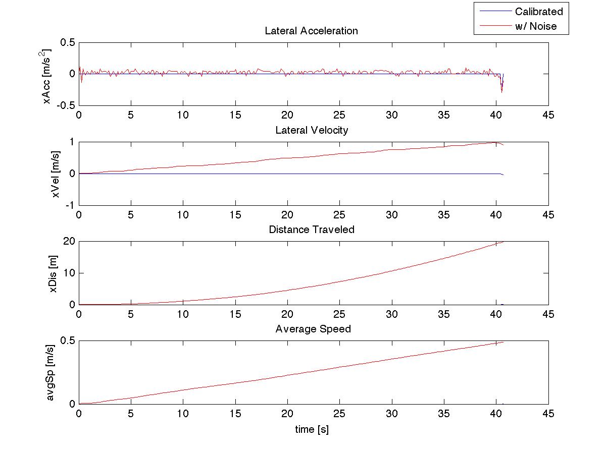
An example that epitomizes the issue with Dead Reckoning
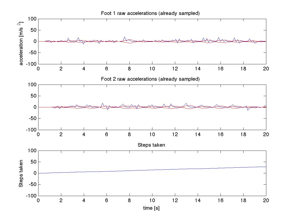
In this data set, we had an accelerometer sit on the table, do nothing and see what kind of data results from it. The blue line is the data we had calibrated to be zeroed out beneath a certain threshold. The red is raw accelerometer data thats been scaled to match units.
As can be seen, over 40s, the distance thats measured is 40m, when reality would define the distance as an appropriate 0. One might say that this is not entirely valid - this demonstrates why we need a noise threshold around 0, but the actual data should be much closer, yes? After all, having noisy data within +/- .2 m/s^2 is more significant when youre staying still than when youre moving. However, we run into sampling issues and timing, which generate plots like this:
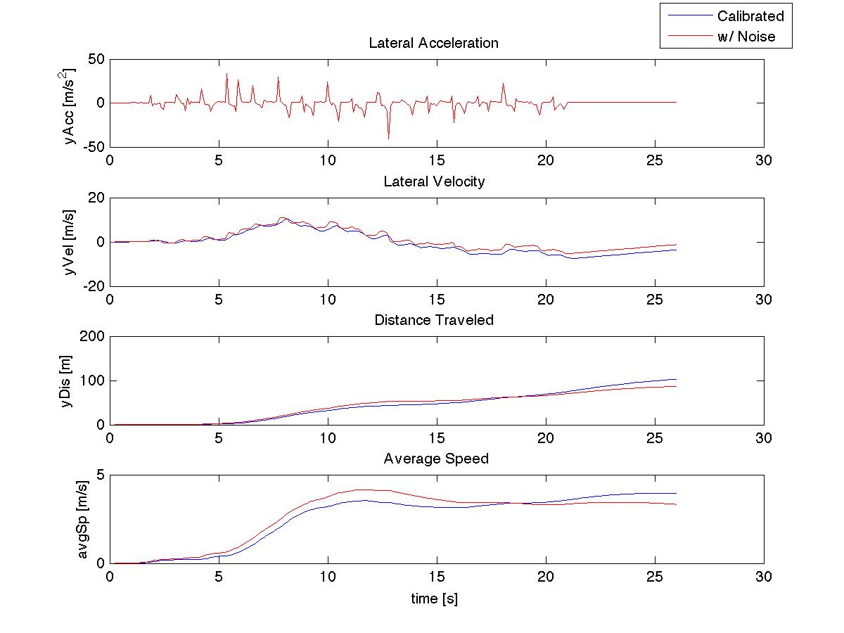
Noisy y-axis data
This is clearly not sitting still, and the noise correction does help, but overwhelmingly, the use of dead reckoning throws the data off considerably.
The step counter was not much better - we had hoped to define a step as when the vertical velocity changes signs from negative to positive, representing that downward stop. In reality, we got graphs like these:
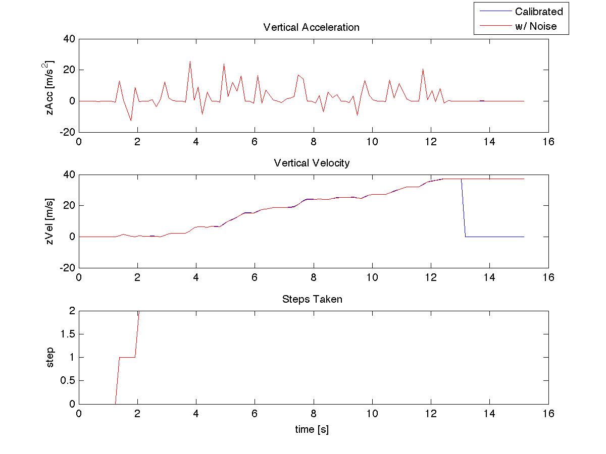
Noisy z-axis data
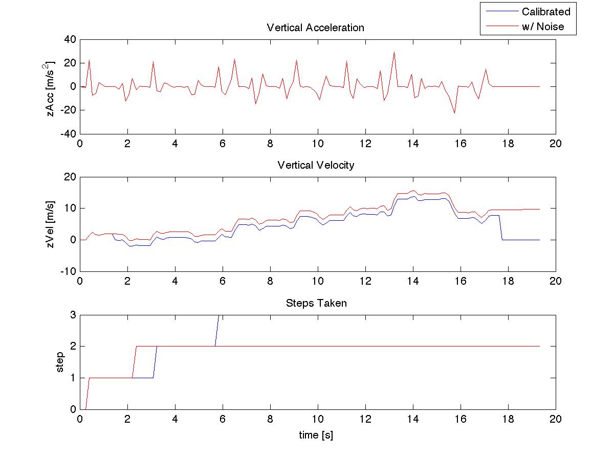
Noisy z-axis data2
Again, we can clearly see the issue with Dead Reckoning.
So we now find ourselves exploring the idea that is ultimately implemented in our final design - using the impulse to sense large accelerations. When we first derived this idea, we used an arbitrary threshold to compare acceleration to. At this point, we only had one accelerometer on one leg, so our minimum delay was different. We quickly discovered the fallacy in this setup: this worked beautifully for Tim, and Tim could walk and get steps to within 4 every 30 (which was a huge improvement over 3 steps recorded total). However, Aarons walk was substantially weaker (likely due to the presence of a brace), and never triggered a step.
After analyzing the raw acceleration data, we decided to implement the running average as the threshold and adapt the other accelerometer for the leg. (NOTE: prior to now, we had implemented a second accelerometer in hopes of trying to find a very noise reduced location for dead reckoning. To no avail, of course.) Below is one of the first tests with this new running average:
Raw z-axis data
This worked well. It recorded steps that had previously been too small to count, and it wasnt overcounting. But this only worked for walks up to a certain speed. We tried a few tests with a faster walk and a run, and realized that although the threshold had easily been passed, the steps were not logging because of the delay we had enforced. For us, this was an indication that there needed to be a different delay for faster paces.
When we were trying to look at the data and derive a method for recognizing faster steps, we were stuck initially. Everything seemed to be based on data that we had already logged, but there was no way for the system to check for this ahead of time. Then we had the idea to re-graph the acceleration data from a series of data samples, but with equal axes this time. Honestly, there was a bit of desperation involved and we were nearing the end of our wit.
Slow Walk data
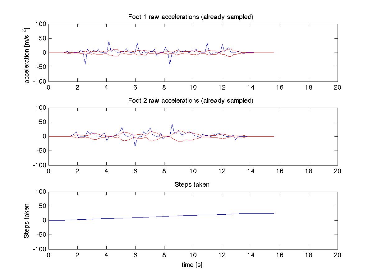
Normal Walk data
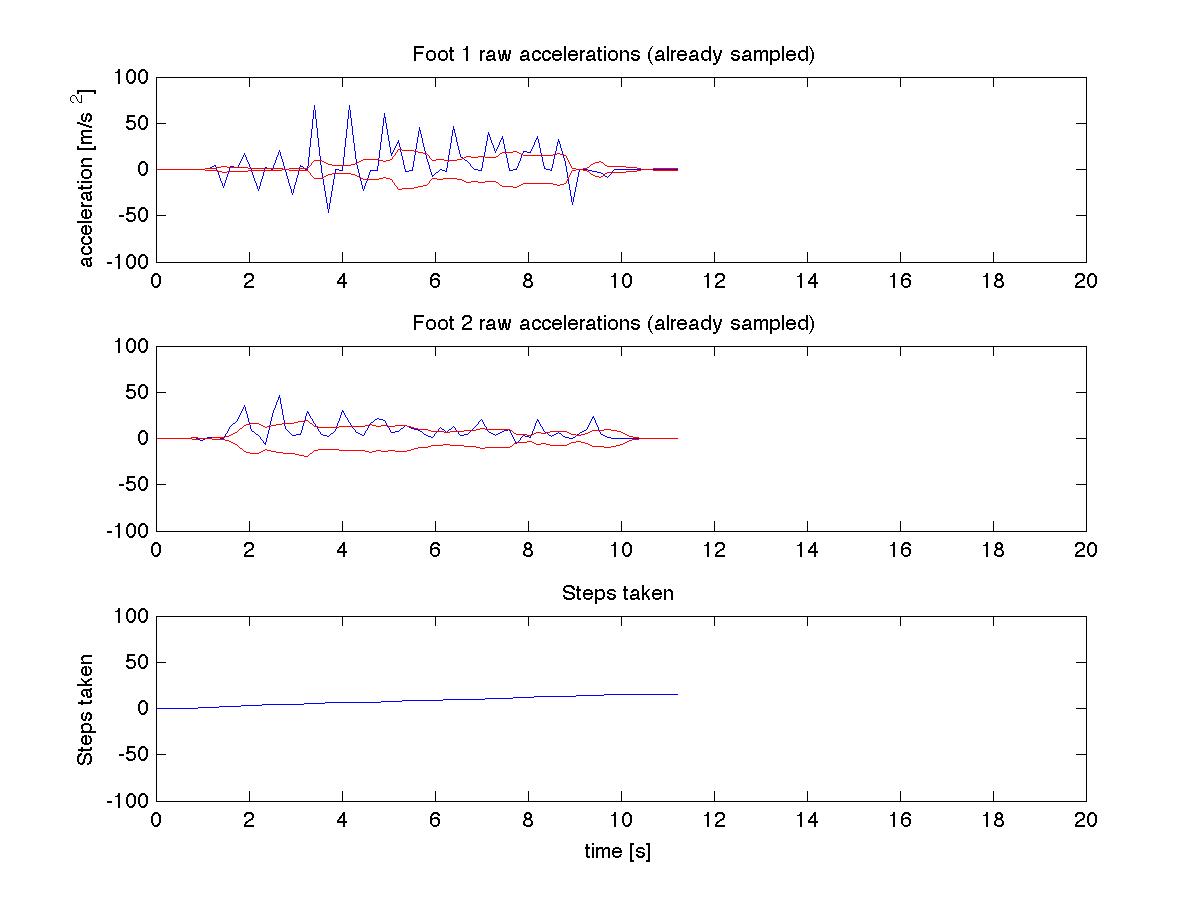
Quick Walk data
Running data
It became clear almost immediately - it was very easy to see how the data compared: faster steps were obviously observable by the narrower peaks, but the spikes were much sharper. This spoke to the idea of using jerk to determine what thresholds to use. Again, the data was really sharp and noisy, so we again used a running average, which proved to be very useful. We could even watch as Tim started off walking and ramped up his speed to a jogging speed, and then back down again.
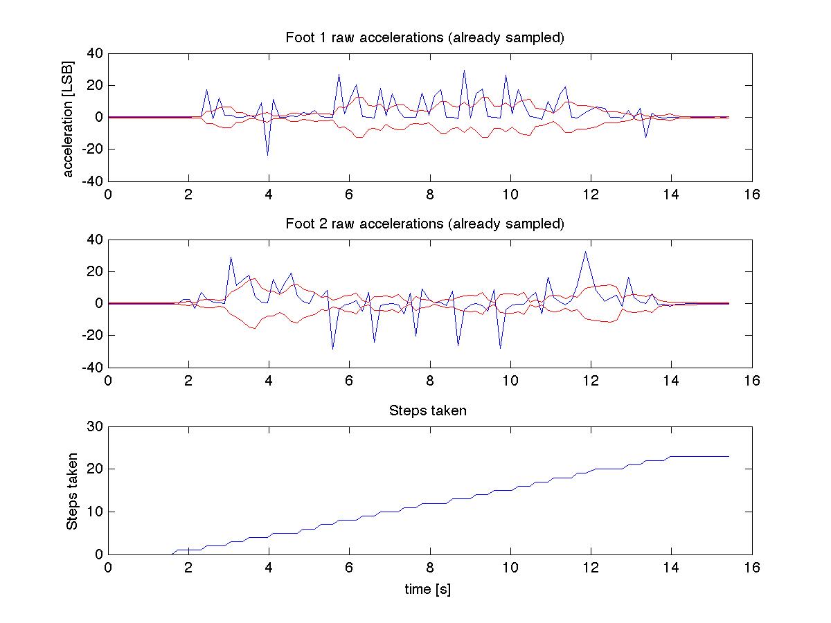
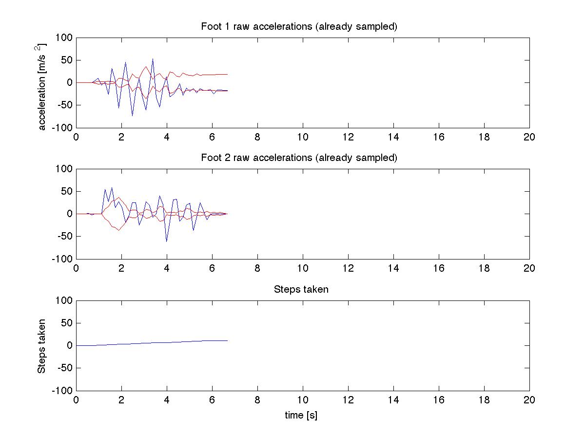
When we incorporated that with his stride length, we could obtain the following data graphs. NOTE: the middle graph represents the pace, and continually updates with each step. The blue step is the current frequency, and the red is the running average of the step frequency. The MATLAB code was not being changed for best viewing and was just plotting out data.
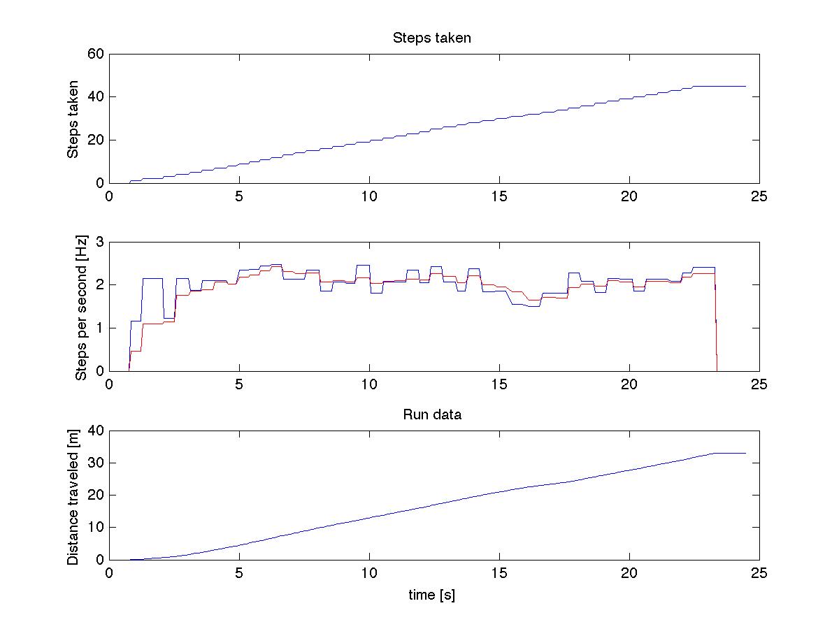
Walk 1
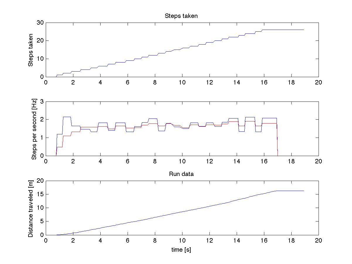
Walk 2
Its obviously not 100%, as the stride lengths and thresholds to differentiate slow walking from normal walking from fast walking from running is completely arbitrary and based on a few data samples. But, in comparison to dead reckoning, weve found something that has a much much higher and more consistent accuracy.
Regarding the accuracy, there are two main sources of error: the beginning and end of step data. The beginning has the running average slowly ramp up to some value, so the first few steps will probably be undercounted in the distance. On the other hand, the timer to wait for another step is rather generous, and can log quite a bit of distance before recognizing no more incoming steps. Over a longer distance, these sources of error may not occur too often, so if theres a better method to relate pace and stride length, the accuracy should improve a lot.
Appendix C: Source Code
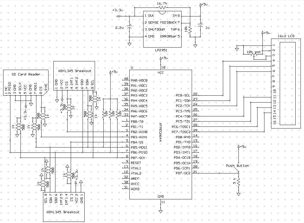
Appendix D: Schematics
Appendix E: Budget Considerations
| Item | Source | Unit Cost | Quantity | Total Price |
|---|---|---|---|---|
| ATmega644 | Purchased in ECE 4760 Lab | $6.00 | 1 | $6.00 |
| 9V battery | Purchased | $2.00 | 1 | $2.00 |
| LCD (16x2) | Purchased in ECE 4760 | $8.00 | 1 | $8.00 |
| Custom PCB w/ Max233CP | ECE 4760 Lab | $7.00 | 1 | $7.00 |
| 2 inch solder board | ECE 4760 Lab | $1.00 | 4 | $4.00 |
| Header Pin | ECE 4760 Lab | $0.05 | 73 | $3.65 |
| Header Socket | ECE 4760 Lab | $0.05 | 63 | $3.15 |
| MicroSD card & Adaptor | Purchased | $10.00 | 1 | $10.00 |
| Molex SD Card Reader | Sampled | free | 2 | $0.00 |
| ADXL345 w/ Breakout Board | Borrowed | $0.00 | 2 | $0.00 |
| LP2951 | ECE 4760 Lab | free | 1 | $0.00 |
| 10k ohm potentiometer | ECE 4760 Lab | free | 1 | $0.00 |
| Push Button | ECE 4760 Lab | free | 1 | $0.00 |
| 10k ohm resistor | ECE 4760 Lab | free | 1 | $0.00 |
| 10k ohm potentiometer | ECE 4760 Lab | free | 1 | $0.00 |
| 5k ohm resistor | ECE 4760 Lab | free | 2 | $0.00 |
| 1k ohm resistor | ECE 4760 Lab | free | 22 | $0.00 |
| 500 ohm resistor | ECE 4760 Lab | free | 3 | $0.00 |
| 2.2uF capacitor | ECE 4760 Lab | free | 1 | $0.00 |
| 1uF capacitor | ECE 4760 Lab | free | 1 | $0.00 |
| Total | $43.80 |
Appendix F: Division of Labor
| Aaron Ho | Combined | Tim Hu |
|---|---|---|
| Step detection algorithm | Systems Level Design | ADXL Hardware & Software |
| SD card implementation | Debugging and Troubleshooting | Device Soldering |
| Voltage regulator | Documentation | Primary Test Subject |
Appendix G: References
Datasheets:
Vendor Sites
Borrowed Code/Designs
- Initial dead reckoning code - adapted from Aaron Berks Dead Reckoning
- TinyRealTime
- ADXL345 - adapted from SparkFuns arduino examples
- SPI - adapted from ECE4760 SPI
- GNU public license lcdlib.c lcdlib.h
- FATFS - elm_chan
- "Beerware License" - trtUart.c , trtUart.h , uart.c , uart.h
Background sites/papers:
- Dead Reckoning - Aaron Berk
- Pedometer - Analog Devices
- Pedometer2 - Analog Devices
- SPI - adapted from ECE4760 SPI
- GNU public license lcdlib.c , lcdlib.h
- FATFS - elm_chan
- FATFS - frank-zhao
- Previous Projects (See Appendix B)
- Tiny Real Time - Cornell University
- SPI - Cornell University
- SPI - elm-chan