Cornell University ECE4760
Interrupts and exceptions
PIC32MX250F128B
Interrupt mechanism
The PIC32 can generate a number of hardware interrupts from peripherial modules, external sources, and software exceptions from the CPU. All IRQs (interrupt requests) are sampled on every rising edge of the SYSCLK and latched in associated Interrupt Flag registers. A latched IRQ flag will only cause change in program flow if the corresponding Interrupt Enable bit in the Interrupt Enable register is set. The Interrupt Controller selects the highest priority IRQ flag among all the pending and enabled IRQs and presents the associated vector number and priority-level to the processor core.
When servicing an interrupt, the processor core pushes the Program Counter into the Exception Program Counter (EPC) register in the CPU and sets the Exception Level (EXL) bit (Status<1>) in the CPU, then it branches to the vector address calculated from the presented vector number. The EXL bit disables further interrupts until the application explicitly reenables them by clearing the EXL bit. In the ISR, the processor returns to mainline code when the Exception Return (ERET) instruction is executed. The ERET instruction clears the EXL bit, and restores the Program Counter. Before actually executing user ISR code, the interrupt handler routine must generate a prologue and an epilogue to configure, save and restore all of the core registers, along with General Purpose Registers. Generally in C, all of the modifiable General Purpose Registers must be saved and restored by the prologue and the epilogue, which is usually performed by the compiler. All interrupt registers are cleared and interrupts disbled at RESET.
Warning: The default interrupt/exception handler function is to RESET the CPU!
That means that if you enable an interrupt for which you did not write an ISR, the system will periodically RESET!
The first symptom you are likely to notice is that the TFT display is flashing white at a few Hz.
•If you perform any arithmetic divide-by-zero, the system will reset.
•If you index an array with a huge (or negative index) which implies an address outside of implemented memory.
•If you exit from a scheduled thread function (by allowing a function return) the system will reset.
(You must explicitly exit from from a spawned thread function)
Specific Interrupt Features
The PIC32 Interrupts Controller module includes the following features:
• Our CPU version supports about 60 peripherial interrupt sources and up to 44 interrupt vectors (in multivector mode).
• There are up to five external interrupts with edge polarity control.
INt0 is on RB7 for our package.
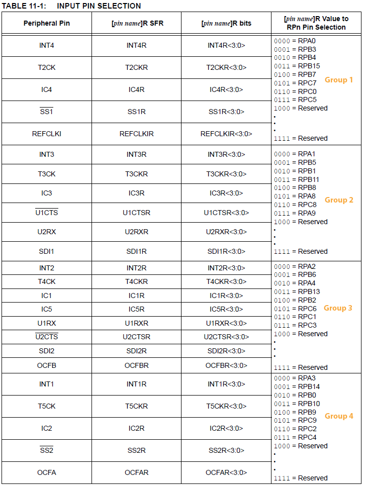
INT1 to 4 are on PPS input control with one external interrupt for each PPS group.
Example INT2: specify PPS group, signal, logical pin name
PPSInput(3, INT2, RPA2); //Assign INT2 to port pin RA2-- Physical pin 09 on 28 PDIP
but INT2 could be assigned to any (or none) of
RPA2, RPB6, RPA4, RPB13, RPB2
• There are seven user-selectable priority levels for each vector (I generally use the default priorities)
• Software can generate any interrupt by setting the associated flag bit using PLIB function:
void INTSetFlag(INT_SOURCE source)
See Interrupt Sources from PLIB reference for the flag source names.
Software Exceptions/traps
There are several program conditions which can cause a software exception (also called a trap).
Interrupt information sources
Performance
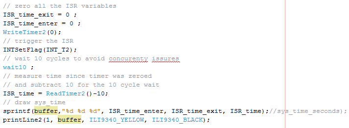
Minimal ISR time: In C, the compiler generates a prologue and an epilogue to the user ISR code. The prologue and epilogue save and restore CPU state. The prologue and epilogue can each be as short as 11 opcodes each if all you do in the ISR is clear the IRQ flag. NOTE that in real programs you NEVER set the IRQ flag, but for this example we will force an interrupt! The way to show the minimum for the timer2 interrupt is to write a thread which includes:
WriteTimer2(0);
INTSetFlag(INT_T2);
wait1 ; // wait for 1 cycle to make sure the ISR happens
ISR_time = ReadTimer2()-1;
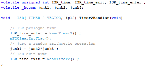
With a minimal ISR:
void __ISR(_TIMER_2_VECTOR, ipl2) Timer2Handler(void)
{ mT2ClearIntFlag(); }
The assembly code for the whole ISR, including prologue and epilogue, is 24 assembly instructions. By actual measurement it takes 49 cycles from the flag-clear operation to the timer-read operation in the code above. Since many of the instructions are 2 cycle read/store instructions, the time is reasonable. This corresponds to a 816 KHz absolute maximum ISR rate. Without the one cycle wait, the code reports a 14 cycle ISR delay. I think it is due to the actual ISR occuring AFTER the timer read and BEFORE the assignment.
Effect on time of adding code:
Full ISR time: If you use arithmetic or function call logic in the ISR, then there can be a total of 33 instructions in both the prologue and an epilogue, taking a total of ~100 cycles. The 100 cycles it takes to enter/leave an ISR places an upper limit on ISR rate, for ISRs that do any useful work. At SYSCLK=40 MHz the enter/leave code requires 2.5 microseconds, so the absolute upper limit ISR rate is 400 KHz.
You can see the assembler code generated to do this in the MPLABX IDE by choosing:
Window -> Debugging -> Output -> Disassembly
The prolog code saves stack pointer and registers :
137: void __ISR(_TIMER_2_VECTOR, ipl2) Timer2Handler(void)
138: {
9D001BF4 415DE800 RDPGPR SP, SP // does nothing on our processor, I think(no shadow registers)
9D001BF8 401A7000 MFC0 K0, EPC //move coprocessor 0 register to a general register.
Coprocessor 0 does the exception handling. EPC is the exception program counter
It contains the address of the instruction that was running when the exception occurred.
9D001BFC 401B6000 MFC0 K1, Status //move coprocessor 0 register to a general register.
The status register, cp0 register 12, is used both to configure interrupts,
and get more information about the exception that occurred.
9D001C00 27BDFF88 ADDIU SP, SP, -120 // define a stack frame for ISR
//$k0 and $k1 are just aliases for registers $26 and $27 respectively
9D001C04 AFBA0074 SW K0, 116(SP) // store word SW rt, offset(base)
9D001C08 AFBB0070 SW K1, 112(SP)
9D001C0C 7C1B7844 INS K1, ZERO, 1, 15 // isolate bit 0 of k1
9D001C10 377B0800 ORI K1, K1, 2048
9D001C14 409B6000 MTC0 K1, Status // move modified k1 back to coprocessor
9D001C18 AFBF005C SW RA, 92(SP) // save return address on stack
9D001C1C AFB90058 SW T9, 88(SP) // save temp register on stack
9D001C20 AFB80054 SW T8, 84(SP)
9D001C24 AFB10050 SW S1, 80(SP)
9D001C28 AFB0004C SW S0, 76(SP)
9D001C2C AFAF0048 SW T7, 72(SP)
9D001C30 AFAE0044 SW T6, 68(SP)
9D001C34 AFAD0040 SW T5, 64(SP)
9D001C38 AFAC003C SW T4, 60(SP)
9D001C3C AFAB0038 SW T3, 56(SP)
9D001C40 AFAA0034 SW T2, 52(SP)
9D001C44 AFA90030 SW T1, 48(SP)
9D001C48 AFA8002C SW T0, 44(SP)
9D001C4C AFA70028 SW A3, 40(SP)
9D001C50 AFA60024 SW A2, 36(SP)
9D001C54 AFA50020 SW A1, 32(SP)
9D001C58 AFA4001C SW A0, 28(SP)
9D001C5C AFA30018 SW V1, 24(SP)
9D001C60 AFA20014 SW V0, 20(SP)
9D001C64 AFA10010 SW AT, 16(SP) // save on stack
9D001C68 00001012 MFLO V0, 0 // move LO reg mult result to a register
9D001C6C AFA20064 SW V0, 100(SP) // and save it
9D001C70 00001810 MFHI V1, 0 // move HI reg mult result to a register
9D001C74 AFA30060 SW V1, 96(SP) // and save it
// === start of user ISR code
===
139: int junk;
140: ISR_time = ReadTimer2();
Copyright Cornell University June 24, 2019