ECE 4760: Laboratory 1
Digital Capacitance Meter.
Introduction.
You will produce a digital capacitance meter (DCM) which displays the capacitance on the graphic LCD. The DCM will
measure capacitances from 1 to 100 nF.
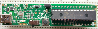
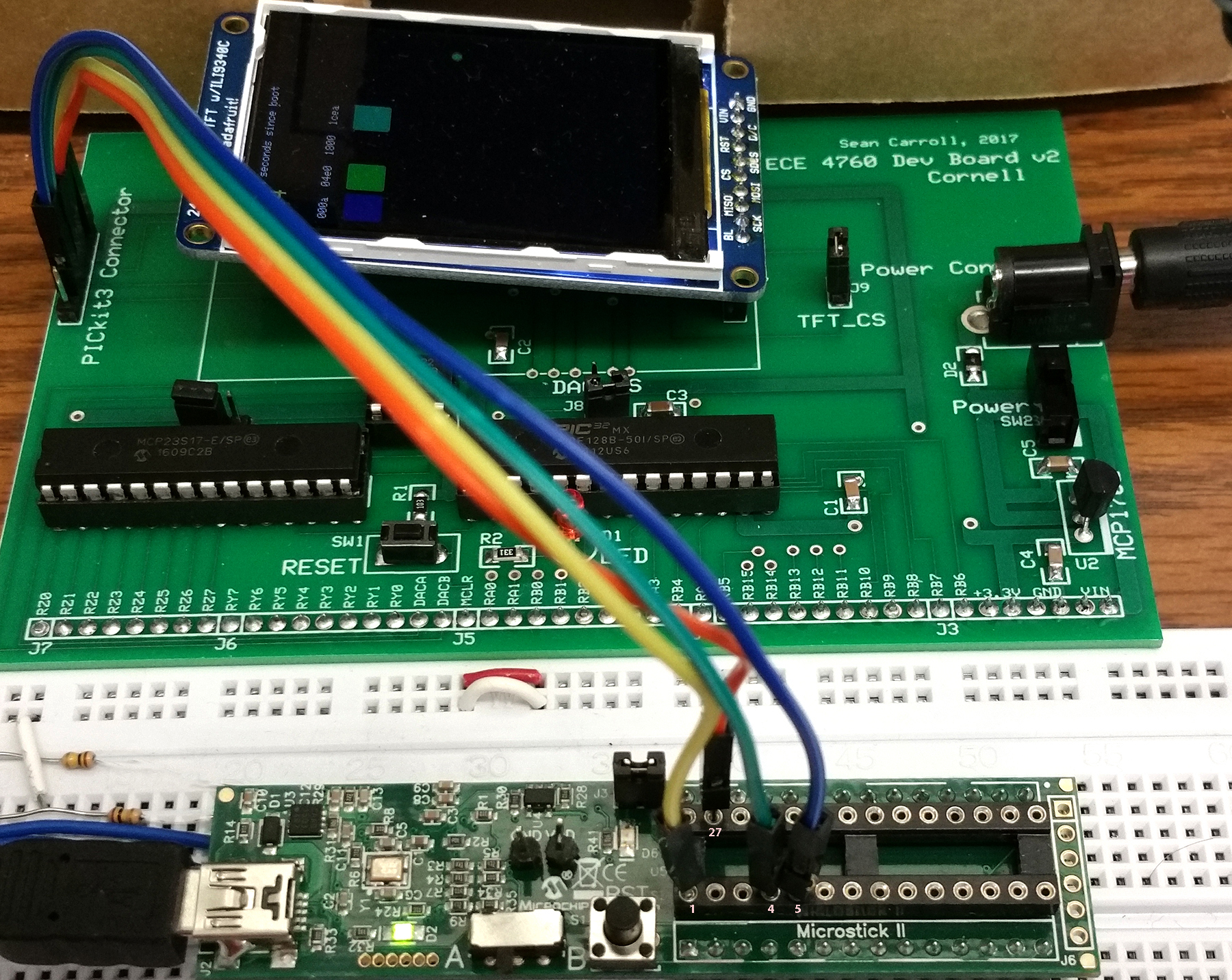
But first you need to set up a board, arrange jumpers, learn how to connect peripheral devices and use the compiler. I strongly suggest that you use some of the time during the first lab exercise to build your own PIC32 board. Once you do that, the Microstick shown below will become the programmer for the new board.
Hardware
The Microstick2 hardware you will be using to
support the PIC32 microcontroller is a small board providing:
- A target microcontroller (mcu) with onboard flash program memory, timers, ADC, and other peripherials.
- A 3.3 volt, 300 mA regulator.
MCP1727
(DFN package marked CAAQ)
- A USB programming/debugging/power connection.
- A reset button and one user LED.
- A programming control switch. It MUST be set to the 'A' position as shown at the bottom-center of the board.
- AFTER you build your own board, you will use the MIcrostick2 as a programmer (see below)
Instructions on building the boards.
The Microstick2:
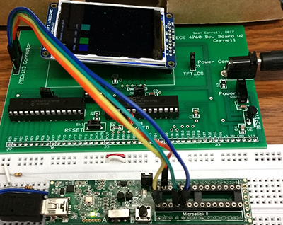
In the initial testing phase of this lab, you are going to connect a TFT LCD screen to use for debugging and results.
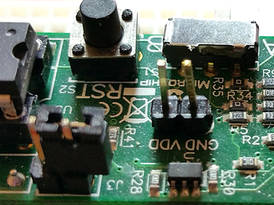
The connections will be much like the photos on the TFT page, but you will get Vdd from the connection in the middle of the Microstick2.
You may want to solder a header pin there. Turns out that the GND and Vdd pins are not quite 0.1 inch apart, so you need to
bend the header slightly to make it fit. Also note that the jumper in the lower left of the image below is unmounted to turn off
the on-board LED.
Connections to MCU
The MCU peripherials can be configured to different pins, so some planning is necessary to fit the pieces together.
For this lab I suggest the following:
- TFT uses
pins 4,5,6, 22 and 25 (RB0, RB1, RB2, MOSI1, SCLK1)
SCK: connected to RB14 on the PIC
MOSI: connected to RB11 on the PIC
CS: connected to RB1 on the PIC
SDCS: left unconnected as I'm not using the microSD card for this
RST: connected to RB2 on the PIC
D/C: connected to RB0 on the PIC
VIN: connected to 3.3V supply
GND: connected to gnd
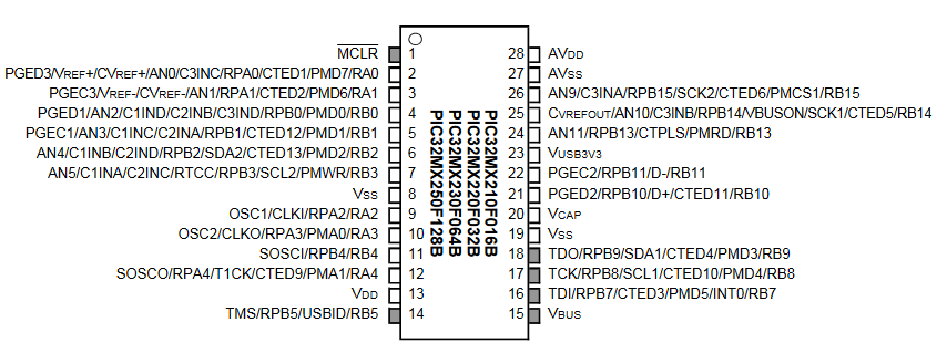
- Comparator 1 uses
C1INA positive input pin 7 (port B bit 3, or RB3)
Negative input internally connected to
IVref=1.2 +/- 0.06 volts
C1OUT
is in PPS output group 4, could use RPB9 which is pin 18
- Input capture 1
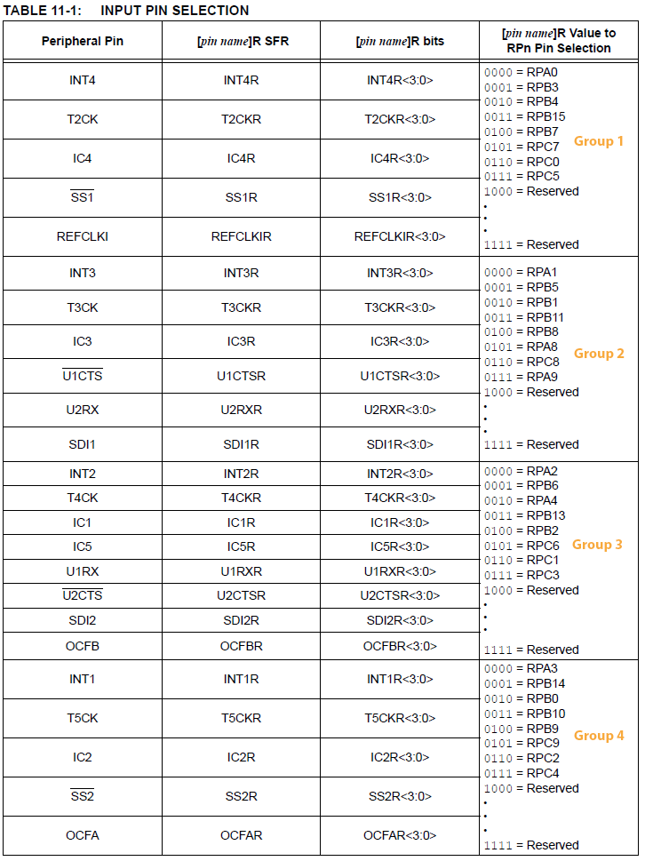
IC1 signal is IC1 is in PPS input group 3, could use RPB13 which is pin 24
Software
Software you will use is freely downloadable and consists of:
- MPLABX version 3.05
(near bottom of page choose Downloads Archive)
- XC32 compiler version 1.40 (near bottom of page choose Downloads Archive)
- plib (near bottom of page choose Downloads -> scroll to bottom) (local copy)
More information
- Getting started with PIC32
- MPLABX IDE users guide
- 32_bit peripherials library -- PLIB examples (ZIPPED) -- (full Legacy PLIB 115 MB)
- 32 bit language tools and libraries including C libraries, DSP, and debugging tools
- XC32 Compiler Users Guide
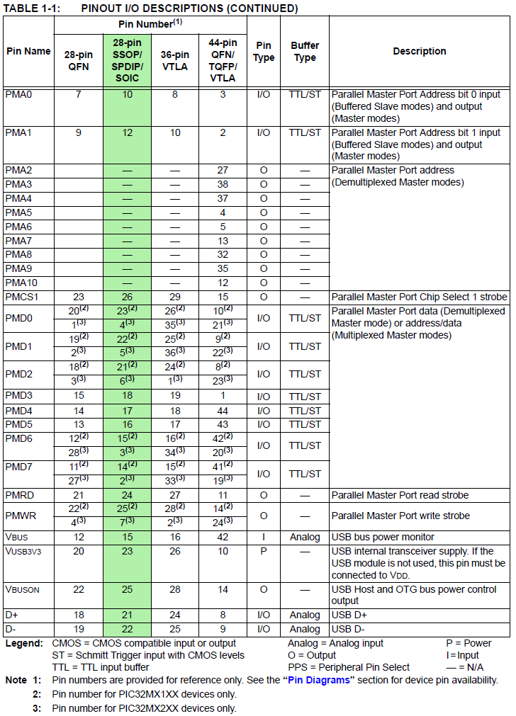
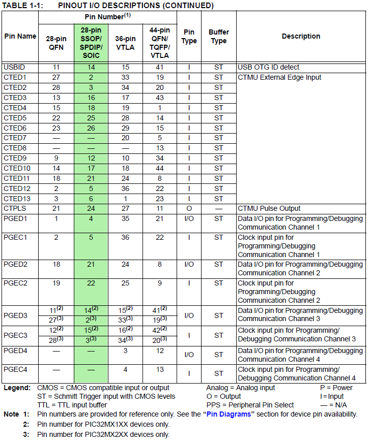
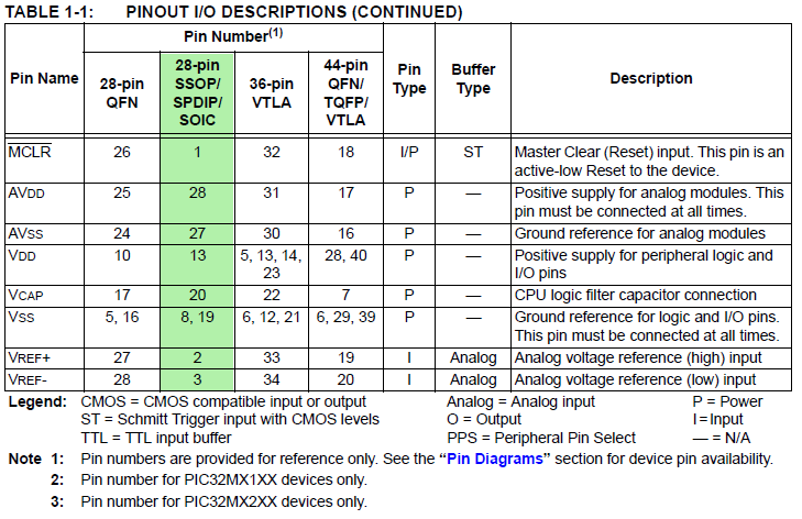
- PIC32MX2xx datasheet -- Errata
- MicrostickII pinout
- PIC32MX250 configuration options
- JTAG enable overrides pins 13, 14, and 15
- Primary oscillator enable overrides pins 9 and 10
- Secondary oscillator enalbe overrudes pins 11 and 12
- PIC32 reference manual (local copy)
(this is HUGE -- better to go to PIC32 page, then Documentation>Reference Manual and choose the section)
- Specific pages from the PIC32 datasheet
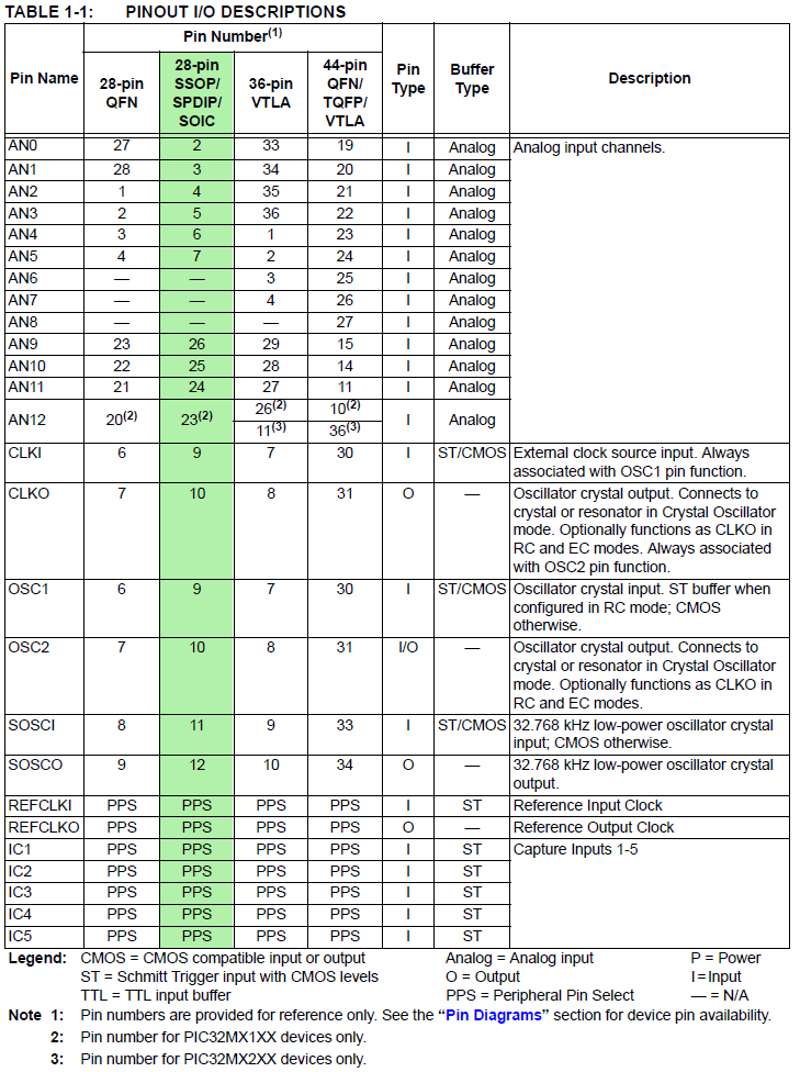
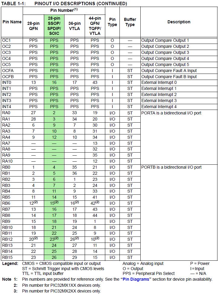
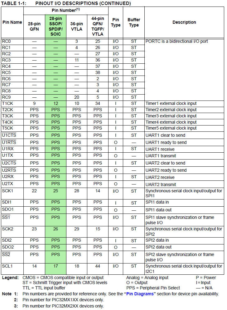
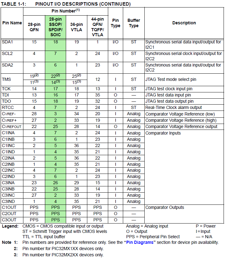
- PIC32MX250F128B PDIP pinout by pin
- PIC32MX250F128B ::: Signal Names=>Pins ::: 1, 2, 3, 4, 5, 6, 7 PDIP highlighted in green (for PPS see next tables)
- PIC32MX250F128B Peripheral Pin Select (PPS) input table
example: UART receive pin ::: specify PPS group, signal, logical pin name
PPSInput(2, U2RX, RPB11); //Assign U2RX to pin RPB11 -- Physical pin 22 on 28 PDIP
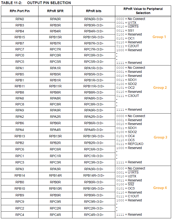
- PIC32MX250F128B Peripheral Pin Select (PPS) output table
example: UART transmit pin ::: specify PPS group, logical pin name, signal
PPSOutput(4, RPB10, U2TX); //Assign U2TX to pin RPB10 -- Physical pin 21 on 28 PDIP
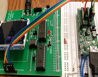
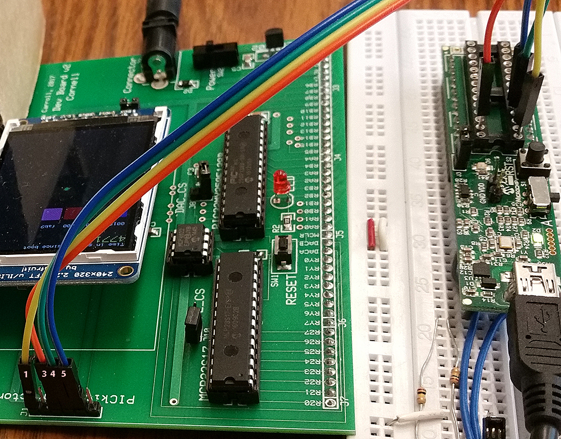
Microstick2 as a programmer
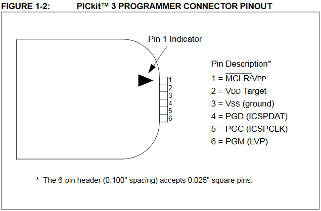
The connections to the microcontroller socket on the Microstick2 act like the standard programming signals from the PICKIT3, the programmer which was used to develop the boards you will build. On both the big and small board, J1 marks pin1 of the 6-pin ICSP header.
| Signal |
PICkit3 (ICSP)
connector on board |
Microstick2
DIP Pins |
| MCLR |
1 |
1 |
| ground |
3 |
27 |
| prog data (PGD) |
4 |
4 |
| prog clock (PGC) |
5 |
5 |
A wiring example is shown below. Note that pin 1, MCLR, is only available on the Microstick2 DIP socket as shown.
When you click on the images below, you will get enlargments with the pin numbers indicated.
Procedure
- For most of the semester you will be useing the TFT LCD for output and debugging.
Read the TFT page, then wire it up as summarized above, and run the run the test code below.
If you built the big board, the the wiring is done for you, if you attach the TFT_CS jumper.
You will need to use some of the graphics library calls described there in this lab.
The (ZIP for TFT) includes the project, source and libraries for TFT and for Protothreads, and has serial and dubugging turned off.
The Protothreads library has appropriate defines disabled (see above).
Test code: TFT_test_BRL4.c. -- displays color patches, system time, and moves a ball.
- You may want to refer the the ProtoThreads page for the general threading setup.
But note that the UART functions mentioned on that page were deleted for TFT compatability.
The following test code shows how to set up a timer input event capture, which you will need to do for this lab.
Test code: Timer_catpure_signal_gen_1_1.c, ZIP includes TFT
- Timing of all functions in this lab, and every exercise in this course will be handled by interrupt-driven counters, (including the builtin functions in ProtoThreads) and not by software wait-loops. This will be enforced because wait-loops are hard to debug and tend to limit multitasking. You may not use any form of a delay(mSec) function.
- You can connect the oscilloscope to the computer with a USB cable (type-B connector) attached to the back of the oscilloscope (not the type-A connector on the front).
To use the Tektronix software on the PC:
- Search for
OpenChoice Desktop in the start menu, and start the program.
- When the main panel appears, choose
Select Instrument.
- In the select dialog box, choose the
USB device, and click OK.
- Back in the main panel, click
Get Screen.
- Copy or save the image or data to your lab report.
Capacitance measurement
The approach we will use is to measure the time it takes for a RC circuit to
charge a capacitor to a given level. Using the IVref internal voltage reference, then the level will be v(t1.2)=1.2±0.06 . Since the internal reference has 5% possible error, you will need to measure the voltage for your chip. Specifically,
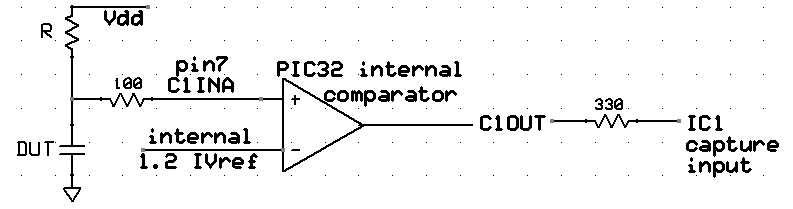
we will use the internal analog comparator as shown in the following
diagram to trigger a timer capture event. The C1OUT pin needs to be connected to one of the event capture channels, with IC1 shown. Since R will be known, we can get C because the voltage on the capacitor v(t)=Vdd(1-exp(-t/τ)) with τ=R*C.
The capacitor shown is the device you are trying to measure.You must choose R
so that the capacitor charging time is not too short or too long. If it is too short you will lose measurement accuracy. It if is too long, the timer will overflow. The 100 ohm resistor limits discharging current when using pin 7 (B3) as an output.
The following code snippet is sufficient to set up internal compare1 and read C1OUT with the oscilloscope.
//set up compare 1

CMP1Open(CMP_ENABLE | CMP_OUTPUT_ENABLE | CMP1_NEG_INPUT_IVREF);

PPSOutput(4, RPB9, C1OUT); //pin18

mPORTBSetPinsDigitalIn(BIT_3); //Set port as input (pin 7 is RB3
)
One thread of your program will have to (in time order):
- Drive C1INA (PortB3) to zero by making it an output and clearing the bit, then wait long enough
to discharge the capacitor through 100 ohms. Since R and the 100 ohm resistor form a voltage divider, to dischage to zero volts with 1% accuracy,
R>100*(100ohms).
- Convert C1INA (PortB3) to an input and start a timer connected to the chosen capture unit.. The capacitor will start
to charge toward Vcc.
- Detect when the voltage at C1INA (PortB3) is greater than than the IVref. That is, you will have to record when the comparator
changes state. Do this by connecting the comapator output to the input capture IC1. Using input capture gives better timing accuracy and more dynamic range than polling or an interrupt.
- Print capicitance to the TFT.
- Repeat
I suggest that you organize the program as follows:
- Protothreads maintains the ISR-driven, millisceond-scale timing.
- Capture ISR copies IC1 into a variable.
capture1 = mIC1ReadCapture(); The actual IC1 capture is done in hardware.
- Main sets up peripherials and protothreads then just schedules tasks, round-robin.
- Measure Thread
- Does step 1 above
- Waits for the discharge using
PT_YIELD_TIME_msec(wait_time)
- Does step 2 above
- Waits for capture event (step 3)
- Computes the capacitance and updates the LCD.
- waits for 200 mSec using
PT_YIELD_TIME_msec(200)
- Blink Thread Blinks a circle on the LCD as a hearbeat, at 1/second.
Assignment
Timing of all functions in this lab, and every exercise in this course will be handled by interrupt-driven counters, not by software wait-loops.
ProtoThreads maintains a ISR driven timer for you! This will be enforced because wait-loops are hard to debug and tend to limit multitasking.
Write a Protohreads C program which will:
- The LCD should be updated every 200 mSec or so.
- An circle on the LCD should blink about 1/second.
- The capacitance should be measured as quickly as possible as described above.
- The range of capacitances to be measured is 1 nf to 100 nf.
- The program should detect whether a capacitance is present or not and display an appropriate message if no capacitor is present.
- If present, format the capacitance as an ASCII number
and prints the message
C = xx.x nf to the LCD. There should be exactly one digit shown after the decimal point.
When you demonstrate the program to
a staff member, you should demonstrate that the capacitance is correct within
the tolerance of the resistors you use. Your program should not need to be
reset during the demo.
Your written lab report should include the sections mentioned in the policy page, and :
- How you converted time to capacitance
- A heavily commented listing of your code.
- A screen capture of the oscilloscope showing the charge/discharge waveform.
- Explain how you could make the meter autoranging.
Copyright Cornell University
August 30, 2017
