Tricks & Inventions
We would like to list all the tricks we learned during our work for this project. These tricks will prove very helpful for all the students of digital design and specially the users of NIOS II IDE, Quartus II and VGA Controller by Terasic.
-
Hardware/SoftwareInterface:
One of the basic problems students usually encounter when communicating between the software and the hardware. That is to send and receive some data from software to hardware or vice versa.
We developed a very basic two handshaking protocol that can be used to communicate between the software and hardware. This protocol works irrespective to the clock speeds of NIOS II and hardware modules.
2 WAY HANDSHAKING PROTOCOL
The handshaking works like this:
The hardware state machine asserts a ready flag which means that it is ready to accept the data. The CPU provides the data, address and a valid signal. The valid signal is the indication to write. As soon as the hardware gets the valid signal it writes the data at the address provided by the CPU and after writing it asserts a flag which tells the CPU that data has been written. The state machine than goes back to its initial state and asserts its ready for accepting another data. The CPU after getting the writing done signal clears the Valid so that same data is not written again.
The code for hardware stat machine and software function is available in the appendix.
-
How to Display any Colored Image in VGA Controller:
We developed a project that can be used to display any image on the VGA Monitor. It is to be noted that the each pixel will only represent two fifty five colors because of the limited size of the SRAM. Image needs to be converted into a text file using the MATLAB program provided in the appendix. After converting it into the text file please copy paste it into an array of our software program write_sram.c . Remember to remove the multiple commas generated by the MATLAB by using any editor. Just run the program it will write an image into the SRAM. The whole project is provided into the APPENDIX.
-
Changing the Resolution of the VGA Monitor:
It is always better to have a good resolution. Initially the VGA Controller provided by the Terasic is of very low resolution of 320 x 240. One can change the resolution to 640 x 480 in a flick of an eye. There is file called VGA_Param.h in the same directory where all the VGA controller files are stored. Remove the contents of that file and copy paste the contents below.
// Horizontal Parameter ( Pixel )
parameter H_SYNC_CYC = 96;
parameter H_SYNC_BACK = 45+3;
parameter H_SYNC_ACT = 640; // 646
parameter H_SYNC_FRONT= 13+3;
parameter H_SYNC_TOTAL= 800;
// Virtical Parameter ( Line )
parameter V_SYNC_CYC = 2;
parameter V_SYNC_BACK = 30+2;
parameter V_SYNC_ACT = 480; // 484
parameter V_SYNC_FRONT= 9+2;
parameter V_SYNC_TOTAL= 525;
// Start Offset
parameter X_START = H_SYNC_CYC+H_SYNC_BACK+4;
parameter Y_START = V_SYNC_CYC+V_SYNC_BACK;
You have 640 x 480 resolution J. You can further change the resolution but for that you need to calculate the timings with respect to your clock. Please note that above figures with the VGA controller provided by Terasic only.
-
How to Generate an MIF File:
Do you know that you can initialize your RAM or ROM with any kind of numeric data you have in a text file. The MIF or Memory initialization file is used to initialize the memory with any kind of numeric text data. For that you need to generate a MIF file. One thing you can do is to understand the MIF format and write a C code to translate the text file into MIF file. The shorter way to do is to get the text data into a .txt file. Open Quartus II. Go to File menu and select new. A window will appear .Click on the Other Files tab. Select Memory initialization file. Specify the word size of your memory and number of words in it. You will get a window like this:
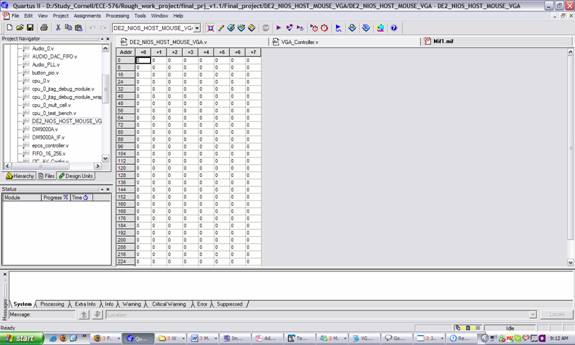
Copy paste the whole text file in that window. If you know the format of the MIF file it would become really easy to understand this concept.
- How to display the same image in different location:
Take advantage of the facts that the VGA controller reads each pixel according to the H_Cont and V_Cont. That is, it reads from left to right and top to bottom. By keeping a separate address counters x & y for the image updated the same way as H_Cont and V_Cont, one can read the image at any position on VGA screen.
To display multiple images of same kind, set x & y address reset signal wisely. For example to display two
in a row in the display area, the x address should be reset after each horizontal line of one image. The y address however should not reset till the row of the images are done, instead it should be increment every time the V_Cont increases.
x----> Reset x----> Reset
-
How to make images overlap each other:
By using a priority encoder mux, we decide which image’s pixel should be displayed. To make sure different images can overlap each other, we treated the color white, 255, as the transparent color. The transparent color would disable the image’s pixel display and let the next image’s pixel in the priority order to be displayed.
Each different image should have its own address counter, and should always be updating regardless the enabling or disabling of the image display. The address counters should consist of x and y parts of the image and updates when H_Cont and V_Cont of the vga controller updates. This way, the image’s data of that specific pixel is always passed to the priority encoder mux to be chosen for display.
-
How to detect continues holding of a mouse button and perform the action desired:
Look at the mouse.c of the DE2 Example, there is a do-while loopis the play_mouse function, which would lead one to think that to place the action desired in that loop, the action will be performed repeatedly. However, this is not true. Inside the do-while loop there is a function called send_int(). This function is inside ptd.c.
The send_int() function has another do-while loop. The program only gets out of the loop if there is an active_bit change or timer runs out. Sadly, holding of a mouse button does not qualify for active_bit change. It might be temping to reduce the timer to get out the loop faster. Unfortunately, such attempt would result a weird mouse movement behavior.
The correct way to solve this problem is to declare one’s desired function in an external function in mouse.c. And, call the function in the do-while loop in the send_int() function in ptd.c. One may need to declare some global variables in mouse.c.
Remember, although holding mouse does not count as active_bit, movement of the mouse does. Thus, if one wants the desired action to be repeated regardless mouse moves or not. One should declare the function in the do-while loop in mouse.c too.
Tips
- It is very usual to get an error indicating Processor Pause while running the NIOS II IDE. The processor is paused because of two reasons. One is that it is being reset at the time of programming and second there is some problem with the PLL file. Try to check the reset of the processor and the remove the unnecessary PLL files generated by the Altera
- The SRAM stores data until the power is removed. Programming FPGA with different .sof files does not make any change to the data of SRAM unless that particular .sof file writes into the SRAM.