Hardware for the Virtual Paint can be broadly categorized into 4 modules
1. Frame grabber or camera
2. Image processing and control unit
3. Memory unit
4. Display unit
Camera module
We used TRDB_DC2 camera development kit from terasic to serve as the frame grabber. This kit consists of a 1.3 megapixel CMOS image sensor and an IDE cable to connect to GPIO port of the DE2 board. The prime reason for choosing this development kit was the ease of interfacing with the DE2 and also for the reason that since this kit is built around the development boards from Altera it comes with a VGA display reference design that be used to directly display the images captured by the camera on to the VGA module saving a lot of extra effort in making the image sensor – FPGA interface work.
TRDB_DC2 kit has a 40 pin connect that connects with the GPIO on board. Out of the 40 pins 20 are reserved for the second sensor. In our project we used only a single sensor to capture the image so only 20 pins were actually used to connect with FPGA board. PIN 1-10 are for DATA1 that contains the actual pixel data as provided by the CMOS sensor. PIXCLK is the pixel clock, that is provided by the CMOS sensor inorder to sync the incoming pixel data and is normally the inverted master clock. PIN 14 is the master clock that has the maximum frequency of 25 MHz that was provided by DE2 on board oscillator. Pixel data is valid during the rising edge of the pixel clock. The Table below gives the complete PIN description for the camera-FPGA interface:
Image Processing and Control Unit
This is the central unit of the whole system. All of the image processing and control is done on Altera DE2 on board FPGA fabric. The ports of the DE2 board that were used for the project were the USB Blaster Port for FPGA programming, VGA Port for connecting to VGA, GPIO1 was used by connecting a IDE cable between the camera module and the Expansion header 1. Toggle Switches on board were used to control the exposure settings of the image sensor but for new exposure settings to take place we need to reset the board first.
Altera DE2 board description
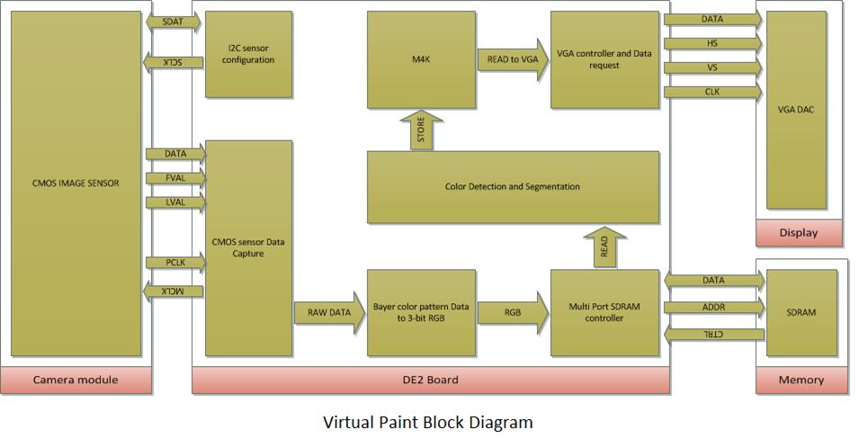
Data coming from the image sensor is captured in the sensor capture module or CCD capture which is then fed to Bayer color pattern data to RGB conversion module. Sensor data is stored in the SDRAM via the SDRAM controller. The main module is the color detection and segmentation module which reads out the pixel value from the image buffer that is the SDRAM for processing. It then stores the corresponding color value for the pixel in the M4K block. The VGA controller reads the M4K memory location and sends the stored color information at the corresponding address to the VGA DAC of the display unit. RAW2RGB module is used to convert image data from Bayer format to RGB format. The details for the Bayer to RGB conversion was included in the CCD module that came with the terasic kit. For understanding the Bayer to RGB conversion we find this link useful.
Below is the block diagram of the camera image sensor interface with the board and the VGA unit:
Color detection and segmentation unit which is the main control unit can be further divided into 3 parts, the color detection & segmentation unit, averaging & center calculation unit and the color selection & paint unit.
For color detection and segmentation we used threshold comparison and relative intensity comparison of the RGB component of every pixel. This part took us a significant time as we tried out different color mappings to have a robust color detection scheme because right color detection is the core of the whole project. To keep it simple and robust we tried to fiddle with the RGB color space to detect the colored tapes correctly that we were using to wrap around our fingers while drawing. Finally we were able to have correct color detection with minimal noise. the RGB scheme that worked for us is as below:
if (R>128 and R> 2(G) and R > 2(B) and G < 128 and B < 128) then RED color
if (R>256and G < 256 and B < 128) then YELLOW color
if (R<128 and G > 320 and B < 128) then GREEN color
The reason why we choose RED and YELLOW colors specifically were because of the high intensity of these colors while they are significantly different from the white color making us filter out the background noise.
In averaging & center calculation unit we have counter value that counts the number of pixels for the detected color and also sums the X coordinates and Y coordinates and then takes an average of these coordinates to compute X center and Y center for the pixel.
Color selection & paint was done using the onscreen color palette that was displayed on the screen and for displaying the color palette we modified the VGA controller so as to reserve a particular section of the screen and display specific colors there. This was done by attaching a mux at the input color stream of the VGA where whenever the address of the VGA pixel falls in a particular range we display a particular value.
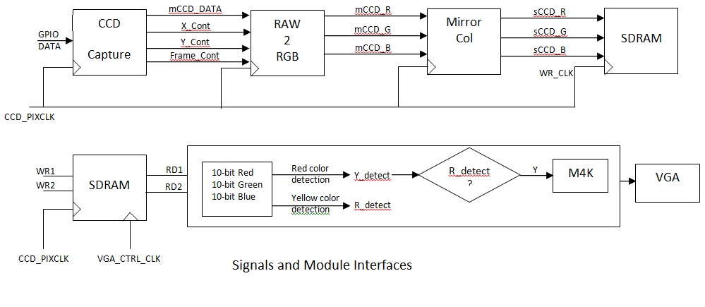
Below is the block diagram showing various module interfaces:
Memory Unit
Image data sent by the CMOS sensor is stored in the 8MB of SDRAM which act as the frame buffer. We also used on chip M4K to store the color information corresponding required pixel addresses generated after the color segmentation of the frame. DE2 has 105 M4K RAM Blocks and 483,840 RAM bits. For the purpose of detecting and storing color information for 2 different colors we used upto 43% of the available M4K.
Display Unit
For the purpose of display we used the standard VGA port available on DE2 board and it was used to connect with both LCD display unit as well as the projector. Due to unavailability of the portable projector in due time we demonstrated the concept of Virtual Paint to draw colored images over any plain surface using a wall and over-head projector in one of the classrooms.