


Hardware Design
VGA Controller
The VGA controller used in the lab was based on the Cartoonifier project. The first vertical sync pulse is delayed by 3 lines due to line buffering.
Bresenham Line Drawing Algorithm
The Bresnham Line module used in this project was based on the Face Tracking + Perspective Projection project. 2 handshake protocols are maintained between the line drawing state machine and the main state machine to signal the beginning and ending of pixel and line drawing. Vertical and horizontal sync pulses are also connected to the module to ensure SRAM access does not interfere with VGA access.
3D Human Mapping
In order to track the head, left and right arm separately, the incoming camera feed is divided into 3 regions that each body part will be in. Figure 2 below shows how the 640x480 video frame is divided. For each frame, each region in the video feed computes a new centroid by taking the average of all down sampled skin pixels' coordinates that fall within the region. The down sampled data set is used to avoid noisy measurements.
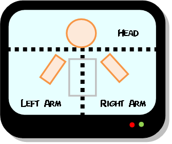
Rectangle and squares are drawn based on the location of the 3 centroids to represent head, left and right arms. Projection is computed by variation the location of the projected square or rectangles by using the upper 6-7 bits of x and y coordinates of centroid as offsets. The tilts of the arms are generated based on the direction vector between the arm centroid and the head centroid. Lastly, the body of the model is draw based on the head centroid location.
Skin Filter Temporal and Spatial Averaging
To reduce noise in the skin pixel measurements, both temporal and spatial averaging is performed. The incoming pixels are first checked to ensure the U and V values are valid. Then the result is added to a 16x16 down sampled set. For a 640x480 screen, there is a total of 40x30 down sampled cells. Thus, after a frame is completed, each cell in the down sampled view contains average skin color for 16x16 pixels. The formula used for spatial averaging is:
To perform temporal averaging, simply do not reset the down sampled cell values when a new frame is available. This way, old values from previous frames can also be included in the average.
Centroid Averaging
Centroids are computed based on the down sampled frame. This means whenever the centroid moves by 1 cell, it has moved by 16 pixels in the 640x480 frame. Since the 3D projections are drawn on a 640x480 screen, averaging is needed in order to make the animation of the projections look smoother. In this case, I modified Bruce's average module. Using the 25MHz VGA clock, the down sampled centroid coordinates (5-6bits) needed 25 padding bits and a shift constant of 21 to generate smooth animation between down sampled cells.
Hardware UI
User can choose between 3 different views via SW[16] and SW[17] on the DE2 board. If SW[16] is not activated and SW[17] is activated, then the direct video feed from the camera will be displayed on the VGA screen. If SW[16] is not activated and SW[17] is not activated, the down sampled skin map will be displayed along with the 3 centroids. If SW[16] is activated, then the VGA screen will plot results stored in SRAM, which contains the 3D projection of a human model.
Relative Standards/Trademaks/Patents
The video feed obtained from the camera as well as the VGA signals are all standard NTSC signals. The skin detection algorithm used in this project is based on a paper written by Ooi. The centroid averaging module was based on Bruce Land's averaging module on ECE 5760 website. The Bresenham Line drawing module was written by members in the Face Tracking+Perspective Projection project. Please see the download page for links to code.