Previous Next
Henri Clarke (hxc2), Michael Rivera (mr858), Priya Kattappurath (psk92)
ECE 4760 Final Project
Fall 2019 (12/13/19)

Happy Little Mixer

Introduction

The Happy Little Mixer is an automatic ink mixer which accepts a hex user input and creates that color by measuring out cyan, magenta, yellow, and black (CMYK) ink. It includes open-loop feedback using a color sensor to correct the generated color, making it as accurate as possible.
full system
The final product!

High Level Design

We wanted to create something that would spark joy in a user and could be fun and interactive. Ideally, an ink mixer could be used to help teach young artists how to mix colors, as well as the principles of hue and saturation. It could also make the process of creating specific colors easier, particularly for colorblind artists. We called it a “happy little mixer” because we were inspired by the well known phrase, “happy little trees,” used by Bob Ross on his show “Joy of Painting.”

Logical Structure

System diagram
Above is a general flow diagram of the system we provided for our demo. The system will initially waits for a serial hex input from the user and then convert it to CMYK values. With these values, we determine how long each servo should dispense its corresponding color.

The system then waits for the user to indicate over serial whether to make a color adjustment or return to the beginning. If the user wants to make an adjustment, we prompt the to hold a sample up to the color sensor for a more accurate reading and then wait for the user to indicate they are ready.

Once ready, the system requests color data from an arduino attached to the color sensor. The system then performs a similar conversion with the color sensor data and compares the observed CMYK values with the expected values. The user is prompted again if they would like to make a color correction. If yes, then the system will attempt to modify the saturation of the appropriate channels.

Hardware and Software Tradeoffs

Initially, our plan was to create a paint mixer, but the viscosity of the paint introduced mechanical issues that we couldn’t figure out in the given time, with the given budget. Consequently, we opted to use printer ink mixed with water to create dyes. Although this solved our initial budget issues, we encountered issues with secure closing mechanisms and leaks. We were also unable to implement closed loop feedback, because the color of dye in liquid form greatly differs to its color on paper.

On the software end, to reduce the complexity of our code, we decided to run our servos off a singular timer with four different output compare units using it as a source. This required that the corresponding duty cycle for each servo be calibrated not only for that specific servo, but also relative to the other servos due to their unique 20ms hold-off requirement.

Background Information

We used some basic arithmetic in the use for color conversion -- from hex, to RGB, to CMYK -- and scaling those results for output. We also used basic arithmetic for error calculations for the feedback system.

It should be noted that for CMYK colors, only two of the CMY values are ever nonzero at any time unless you are working with a grayscale value. Additionally, we had to modify the provided protothreads header file, pt_1_3_3.h, as it had not defined the auxiliary term buffer, which we needed to receive values from the Arduino.

To our knowledge, there are no patents for a similar product, although there are programs that do virtual color mixing. We did not reference these in our development process.

This project complies with industry standards.

Hardware Design

Our initial mechanical design differed from our final design. This was because we changed our mind in deciding to use servos to clamp the surgical tubing after we were in the process of printing the already designed structure, and we decided to prioritize the technical aspects of our project rather than spending time redoing the external structure. We worked modularly and only assembled the entire project in the final week.

When we began to design the outer casing for our color mixer, we knew we needed a place for the CMYK inks, servos, and places to route the servo wires and the tubing. Keeping these ideas in mind, we created a 3D model of our proposed casing, which included levels to hold the ink and servos, holes to route the tubing, and slits for wires. In order to print the casing in a reasonable amount of time, we split the design into three sections.
Casing
Screenshot of casing, designed with Fusion.


This proved very useful, as we were able to modify our original design by rearranging the 3 pieces to be better suited to hold the servos and tubing. We also added wooden spacers, which gave us more vertical space so the tubing could fully extend. Also, instead of using the premade holes in the casing only for tubing, we used them to hold the servos, and later drilled extra holes for the tubing.

We cut our 3 ft of tubing into four pieces. First, we tested to ensure that the servos were capable of pinching the tubing shut. After we determined the correct calibration, we drilled holes into the 3D print to make space for the tubing and added the servos.

Top
bottom
Servos and tubing newly added, top and bottom.


We added wooden spacers to allow the servos to move without hitting the wall of the structure, then hot glued the next layer on. We threaded the tubing through the top holes and used hot glue to secure them in place and create a waterproof layer.

Spacers
Spacers added to elevate top level away from servos.


Next, we drilled holes into the bottom of the plastic bottles to be slightly wider than the tubing. We then placed hot glue around the tubing and slipping the plastic bottle on, then added additional hot glue to create a water seal. We tested this with water to ensure that there was no leakage, and that the servos were still capable of clamping the tubing properly.

Bottles
Reservoirs of ink sealed off using hot glue.


The servos were too low for a cup to fit under, so we sawed some stilts from a scrap block of wood and glued them in for the appropriate height. We also trimmed the tubing to ensure that they wouldn’t get contaminated in the already mixed dye.

stilts
Stilts added to elevate everything from bottom level. Support in the back not shown.


In retrospect, we could have done it more elegantly, but we did not lay out our mechanical setup rigorously enough at the beginning and were too pressed for time to redo it. In addition, the size of our 3D printed pieces were limited by the upper limits of the 3D printer. Despite these challenges, our final product was functional.

Small Board

To mount the PIC32 for this project, we utilized a Small Board designed by Sean Carroll. The Small Board is a breakout carrier for the PIC32. Our motivation for using this was primarily budget constraints while maintaining the familiarity of a breakout board similar to the one we had used for the previous labs in this class.

small board
Sean Carroll's small board.


More on the small board can be found on the class webpage.

Parallax Standard Servos

Our initial plans for this project were to either use motor controlled syringes or peristaltic pumps to dispense paint. However, due to mechanical complexity and budget constraints respectively, we settle on a gravity based system with surgical tubing and servos to clamp them shut. We used standard servos ecause they were readily available at the time courtesy of Joe Skovira.

servo wiring
Servo wiring, from datasheet.
servo timing
Servo timing, from datasheet.


Above are the wiring and timing schemes for the servos from their datasheet. The servos have a power requirement of 4 to 6V and an I/O input range of 3.3 to 5V. The required PWM timing is that pulse widths should be between 0.75ms and 2.25ms, and pulses should be separated by 20ms.

Color Sensor + Arduino

We used the color sensor TCS34725, which we connected according to the datasheet:

color senso to arduino connections
Color sensor to Arduino wiring.


Other than the normal wiring of the Color Sensor (which is in the circuit diagram for the project), we also needed to add additional circuitry between the Arduino transmit pin (pin 1) and the receive pin on the PIC32 (PIN RB13). This is because the Arduino runs on 5V power, and the PIC32 runs on 3.3V. Therefore, we needed to add a low pass filter between these two pins, in order to make sure the PIC32 wasn’t overloaded.

Software Design

CMYK Conversion

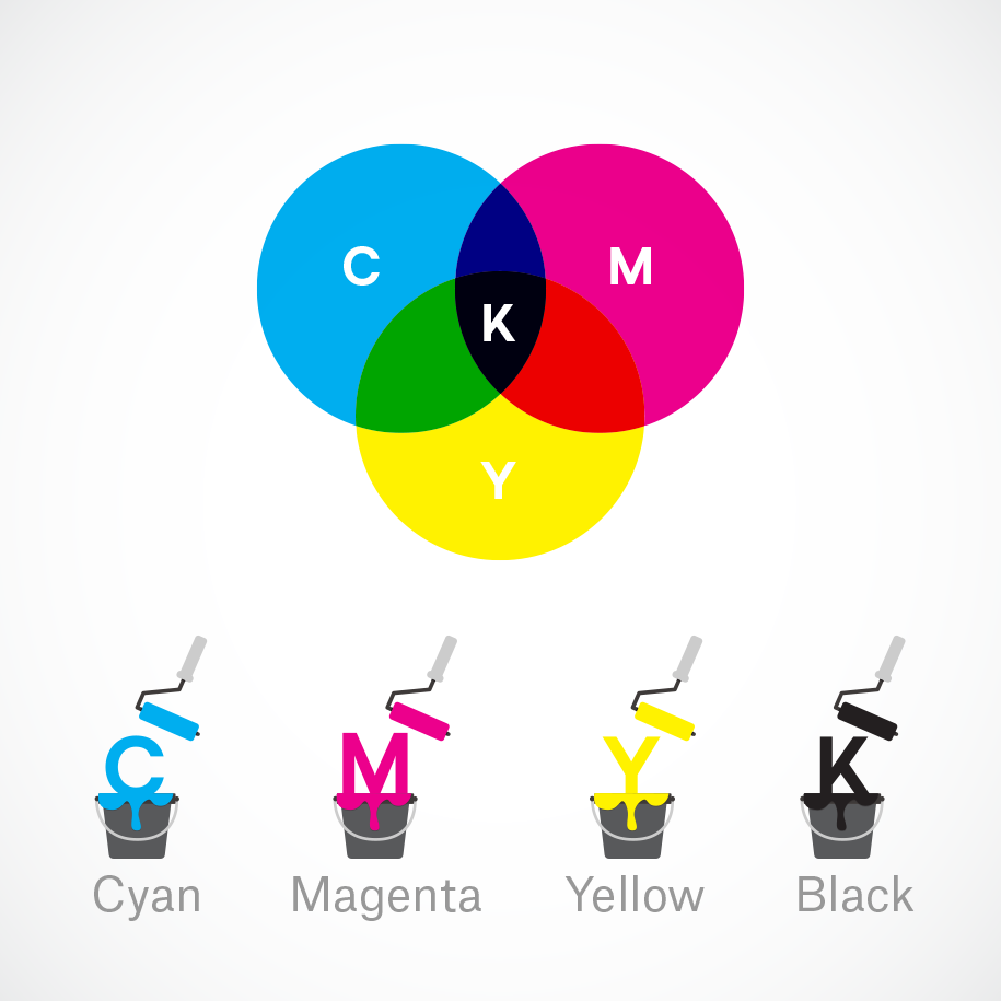
RGB values are colors defined by the amounts of red, green, and blue light they contain. CMYK values are colors defined by the amounts of 
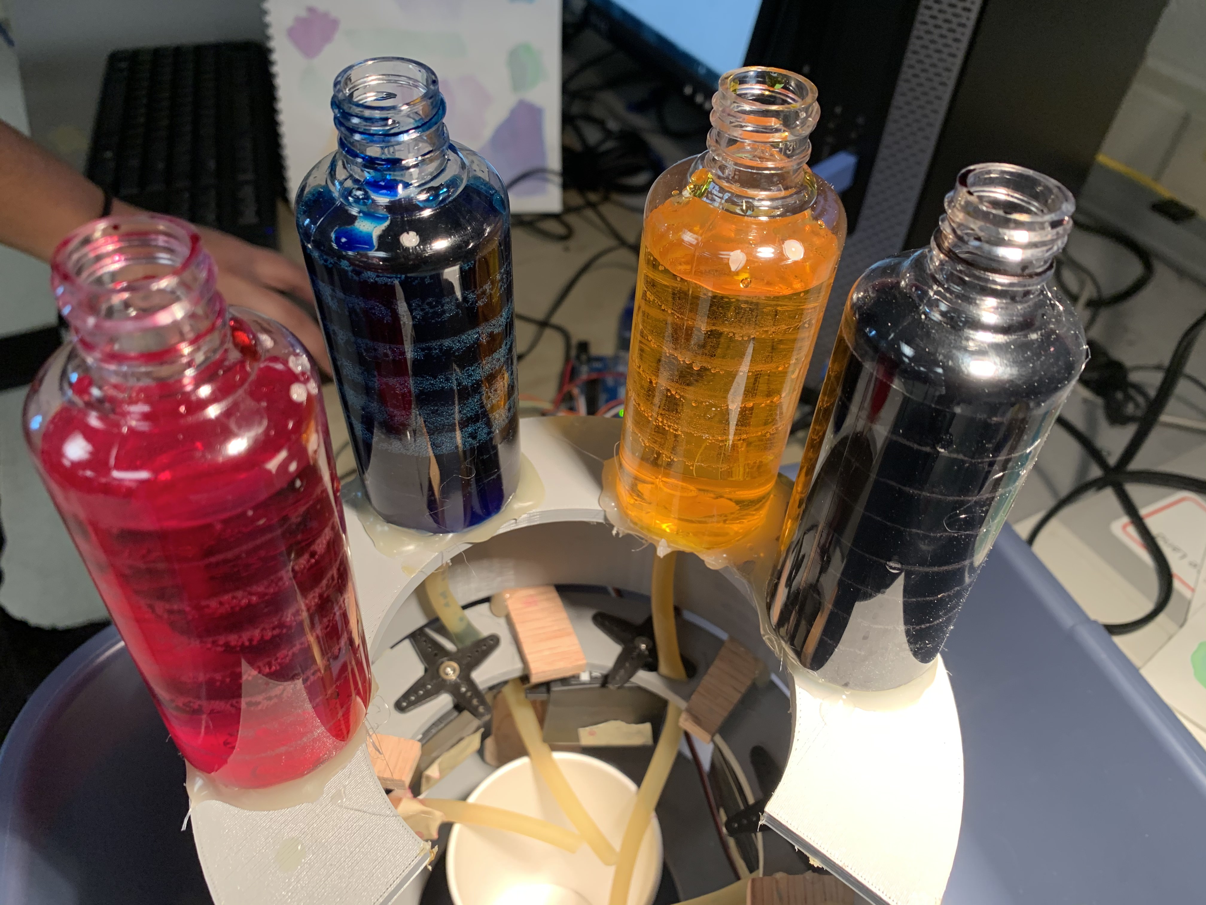
cyan, magenta, yellow, and black pigment they contain. We used the CMY primary colors because we were mixing pigment, and we decided to allow the user to pick a HEX value -- which are simply RGB values strung together in hexadecimal to make a 6-digit string -- because it would be an easier format for a user to enter. Thus, we needed to convert from HEX to CMYK.

cmyk image
Source


Very coincidentally, someone had already written a HEX to CMYK conversion in JavaScript. We used its logic to write our own HEX to CMYK conversion in C. Our conversion took a HEX code as character array of length 6, pulled the RGB values from it, then converted those according to the referenced code.
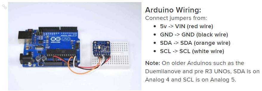
Color Sensing

The TCS34725 came with its own arduino source code and library. Here is a link to the original github repo. In this code, we took the example tcs34725.ino, renamed it COLORSENSOR.ino, and modified it to fit our needs.

The original code got the raw RGB values and also some extra calculations such as color temperature, which we removed. The color sensor raw outputs range from 0-65535. In order to make them usable RGB values, we divided the raw value by 256 to scale it to 0-255. However, this number usually ended up fairly small within the 0-255 range (generally under 30), so multiplied it by 10. Sometimes the “multiply by 10” put the value above 255. In this case, we did a second scale to the RGB values so the highest one is 255 and the rest are scaled down accordingly.

Once we had usable RGB values between 0-255, we converted the values float to integer. This integer was compared to the previous RGB values, which were saved in global variables. If the value is the same as the previous value, it will then convert those integer RGB values to hex and then put them into strings, which are concatenated and then sent serially to the PIC. If the values do not match the global variables, we set the current values to the global variables and begin the scan again. The requirement for the values to be matched allows for greater accuracy in which color is output.

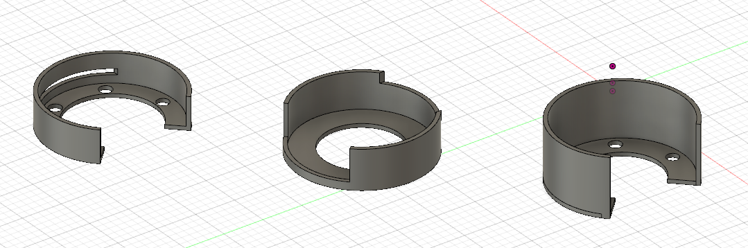
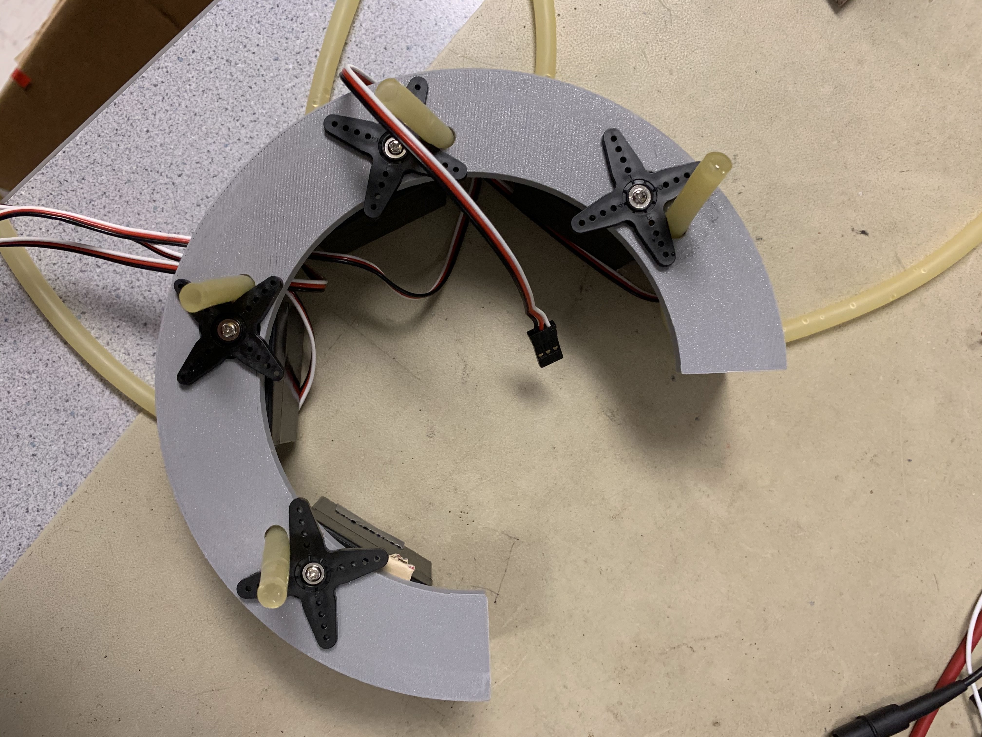
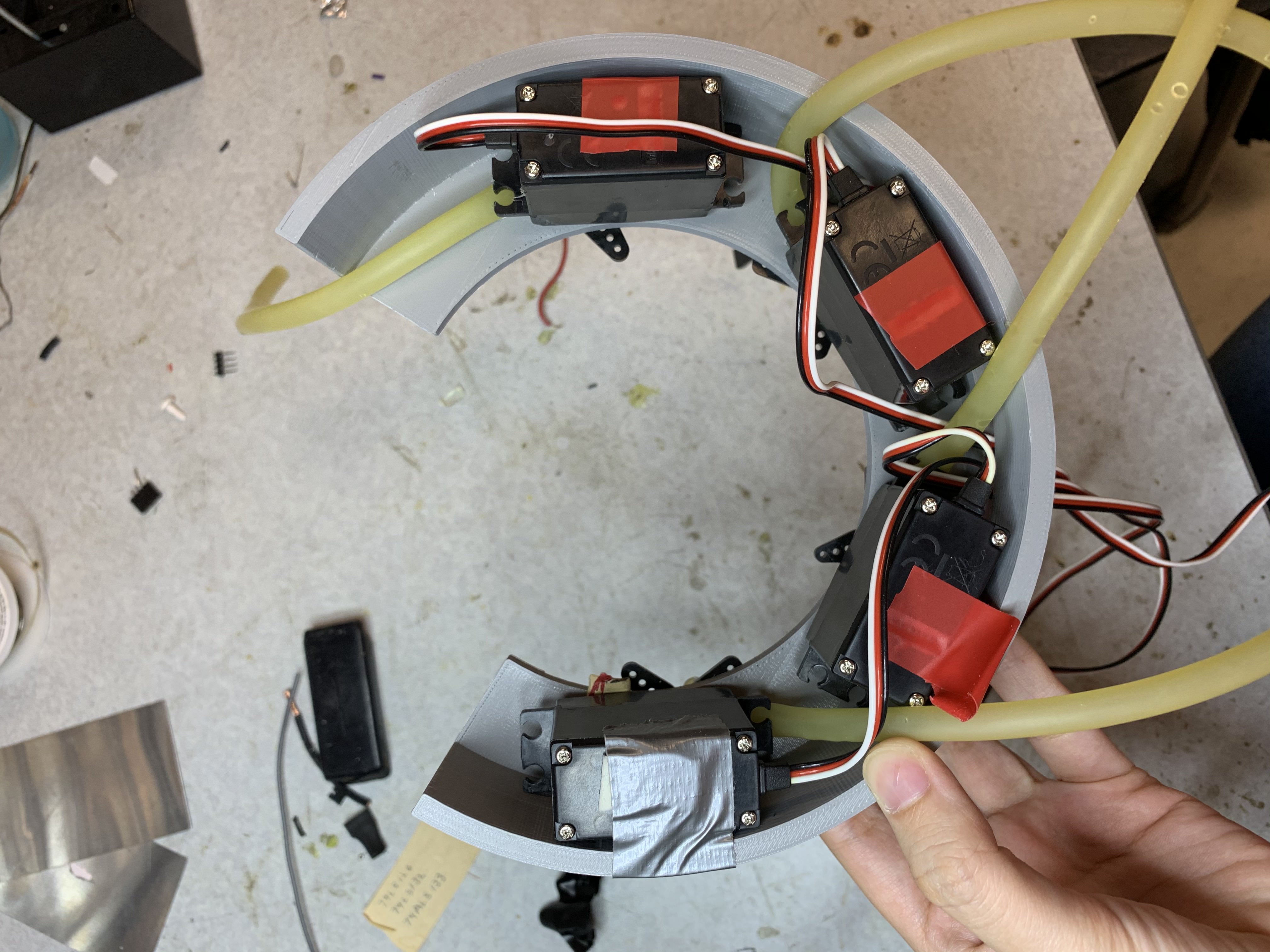
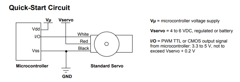
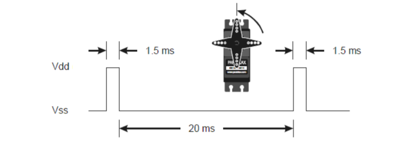
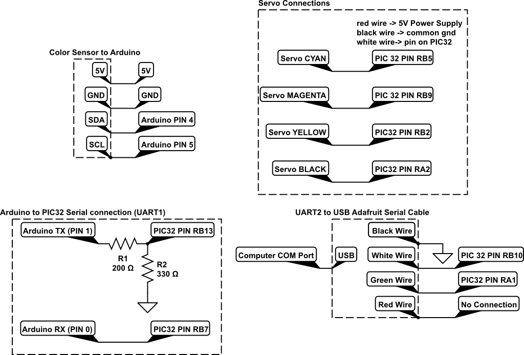
PWM and Servo Control

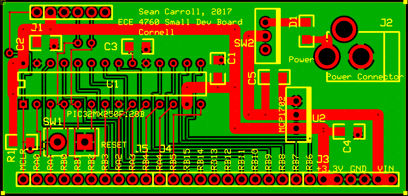
For this project, we utilized a singular timer with four different output compare units using it as a source. The four output compare units were wired to RB9, RB5, RB2, and RA2, each generating a PWM signal for 
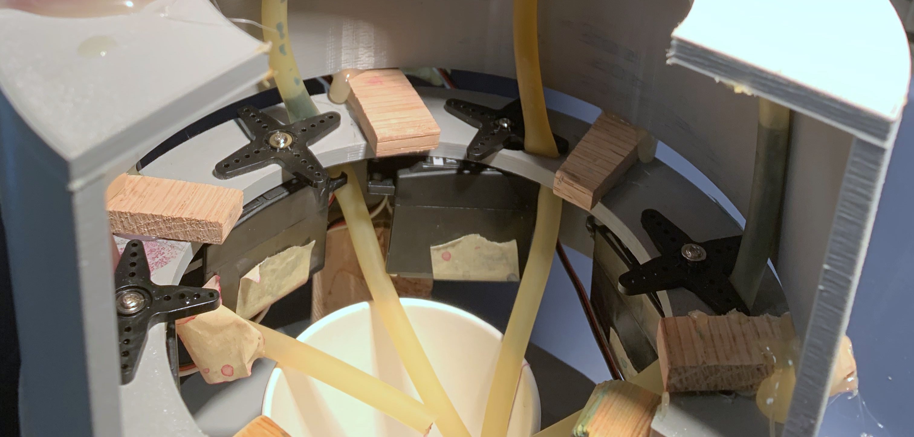
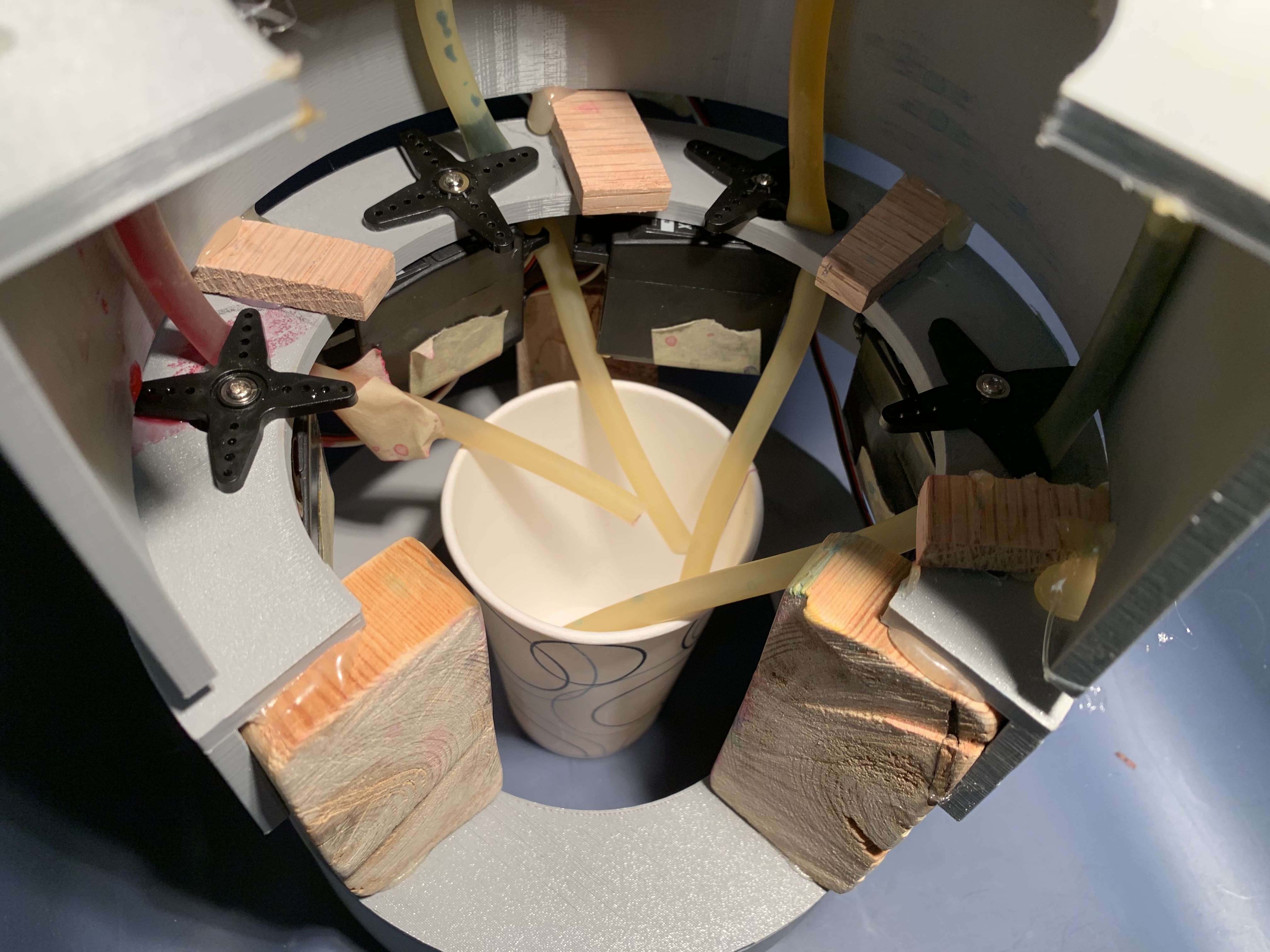
a different servo. Servos were initialized to a closed state based on how they had been mounted. Once ready to dispense the dye, we used the values from the CMYK conversion as timing for how long each servo should be open. We scaled the values, so the maximum time a servo could be open was one second and the minimum was ten milliseconds. To have each servo remain in a given position, we found that setting the corresponding duty cycle to zero worked. We were then able to target each servo individually, modifying the period and corresponding duty cycle. We created the timings by having the servo thread yield for the specified time as shown below.

              generate_period2 = (int)(((20.0 + 0.85) / 32.0) * 40000);
              pwm_on_time3 = (int)((0.85 / 32.0) * 40000);
              WritePeriod2(generate_period2);
              SetDCOC3PWM(pwm_on_time3);
              PT_YIELD_TIME_msec(10*error_m);
            
Additionally, to have the timer count for larger intervals, we increased the prescaler in the timer declaration.

              OpenTimer2(T2_ON | T2_SOURCE_INT | T2_PS_1_32, generate_period2);
            

Serial Communication

In order to implement two lines of serial communication on the PIC -- one to the computer for user input, and one to the Arduino to read the color sensor values -- we referenced the instructions on the class webpage. Using Protothreads 1.3.3, we used the main serial channel to communicate with the PC and the auxiliary serial channel to communicate with the Arduino. For the serial PC communication, we used a UART to USB serial cable, connecting RA1 to RX, RB10 to TX, and grounding both. Similarly, for the arduino, we connected RB13 to the arduino RX and RB7 to the arduino TX. To transmit and receive from the PIC32, we used the serial buffers for the main and auxiliary channels. To write, using the main as an example:

sprintf(PT_send_buffer, “hex #”); PT_SPAWN(pt, &pt_DMA_output, PT_DMA_PutSerialBuffer(&pt_DMA_output));

To read, using auxiliary as an example:

PT_SPAWN(pt, &pt_input_aux, PT_GetSerialBuffer_aux(&pt_input_aux)); sscanf(PT_term_buffer_aux, “%s”, &hex_value);

Please note that PT_term_buffer_aux is not originally defined in pt_1_3_3.h. This is something we defined based off of how PT_term_buffer was written. Our PuTTY output looked like this:
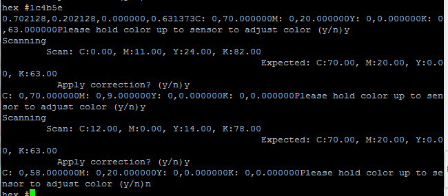
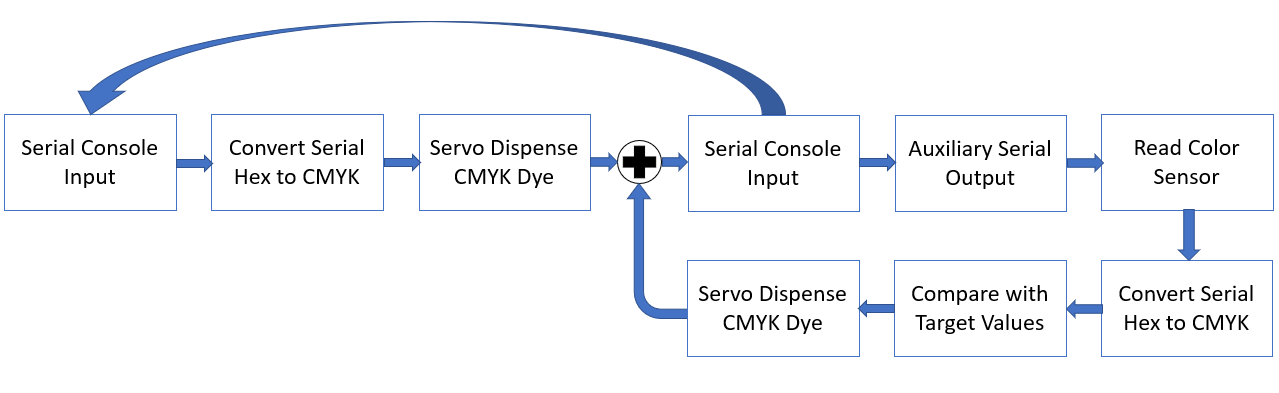
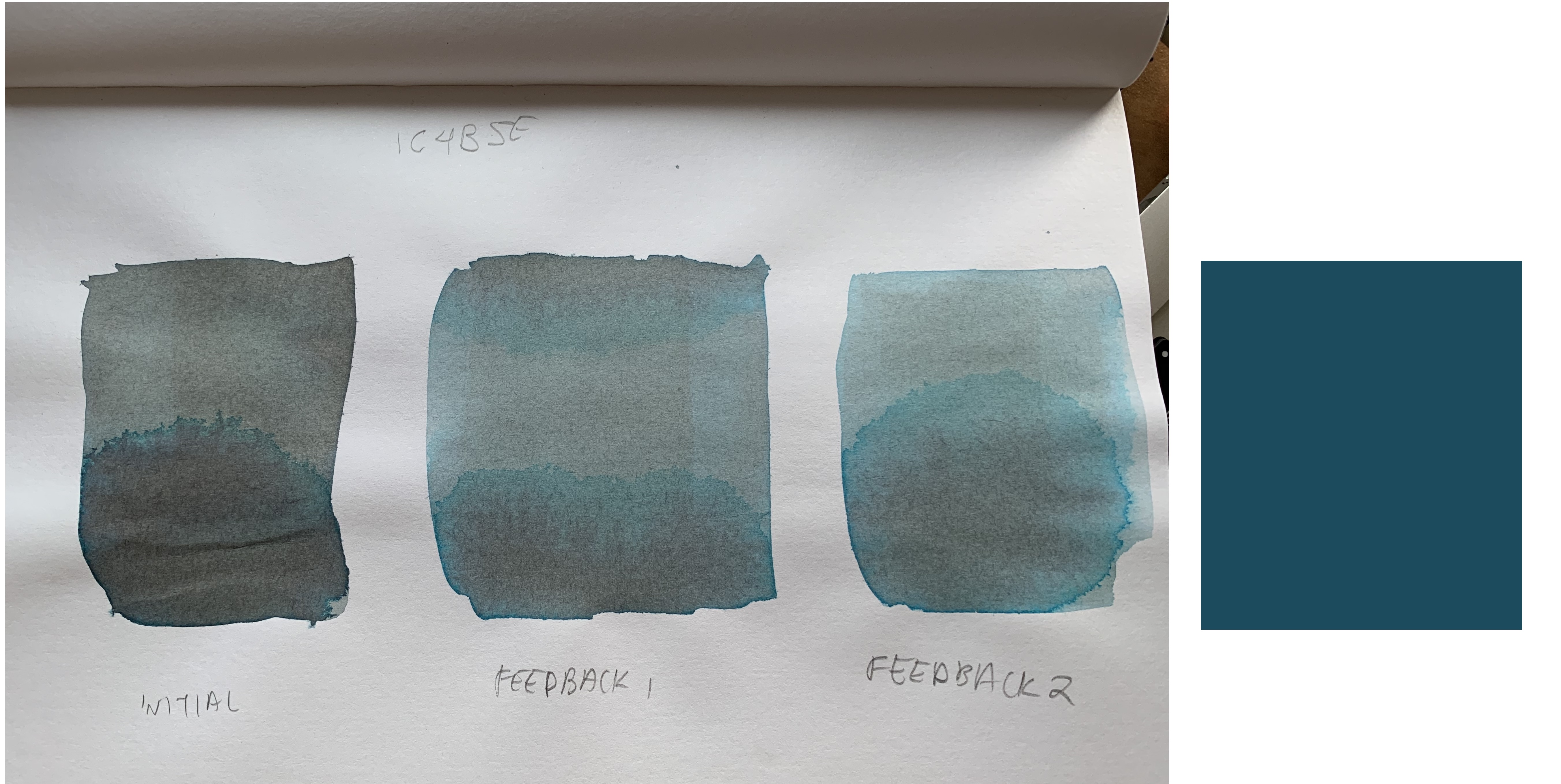
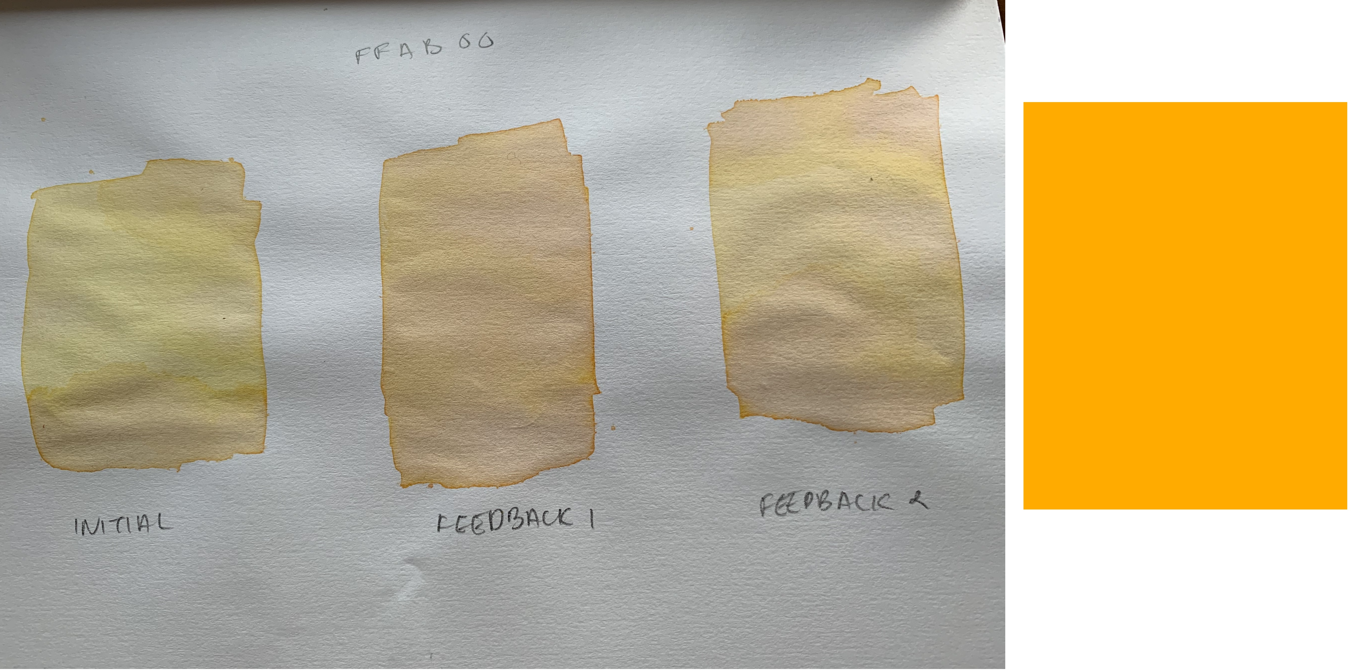
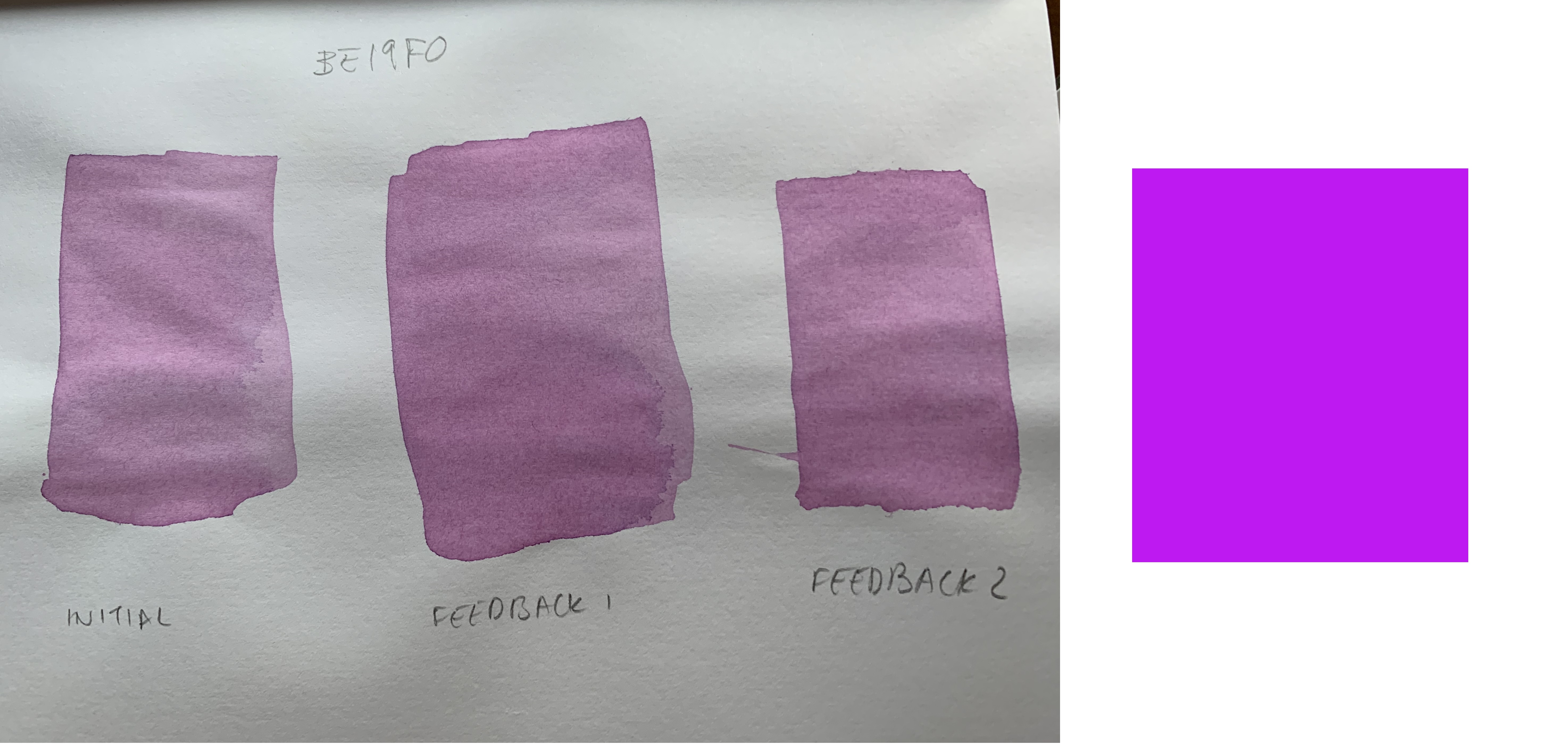
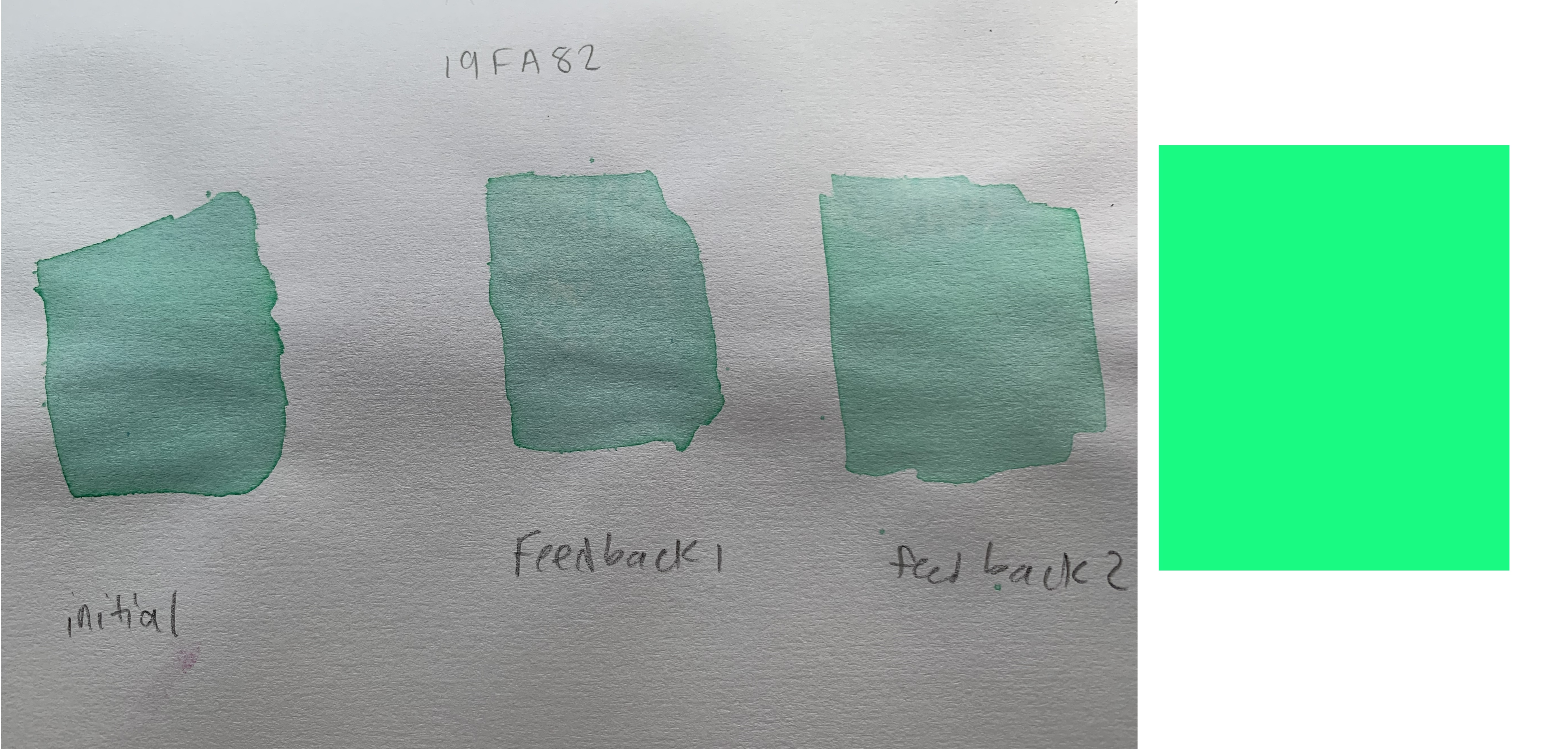
1c4b5e


Feedback Control

We opted to do user prompted feedback control due to the inconsistency of the color sensor. By prompting users if (1) they wanted to adjust t he color and (2) to hold a sample up to the color sensor, we could obtain a more accurate reading without having to handle the color sensor being splashed (if we had placed the sensor close to the mixture) and reflectance of the color sensor’s LED (if we had used a clear container for the mixture).

To perform feedback, we wrote a simple ready/request protocol, where the Arduino would initialize and waiting for a request from the PIC32. When a user requested a color adjustment, we would then write a request to the auxiliary serial buffer and then wait for Arduino. The Arduino would then read to color sensor, convert the value to hex, and write that to the serial buffer before going back to its ready state. The PIC32 would then use HEX to CMYK conversion and compare the sensor values with the expected color values.

We again prompted the user, displaying both the observed and expected values, asking the user if they wanted to proceed with an adjustment. If yes, then we observed which of the expected color channels (CMY) were zero, because at most two are nonzero at any one time, and calculated additive adjustments for the nonzero channels as shown below. For the black channel, we only checked if the observed color was too bright, and then added more pigment if so. We then used the adjustment values to control the servo timings to dispense the appropriate amount of pigment for the adjustment.

              if(final_c < 5){ 
                if(y2 < final_y){
                  error_y = final_y - y2;
                  }
                if(m2 < final_m){
                  error_m=final_m - m2;
                }
              }


Aside: Color Sensor as Input

Although this did not make our final demo code due to time constraints, we did write code to use the color sensor as an input option in addition to the terminal hex value. The idea behind this was to be able to replicate the colors of specific objects. The code functioned similarly to the user prompted feedback control in that the system would ask the user whether they would want to input a hex code or scan an object. This version was not included in our demo due to inaccuracy of the color sensor on objects with reflective surfaces and variable ambient lighting conditions.

Results of Design

The final results of the project may be seen in our demo video:


Speed

The servos’ response to the user’s hex input is very fast, which you can see here (since it was too fast to be caught in the demo):


The scanning, on the other hand, takes a variable amount of time. In order to maintain accuracy, the arduino will only send color data if the color sensor detects the same RGB values twice in a row. While this generally means that the scan will be accurate, it also means that slight physical movements of the color sensor or surrounding light will cause the scanning to take a longer amount of time.

Accuracy

To the naked eye, our colors -- for the most part -- look approximately correct. There are slight aberrations due to the cheap ink, which don’t correctly align with pure CMYK values, and misreadings with feedback. Misreads in feedback likely are a result of reading the color while the ink is still wet.

This is easier to see with some example tests. The leftmost image contains the initial color and two trials of feedback, and the rightmost image is the actual HEX color.

1C4B5E
Scan: #1C4B5E C M Y K
First Scan 70 20 0 63
Feedback 1 Scan 0 11 24 82
Feedback 1 Correction 70 9 0 0
Feedback 2 Scan 12 0 14 78
Feedback 2 Correction 58 20 0 0
For color #1C4B5E, which looks like a dark blue to the human eye, we can clearly see feedback demonstrated. In the color sensors’ first go, it created a color that was much too dark. In the first feedback scan, it noticed that there was much extra black. During the corrections, we can see that the color sensor does not add any more black, as there is already too much, and instead adds more cyan and magenta in order to correct the color.

FFAB00
Scan:
C M Y K
First Scan 0 32 100 0
Feedback 1 Scan 0 1 30 43
Feedback 1 Correction 0 31 70 0
Feedback 2 Scan 0 8 34 57
Feedback 2 Correction 0 24 66 0
In the color sensors first go, the color it made was slightly too yellow, so in the first feedback it added more magenta to compensate and make the color more orange. It also added more yellow to make it more pigmented. In the second time around, while there was more yellow and magenta, there still wasn’t as much pigment as the original color, so the color sensor added more.

BE19F0
Scan: #BE19F0 C M Y K
First Scan 20 89 0 5
Feedback 1 Scan 0 12 13 64
Feedback 1 Correction 20 77 0 0
Feedback 2 Scan 0 26 39 90
Feedback 2 Correction 20 63 0 0
To the naked eye, the three color swatches for this color look the same. This shows that the ratio of colors stayed consistent through the feedback runs. Looking at the PuTTY output, we can see that the color sensor was attempting to make each of the colors more saturated.

19FA82
Scan: #19FA82 C M Y K
First Scan 90 0 47 1
Feedback 1 Scan 43 0 20 60
Feedback 1 Correction 47 0 27 0
Feedback 2 Scan 26 0 21 43
Feedback 2 Correction 64 0 26 0
This is another case where the color sensor was trying to amp up the pigment during each feedback run. It is interesting to note in this case that it the color sensor seemed to see “less” cyan during the feedback 2 scan than the feedback 1 scan. This may be due to the fact that the color was still slightly wet on the paper when we scanned it, and we may have scanned a less dense part of the color.

Safety

Our project was safe on its own -- but a project involving lots of liquid in an electronics lab has the capability for mild disaster. In order to ensure that the liquid stayed away from electricity, we were careful about where we placed liquid. We always kept our project and any liquid in a Rubbermaid container so that any spills would be contained.

Usability

Our project by nature is accessible to people with colorblindness, because it is not necessary to distinguish colors visually in order to create a certain color.

The physical design of our project is somewhat inaccessible. Loading and removing the cup to catch ink, filling the containers, and ensuring the tubes don’t splatter everywhere requires dexterity that some people may not have. Even with small hands, interchanging the cups resulted in getting ink on one’s hands. To improve this in future iterations, we would put more thought into the mechanical design to be open and secure.

Intellectual Property

The Protothreads and Arduino libraries are not ours. Our header files for the PIC32 code were taken from Bruce Land's samples on the ECE 4760 course website, with some minor edits as necessary. The Arduino color sensor libraries are from Adafruit.

Conclusions

We were unsure that our project would actually function, as our initial plans changed and we ended up having to improvise a lot of aspects of the project. However, we were able to create an ink mixer that could successfully mix colors based on a hex input and respond successfully to open-loop feedback -- in that sense, our project met expectations.

We were forced to be adaptive with our design, since we initially proposed creating a paint mixer. However, we realized that the viscosity of paint presented many more mechanical challenges in dispensing and mixing the paint -- which were not our technical focus (as we were more interested in the color feedback), had a larger propensity for failure (due to a lot of moving parts), and were pushing the budget limit -- so we switched to working with inks. In the future, with more time to figure out a mechanical system, it would be fun to create a paint mixer -- but for the time given, it was more practical to create an ink mixer.

One issue we ran into was a lack of “true” primary colors. The inks we used were cheap printer inks, and their corresponding cyan, magenta, and yellow were not true to the actual cyan, magenta, and yellow colors.

In the future, we’d like to either 1) purchase better inks or 2) somehow compensate for the error in our color conversion. We considered trying to figure out how to convert from RGB to the slightly inaccurate CMYK, but did not do so due to time constraints -- and our results were approximately correct, anyway. We’d also like to do more tests with more highly concentrated colors, since we watered down our inks, and with more absorbent paper (like watercolor paper).

We were proactive in creating a mechanical design early, with the hopes of filling it nicely and having a polished product. After we changed designs, however, we had to improvise a lot and had a somewhat disheveled-looking end result. If we were to do it over again, we would ideally have knowledge of our full design before creating the model, so that we could make one that actually fit our mechanical design and was easily usable by the user.

In a similar aesthetic vein, we would also clean up the PuTTY output to be more visually appealing, or perhaps create a GUI that would allow the user to pick their color on a visual color picker rather than just entering the hex code.

Appendix A: Permissions

The group approves this report for inclusion on the course website. The group approves the video for inclusion on the course Youtube channel.

Appendis B: Schematics

circuitdiagram
Overall circuit diagram.


Appendix C: Budget

Component Quantity Vendor Total Price
Tubing - 3ft. 1 Amazon $6.39
Parallax Rotation Servos 4 Joe Skovira $59.96
CAD 1 Cornell Maker Space $0
CMYK Printer Ink 1 Amazon $16.13
Carry-On Containers 4 Amazon $5.72
Sean Carroll's Small Board 1 Bruce Land $4
White Board 1 Bruce Land $6
Power Supply 1 Bruce Land $5
PIC32 1 Bruce Land $5
Sockets 28 Bruce Land $1.40
Jumper 11 Bruce Land $0.10
Color Sensor 1 Adafruit $7.95
Arduino 1 Surplus - from Henri $0
Total $118.65


Appendix D: Commented Code

PIC32 Code:
  • happy_lil_mixer.c
  • port_expander_brl4.h - from Bruce Land
  • config_1_3_3.h - from Bruce Land, with edits
  • pt_cornell_1_3_3.h - from Bruce Land
  • Arduino Code:
  • COLORSENSOR.ino


  • Appendix E: Datasheets and References

  • Parallax Rotation Servo Datasheet
  • TCS34725 Color Sensor Datasheet
  • TCS34725 Github
  • Javascript HEX to CMYK conversion code
  • ECE 4760 Board Reference Page
  • UART Communication for PIC32


  • Appendix F: Work Distribution

    Although we have listed the person most responsible for a particular task, we helped each other on all tasks.
  • Brainstorming and design formation: Everybody
  • CAD: Priya
  • 3D Printing: Michael Xiao (ECE 4760 Fa18)
  • Servo Calibration: Michael
  • Serial Communication: Henri and Michael
  • Color Conversion: Henri
  • Color Sensor Testing: Priya
  • Feedback: Michael
  • Mechanical Assembly: Henri
  • Testing: Everybody
  • Hand Dying: Priya
  • Report: Everybody
  • Website: Henri