 |
|||
| by Henry Hsu (hmh6) and Oscar Ramirez (or16) | |||
|
[Introduction] [High Level Design] [Program/Hardware Design] [Results] [Analysis] [Parts Listing] [Code] [Schematics] |
|||
|
High Level Design The modified remote control vehicle we purchased had to have certain functionalities: 1. The user must still be able to "drive" it - after all, you don't just get into a car and let the car run. 2. The vehicle must never collide with any objects. 3. The vehicle must have its own power to detect "danger" if the driver cannot. 4. The vehicle must take a course of action since the human cannot be trusted. 5. This simulation vehicle must be implemented with a programmable Mega163. 6. The vehicle must stand on its own [i.e. be mobile].
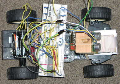
2. The vehicle never collides with any objects because power to the motors is cut off completely when you come within 4 feet of an object. At this time, the sensor is rotated to find the best possible path of "escape", and the car forces itself to drive in that direction (or reverse in the case where no path is greater than 4 ft.). 3. To detect this danger, we chose to use a DevanTech SRF04 Ultrasonic Range Finder. The means through which distance was found was through a pulsing methodology: a sonic pulse would be sent out from the SRF04 using an interrupt scheme from our Mega163, and then the time until the pulse returned to the SRF04 was measured. Using the speed of sound in air, the distance to the object could be determined from the time for the pulse to go to and from the object. THE SRF04 was mounted on a rotating motor that would be able to swing in both the left and right directions. In the case where a possible "danger" was detected, the SRF04 would swing left, detect "safety" distance there, swing right, detect "safety distance" on the right, and then allow the Mega163 to determine which had a better path of safety.
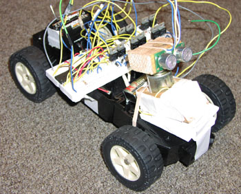
5. To implement these decisions and features in a R/C Car with a Mega163, the SRF04 needed to be attached to all 4 PORTs. PORT A was used to send the pulse, as well as recieve it. PORT B was attached as an output from the Mega163 to the motor control systems (for steering the car forward, back, left, and right), PORT C was used to control the motor that's used to rotate the sensor, and PORT D was an input from the user's remote. 6. The vehicle's mobility is due to the motor control system and the Mega163 being attached to an on-vehicle breadboard and being powered by standard 9V and AA batteries. The motor control systems were designed from H-Bridges, constructed using transistors found in lab.
|
|||