 |
|
| by Henry Hsu (hmh6) and Oscar Ramirez (or16) | |
|
[Introduction] [High Level Design] [Program/Hardware Design] [Results] [Analysis] [Parts Listing] [Code] [Schematics] |
|
|
Program Design
Program Design - our program design used an interrupt-driven scheme to poll object distance, calculate, and rationalize the best course of action. The vehicle itself was a state machine, having the states of "Normal Operation", "Detect Left Distance", "Detect Right Distance", "Center", and "Evasive Action" - all of which are fairly self explanatory states. The main() method of our program uses the interrupt to determine times at which to send a pulse through the range finder (30ms) and the times to detect the echo of the pulse recieved back (every 1ms). Since the speed of the vehicle was extremely slow, this was an adequate enough accuracy for the car to be able to determine a decently accurate reading of distance. Pulsing - Pulsing was done by raising the 0 bit of PORT A high and then switching it back low. This would send a supersonic wave out to "bounce" off any objects in the direction it was sent. A counter variable was incremented for every time period the pulse was not returned, and when the pulse was returned (PORTA.1 high being a recieved pulse) then the distance was calculated. The process is outlined as follows: Our state machine runs off timer0 with a period of about 30ms. The cycle
flows as follows:
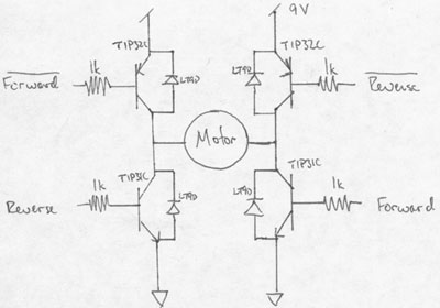
Normal Operation State - During this state, commands from the driver/user are merely passed to the motor scheme. Detect Distance Left State - The motor controls are shut down and the car is brought to a halt if the distance to an object in the front of the vehicle is less than ~4 ft. The motor attached to the sensor is operated to direct the sensor in the forward left direction to detect objects. Detect Distance Right State - the motor attached to the sensor is operated to direct the sensor in the forward right direction to detect objects. Center - The sensor is re-aligned in the forward direction for future detection of objects in front of the vehicle. Evade - the code calls to run the motors in the proper direction (forward left, forward right, or backwards) for 2 seconds in order to "evade" obstacles. Hardware Design Hardware Design - the Hardware we designed was used to "intercept" the user controls and then output our own controls to the vehicle. We therefore used the reciever/transmitter system that came with the R/C Humvee, and had to construct our own motor-driving system using H-bridges for bi-directionality in order to implement our "Safety Features". For additional info, see "Results". Motor System [H Bridge] - The 5V output from the PORT B pins did not have enough current to drive the motors to steer and drive the vehicle, or to rotate the sensor. For that reason we were forced to use self-made H-Bridges in order to drive the motors. Using two TIP32C (PNP) Transistors and two TIP31C (NPN) Transistors, along with diodes and resistors to draw current from the inputs, we constructed H-Bridges that could operate the motor in the forward and reverse directions using complementary inputs, as shown in the schematic below:
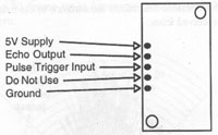
The same system was used for Left/Right, and the sensor motor's Left/Right. Unfortunately, this H-Bridge system was not as powerful as we had hoped. For this reason, we used a 9V battery to supply power to the motors, while still powering the Mega163 with 4 AA batteries. SRF04 Range Finder - We used a sonic range sensor pointed straight ahead to determine if there is an obstacle in front of the vehicle. The range finder has a detection cone of 30 degrees so we will be able to find objects at about 1.5 m at that are about 1.2 feet to our left, right, and above. The range finder is mounted to a block of wood which turns 30 degrees to the left and 30 degrees to the right. The detection system is mounted on top of the hummer and has an obstruction to prevent turns that are out of range. Upon detection of an object, the microcontroller puts 5V on one of the wires connected to the detection system H-bridge and 0V on the other wire. This difference in potential causes the sensor detection system to check left. About a half second later the microcontroller flips the polarity of the signal so that the detection system can check right. Finally in about 1 second the polarity is flipped again to return the sensor to center. Functionality of the range finder - The range finder takes as input a pulse with a period of 30ms and a pulse duration of 10 micro seconds. The output is a signal that is held high for a duration proportional to the distance. The Range Finder does not automatically detect distance; rather, the range finder had to be connected as follows:
Echo Output would send a signal to the Mega163 when a pulse was recieved back, while Pule Trigger Input took a signal from the Mega163 in order to send out the sonic pulse. Atmel Mega163 Connections - The Mega163 was removed from the STK200 board and placed on our bread board. We used the internal 1MHz clock (using fuse bits to select the internal clock during programming) and attached Vcc and ground to 4 AA batteries. We used a resistor to connect !RESET to Vcc as well. The PORT/PIN connections are as follows:
|
|