
Delivery System
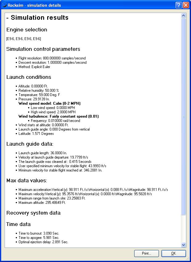
The delivery system was a single stage model rocket. The rocket was 3 inches in diameter and 4 feet tall. Due to the restrictions of launch site, the motor used was a cluster of Estes single-use E9 engines. The rocket was designed to reach an apogee altitude of approximately 300 feet.
At a preset altitude (programmed to be apogee detected by the microcontroller), the main chute will pop out. The parachute control system will then control the servo motor to guide the payload to a targeted landing site.
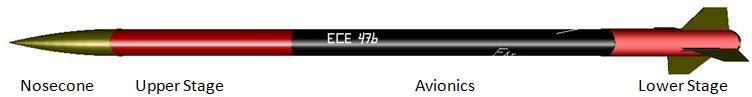
The rocket is divided into four sections. The nosecone will contain the calculated amount of sand to achieve the correct ratio of center of pressure and center of gravity. The upper stage houses the main chute, small heat shield, and its ejection charges. The avionics section contains all the electronics and mechanical control system. The lower stage includes the bottom airfame, motor assembly, launch lug/rail guide, and fin set. The sections are connected by medium size Kevlar shock cords.
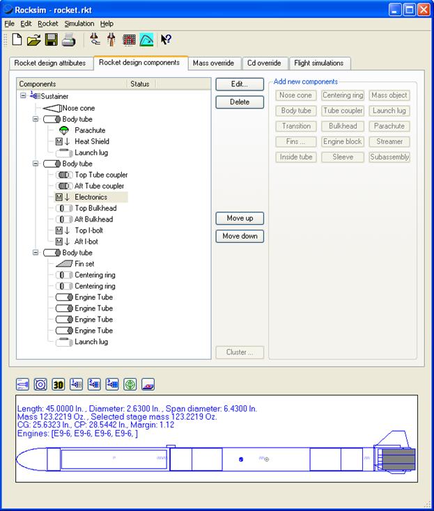
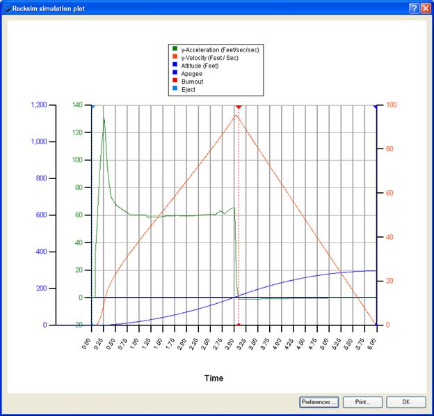
Using Apogee’s Rocksim program, the rocket was designed and built. The center of mass and overall mass was inputted but into the program after construction to obtain more accurate launch data. Click here for the Rocksim rocket design files and simulations. Click here (1 2 3 4) for the simulated launch data.
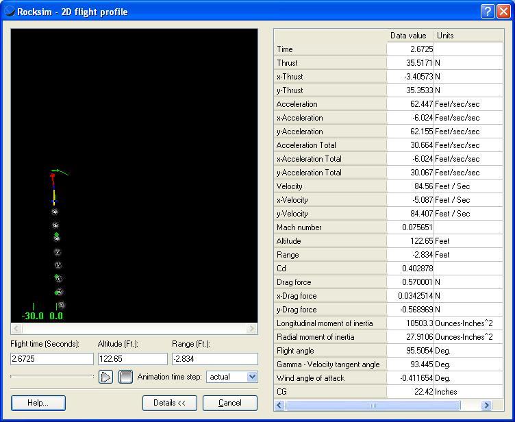
Guidance System
Avionics
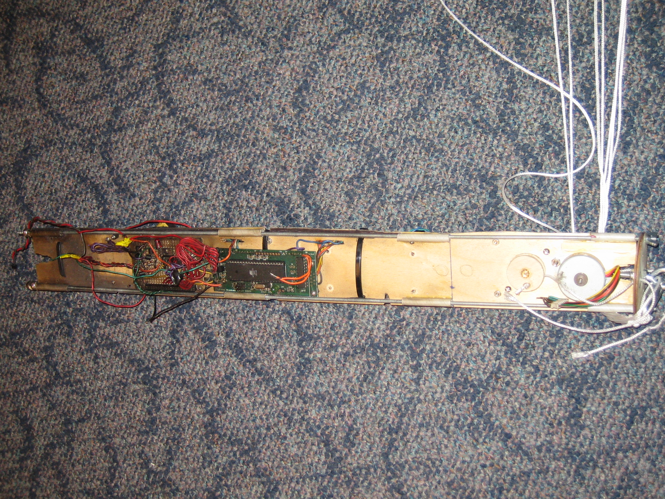
The Avionics houses all the electronic systems. The airframe is 3” in diameter and all electronics will be mounted on a tray (3/16 inch basswood). The tray slides on two parallel all-threads, which is bolted to the bulkhead at each end. The top bulkhead has two small holes in which two microbraid Kevlar shock cords (connected to the servo motor from the main chute canopy flaps) come out of. In addition, the bottom bulkhead also has an I-screw to mount the medium size Kevlar to absorb most of the weight (and shock). The medium size Kevlar will be connected directly to the main (center) airframe of the parachute. The micro braid will be loosely connected to the outer canopies of the parachute. There are also two bolts to which the ejection charge lines (primary and secondary) are connected.

Side A of the tray has the PC Board, Status Display and Power Board, SD Board, Isolated Timer Board, 9V Electronics Battery, and Left Canopy Stepper Motor. Side B of the tray has the Sensor Board, Motor Control Board, Isolated 9V Motor Battery, and Right Canopy Stepper Motor. We used autoCAD to plan the layout of the entire avionics section. This was an important step because everything had to fit into a 3 inch circular tube. And there were components that had to be mounted in certain orientation (such as the accelerometers and gyros). Click here to see the autoCAD design file
Professor Land’s PC Board houses the electronics for the ATMega32L. All the other boards are connected to the board’s I/O to interface with each other.
The Status Display and Power Board house the LCD to display the coordinates of the rocket relative to the landing site. The LCD was used mainly for debugging before flight; it was disabled and removed during the actual flight to save power and weight. There are several LED lights on this board. One set shows that the batteries are on (one for the motors and one for the other electronics). Another set shows the signal for safe to arm the ejection charges (both primary and secondary). Also there is a heart-beat LED to show the program is on as well as its current state. There is also 5V (LT1529-5) voltage regulator on this chip.
The SD Board houses the SD card holder (HR846CT) and the step-up/step-down circuit to properly interface with the SD card via SPI. Ultimately, this board was removed because we were not able to get the interface working completely. The 3.3V regulator was then no longer necessary either.
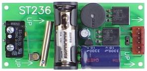
The Isolated Timer Board is a commercially off the shelf board (ST236 from Adept Rocketry) designed for rocketry application. It has a trigger mechanism to detect launch (and start a timer). It sends an eject the parachute signal at a preset time. For our launch demo, this timer was set to 9 seconds (the expected time to reach apogee was 5.981 seconds). This board has its own GP-23A battery, so it should be interference free from the other electronics. This is the backup ejection parachute firing mechanism.
The Sensor Board houses the three +/-8g accelerometers (MMA1220D), rate gyro (ADXRS150), and ADCs circuitry. The accelerometers are mounted orthogonal to each other to cover all three axes [picture]. The rate gyro is also mounted to detect the desired angular velocity in the XY plane. Two 8-bit ADCs are connects the sensors’ analog data to the input pins on the PC Board.
The Motor Control Board houses the opto- couplers (LTV847), darling arrays (ULN2003), and ejection charge MOSFETs (BUZ73). The opto-couplers isolate the high current ejection and the motor circuitry from the rest of the electronics. The darling array drivers the stepper motors using the isolated output generated from the PC Board. The MOSFETs uses the isolated output to short the 9V battery across the electrical match (Aerotech First Fire Igniter) to fire eject charge.
Accelerometers
The +/-8g accelerometers are provided by Freescale, which feature signal condition, a 4-pole low pass filter and temperature compensation, and a zero-g offset. The ones used were of the SOIC-16 packages which were easy to solder with the DIP adapter board. The operating voltage range was from 0 to 5V. And the output also span that range, so no step-up/step-down circuitry was necessary. The sensitivity is 250 mV/g, which delivered fair accuracy for our needs. The accelerometer interfaces with the PC Board ATMega32 via an 8-bit ADC.
Gyroscopes
We were able to obtain ADXRS150 evaluation boards from Analog Devices. The rate gyro can detect up to +/-150 degrees per second. The sensitivity is 12.5mV/degree/s. It was relatively easy to solder and fix to the electronics tray. And because it also had an operating voltage range from 0 to 5V, no additional circuitry was necessary other than the 8-bit ADC.
Stepper Motors
The two unipolar stepper motors are controlled via 4 pin connectors and driven using the ULN2003 high-voltage high-current Darlington array. A stepper motor turns when its leads (attached to electromagnets) are sequentially energized in an alternating pattern to turn the rotor (Stepper Motor Animation). The exact pattern is described in the appendix. The center-taps of each winding is connected to the 9V Isolated Battery. This is the same configuration found in a previous ECE 4760 project – Wall of Pong (Spring 2007).
Recovery System
Parafoil/Ram-Air Parachute
Several parachutes were constructed and tested. The requirement was for them was that they had to slow the rocket to an acceptable descent rate to insure the survival of the avionics and that it had to be steerable by the stepper motors. The circular parachute did not provide enough control unless the strings are pulled in several inches. Due to the restriction of the hardware, we can only do up to 2 inch pull.
We made our parafoil parachute based upon the directions found from this site.
A fancy complicated parafoil parachute was designed and sewed in the Martha Van Rennselaer Hall Design Studio Lab. It provided the good steering; however, for the rocket designed (too heavy), the descent rate was too fast. Making that parachute larger was not a feasible option because it has to be packed into the 3” diameter upper stage tube, which restricted it’s size.
Actual Parachute
The final parachute design was a simple large rectangular. It didn’t provide as much control as the parafoil parachute; however, it was somewhat steerable and provided acceptable descent rate.
Backup System
This is a single fault system. In the case of no parachute deployment, the rocket will come down ballistically; however, a triple redundant system was be used for the rocket. The software is designed to deploy parachute at apogee. A launch timer will also fire the parachute if apogee is not reached after 7 seconds. A completely isolated system (using the Adept ST623) will fire the parachute after 9 seconds.
Data Storage/Processor
The data were originally supposed to be written to the SD Card; however, due to some difficulties, we were never able to get it working completely. We ended up using the EE PROM of the MCU for data storage.
Miscellaneous
Safety Switches
There are two rotary switches (designed for rocketry application by Aerocon). They are externally mounted on the airframe of the avionics section. The rocket is unpowered until it is mounted on the launch pad. The power switch is first turned on. The power LED should come up and the heartbeat LED will be blinking at 1 Hz. The safe to arm LED is checked (no ejection charge signal) before turning the ejection charge switch to arm the rocket.
Isolation Considerations
All the noisy devices (motor and high current ejection charge) are isolated from the sensitive sensors. There are capacitors between power and signal lines to reduce noise.
Debug Tools
The LCD provided the x, y, and z positioning when we debugged and tested the hardware. When that was not sufficient, two signal lines (Rx and Tx) can be connected to the STK500 to use hyper-terminal for further debugging.
The USART interface was used for connecting the PC board to the STK-500 and computer to program the microcontroller and to analysis flight data after the launch. An LCD display (16 character by 2 rows) will be used to display the payload’s xyz coordinates and the distance to the launch site. The avionics body tube will have a 3.5” x 1” (radial inch) clear plastic window to look into for the LCD readings (and other LED status lights). Illustration below shows an example of the LCD character formatting.
|
X :
1 5
. 4
8
Y :
0 9
2 .
4 2
Z :
0 9
. 6
0
D :
1 0
4 .
7 6 |
Sample LCD Display
There will be LEDs on the Status Display Board. One will be the heart beat LED (at the rate of 1 blink/second). The power LED for each battery. Finally, there will be a safe to arm LED for each parachute’s ejection charge.
Difficulties
As mentioned above, soldering the 3-axis accelerometer (QFN and LGA) packages were extremely difficult. In the end we decided to use 3 single axis accelerometers (SOIC)
We had a lot of problems with the step-up/step-down circuit to properly interface with the SD card. We tried the two series diodes with a pull up resistor to 3.3V from the 5V MCU signal. We tried using two NPN emitter follower circuit where the first transistor inverted the signal and the second transistor revert it back but to 3.3V. We also tried the TTL two transistors in series push-pull configuration. All these circuit would work as long as the SD card is not plugged. Once the card is plugged in, the signal would fall below the 0.75*Vdd range for the proper high signal. One issue was that we were using the variable voltage power supply at the workstation (that used a transistor with a potentiometer configuration). Other times, we were just drawing too little or too much current. Our 3.3V regulator is a 3Amp, which should be sufficient for our applications. In the end, we figured out that the original schematic was that all the circuit was built around and soldered was incorrect. The VCC pin and one of the pin interfacing with the MCU. That mistake was corrected and the circuit was built; however, we didn’t have the time to mount and test the system prior to our launch demo.
We also had some problems just arranging the components on the solder boards so that everything can fit. At one point the LCD display, LED status, voltage regulator, and the SD card were all on the same board. It was just too crowded to scope and debug when a problem aroused. We solved this by using more small boards.
When we were debugging with hyper-terminal, we had some problems having the entire avionics section communicate to it. It took as awhile before we figured out the having just Rx and Tx was not enough. Because the avionics ran on the batteries, there was no common ground between our hardware and the SDK500.