
In-Lab Tests
We tested each sensor separately. It was hard to test the accelerometers so we used a simple test of measurements of +1g,-1g, and 0g. The 0g we assumed was center and calculated that ±1g was accurate to 1bit. To test to gyroscope we slowly rotated it and integrated the result. We marked a piece a paper and used a protractor to measure its accuracy. We found it to be quite accurate as show in table below:
| Measured Value(°) | Expected Value (°) | Error (%) |
| 0 | 0 | 0 |
| 24 | 25 | 4 |
| 62 | 64 | 3.13 |
| 121 | 117 | 3.3 |
| 145 | 144 | 0.69 |
| 170 | 173 | 1.76 |
Error =|Expected Value-Measured Value|/Expected value*100%
Mean of |Expected Value-Measured Value|=1.83°
Standard Deviation=1.47°
Testing results show that all electronics worked as planned. We attempted to test the electronics as much as possible in lab. We only had one shot to get a launch right; we devised many tests to prove that sections worked as well as an overall proper flow. This video shows the rocket waiting a minimum time and then firing an ejection charge as shown by the ammeter. The current was large enough and lasted long enough to theoretically fire a charge. This video demonstrates and explains the rocket going through all the motions of a launch. As shown in the video the rocket waits for an upward acceleration before entering flying. This change causes the heartbeat LED to change from slow to medium. After a minimum amount of time, the rocket goes into the falling state as shown by the fast blinking heartbeat LED. After a small delay waiting for the parachute to deploy, the motors turn to pull in the string on the parachute. Then one motor (depending on where the system thought it was) winds the string in 5 cycles and releases to turn. Finally, we tested the parachute first on a water bottle, and then on the actual rocket. As shown by this video, the parachute successfully opens and slows the decent of the rocket to a reasonable rate.
Error Analysis (Theoretical Accuracy)
Error from ADC: 5V/256 steps *1 step =±19.5mV
Accelerometer:
Error from ADC: =±0.0195V
*1g/256mV=±0.076g=2.45ft/s2
Maximum Sensor Output Error: ±12.5mV/g
Gyroscope:
Error from ADC: =±0.0195V *(1°/s)/12.5mV=±1.56°/s
Maximum Sensor Output Error: ±1.25mV/g
Launch Demo
During setup we had to make minor adjustments, such as reducing the length of the wire to light the engines in order to increase the amount of voltage dropped across the First Fire Igniter. Due to the wires’ length it had much more resistance than the four igniters in parallel. For safety we stood farther back then the minimum guideline of 50ft set by the FAA. We also launched it as a remote location in order to decrease the likelihood of causing damage to something or hurting someone in case of a failure. The rocket did not go as high as expected. We estimated that it went between 150 and 200 ft. This is significantly below simulated values. The parachute ejection charge did go off as the rocket started to fall. We believe the parachute never opened because it did not have enough time. The rocket only went up half as far as estimated and was not in the air as long as expected. We believe that it was the microcontroller that fired the ejection charge because a second ejection charge went off on the ground. This second ejection charge was about 9 seconds after the start of flight as the timer was set to. This means that the microcontroller fired the first charge.
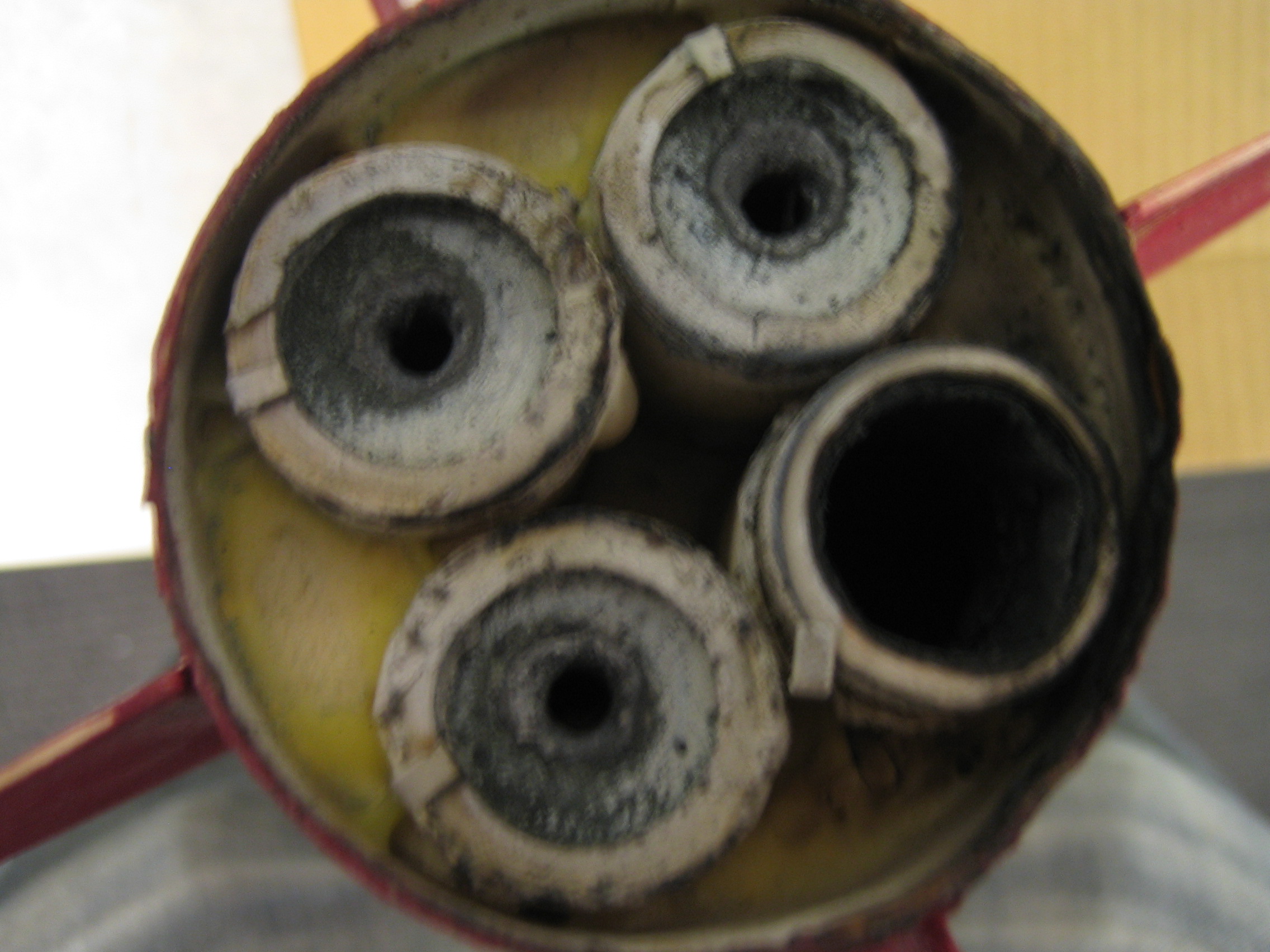
One major problem with the launch is that we believe one engine failed and fired into the rocket also. This would help explain many things that went wrong. It explains the fact that the rocket did not go as high as expected. Also there was visible evidence that inside the rocket the bulkhead endplate broke and burned. Also the electronics near the engines clearly burned along with the wood around it. This only happened on one side of the wood. Luckily, the LCD electronics was all that was affected. This plate also had the voltage regulators on it, but post launch testing proved these still functioned normally. One engine after flight looked different than the rest; the flame retardant nozzle was missing from that one particular engine. See pictures under media.
Due to an error we did not get video, but only sound. Also due to the rough landing the power supply to the microcontroller came loose. This was evident by a broken wire. We believe the data in APPENDIX was corrupted because of this. Due to the fact that the data started with 0’s and had some numbers at the end we think that once the rocket hit the ground it reset itself a few times as it did not have stable power supply. We can therefore not make any conclusions about the validity of our data. We do conclude that the microcontroller generally worked as it did fire the ejection charge on the parachute at the right time. As it waited a long time on the stand we conclude that it went through the state machine properly (WAITING->FLYING->FALLING) and could not have been due to random chance. This implies that the sensors worked and were giving reasonable values.
Raw Data
As can be seen in the bottom graph the raw data does not seem to be useful. It looks like much of the data was erased as it starts with a string of 0s. Also the times do no match expected times. Finally it seems we had a fixed point overflow error. The top graph shows this problem fixed for the x and y axis. The z axis data seems to be random so this was not adjusted. The integer overflow was only on data storage is it was greater than 2000ft. We thought 2000ft would be approximately an order of magnitude bigger than need to store data. This did not affect the internal representation of the data (floats). This data looks like a sensor is just staying at a fixed g as if the rocket is lying down. As explained before we believe this data is not accurate due to the microcontroller power supply coming loose on the ground. That would explain the 0’s to start. It also explains why the time numbers are so small. The amount of setup time was much greater than 23 seconds as critical time indicates. This means that parachute deployment time and pull in time are not valid either. Overall our data does not show anything. The visual of the parachute not ejecting till in the rocket was falling in the air and the second explosion to launch the parachute does indicate the program worked as expected. Also [this demo] shows the program working as expected in a laboratory test.
Raw
Data:
t =
[0 0 0 0 0 0 0 0 0 0 0 0 0 0 0 0 0 0 0 0 0 35 36 38 39 41 42 44 45 47 49
50 52 53 55 56 58 59 61 63 0 0 0 0 0 0 0 0 0 0 0 0 0 0 0 0 0 0 0 0 0 0 0
0 0 0 0 0 0 0 0 0 0 0 0 0 0 0 0 0 0 0 0 0 0 0 0 0 0 0 0 0 0 0 0 0 0 0 0
0 0 0 0 0 0 0 0 0 0 0 0 0 0 0 0 0 0 0 0 0 0 0 0 0 0 0 0]
xD
= [0 0 0 0 0 0 0 0 0 0 0 0 0 0 0 0 0 0 0 0 0 462 1180 2096 3299 4652
6215 8102 10073 12268 14886 17605 20622 24132 27669 31472 -29645 -25087
-20179 -14716 0 0 0 0 0 0 0 0 0 0 0 0 0 0 0 0 0 0 0 0 0 0 0 0 0 0 0 0 0
0 0 0 0 0 0 0 0 0 0 0 0 0 0 0 0 0 0 0 0 0 0 0 0 0 0 0 0 0 0 0 0 0 0 0 0
0 0 0 0 0 0 0 0 0 0 0 0 0 0 0 0 0 0 0 0 0 0]
yD
= [0 0 0 0 0 0 0 0 0 0 0 0 0 0 0 0 0 0 0 0 0 -6428 -8136 -9982 -11994
-13918 -15783 -17731 -19566 -21525 -23760 -25977 -28351 -31157 31462
28298 24609 20872 17160 13517 0 0 0 0 0 0 0 0 0 0 0 0 0 0 0 0 0 0 0 0 0
0 0 0 0 0 0 0 0 0 0 0 0 0 0 0 0 0 0 0 0 0 0 0 0 0 0 0 0 0 0 0 0 0 0 0 0
0 0 0 0 0 0 0 0 0 0 0 0 0 0 0 0 0 0 0 0 0 0 0 0 0 0 0 0 0 0]
zD
= [0 0 0 0 0 0 0 0 0 0 0 0 0 0 0 0 0 0 0 0 -18793 -25649 32511 24204
14325 4107 -7039 -19952 32519 18524 2576 -13337 -30172 16401 -2297
-21901 21759 377 -21898 18892 0 0 0 0 0 0 0 0 0 0 0 0 0 0 0 0 0 0 0 0 0
0 0 0 0 0 0 0 0 0 0 0 0 0 0 0 0 0 0 0 0 0 0 0 0 0 0 0 0 0 0 0 0 0 0 0 0
0 0 0 0 0 0 0 0 0 0 0 0 0 0 0 0 0 0 0 0 0 0 0 0 0 0 0 0 0 0]
critalT = [23 26 28 0]
Usability
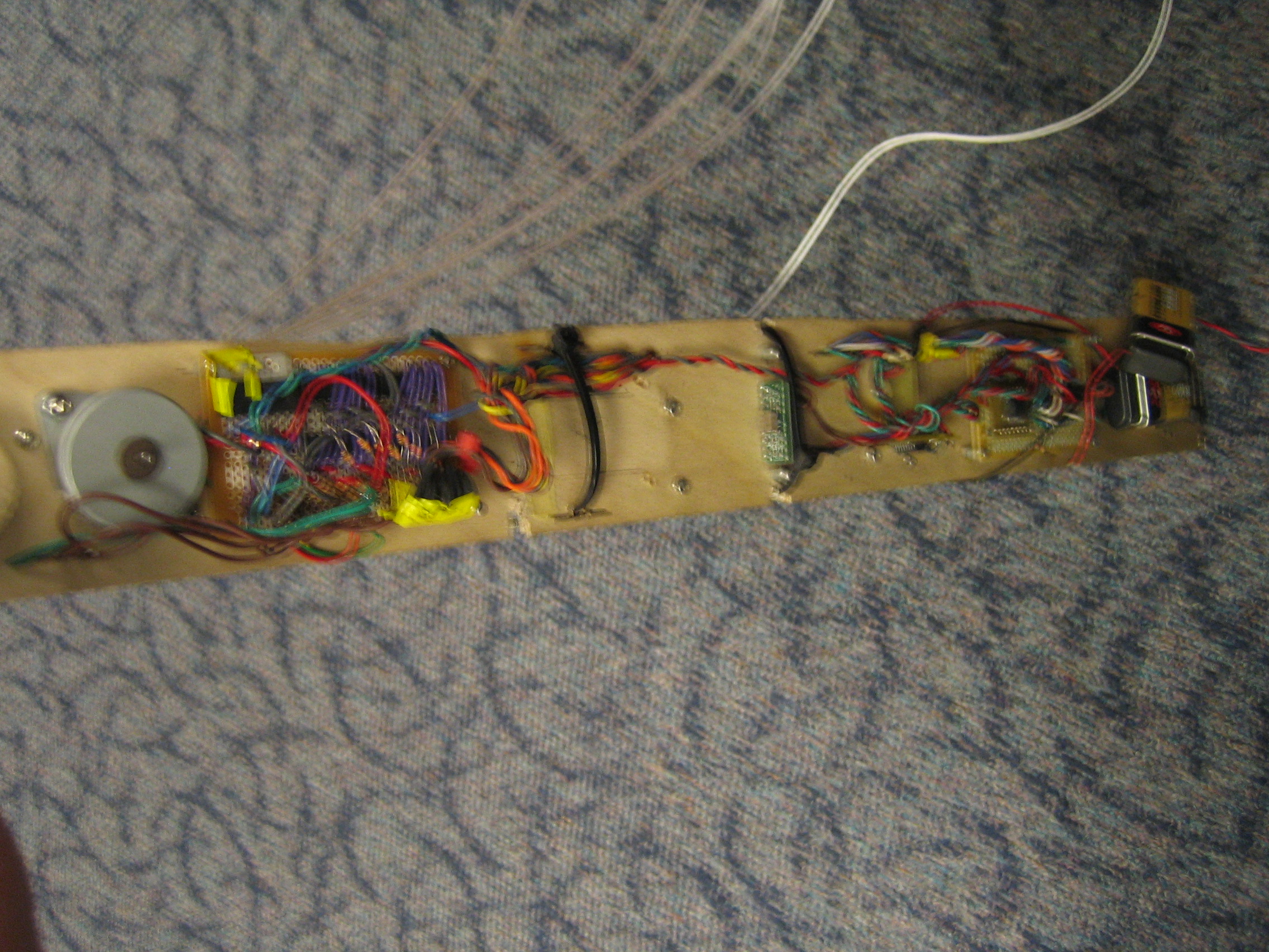
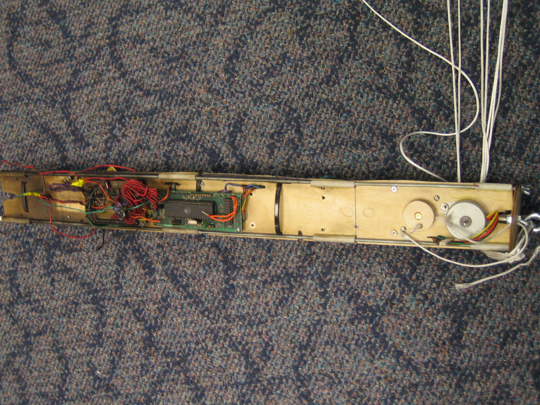
Due to the nature of our design, only those who are properly trained should attempt to build and repeat it. As we designed this system it was easy for use to use and understand. Before attempting to repeat or modify our experiment one should study our code and hardware thoroughly as an avoid any possible safety concerns. The schematics in appendix are correct and we include a fully commented version of the code in appendix. We also include a slightly modified, use at your own risk, code that should write to an SD card. There are other minor changes associated with this code, but can be used as a reference as to how to use the SD card as a data storage devise. Due to a wrong schematic we were unable to test this code. These pictures [I & II] show the layout we used. This is not the only possible layout and one may be able to reduce the weight of the electronics section via a more compact one