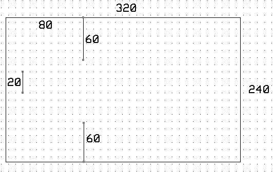
You will produce a game in which ball-like particles enter from one side of the screen. You must use a paddle to bounce the balls into collectors to get points. The paddle position will be controlled by an analog input. There will be a time limit to the game. Display will be on an 320x240 TFT LCD, with DMA sound effects.
The balls will follow standard billards-type dynamics, with zero friction between balls. An example of billard dynamics is shown below.
The sound must be produced through a DAC output using a DMA channel.
Procedure:
In this lab and every lab, make sure you are running Protothreads 1_2_2 or later.
There is a fixed point animation example on the Dev Board page, including forces for gravity and drag (video).
All TFT connections from lab 2 stay the same and are wired for you on the big board.
Most of the DAC connections stay the same, except as noted below.
Sound effects using DMA SPI:
The SPI DAC you will use is the MCP4822 as in Lab 2. But you will be using DMA to drive the SPI channel, so you need to modify the chip-select pin on SPI2 to use framed SPI. This mode allows the SPI controller to toggle the chip select line, implying that only one peripherial can be attached to that channel, but simplfying program logic. See section 23.3.6 in the reference manual.
Specifically, this feature allows a DMA channel to blast data out to a DAC or other fast device without using an ISR.
Get sound output by connecting the DAC output (DACA or DACB) to the speakers.
DMA setup:
--
The logic might be to set up a DMA channel hardware-triggered by a timer event, and possibly using auto-repeat.
See the first example on the SPI page for details about framed SPI, but note that this example, while framed, does not use DMA.
-- Use
a DMA memory-source (flash or RAM) corresponding to a table of voltages, or-ed with the DAC control word in the high-bits.
-- Use
as a DMA memory-destination the SPI transmit register.
--
The DMA could be operated one-shot for a short sound effect, or in auto-repeat mode for a longer signal.
The length of the longer signal could be based on a timed thread event.
Game Controller via ADC:
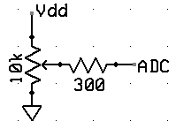
ADC input AN11 pin 24 using the potentiometer circuit shown below.
The game will be controlled by a trimpot potentiometer hooked
to an ADC input on the PIC32. Use the circuit to the left to make a user-variable voltage. The Development Board page shows how to set up the A/D converter to read a voltage in a thread. The example reads the AN11 analog input and draws the voltage on the TFT.
Trimpot schematic: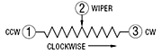 bottom view:
  image:
Dynamics:
You are going to be programming in the equations of motion for the balls. Remember that the video coordinate system has x increasing to the right and y increasing downward. We will step the billards system forward in time by calculating the total change in velocity from a collision, without worrying exactly how forces change the velocity.
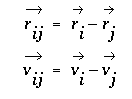
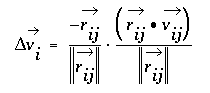
The change in velocity during impact can be derived for frictionless balls of equal mass by noting that the the impact force must act in a direction parallel to the line connecting the centers of the two impacting balls. The change in velocity must be parallel to the connecting line also, with the velocity component parallel to the line having its sign reversed by the collision and the velocity component perpendicular to the line unchanged. Projecting the initial velocity onto the line connecting the centers, negating the result, and resolving it back into x and y velocity components gives the velocity change. If i and j are the indices of the colliding balls, define:
then delta v for ball i is given by the following where the right-most term represents the projection of the velocity onto the line and the other term converts the projection back to x,y coordinates.
The calculation procedure for each time step is:
For each ball i from 1 to n

        For each ball j from i+1 to n

          Compute approximate rij by checking:

           if  Δx and Δy are both less than 4

            if (||rij||2 less than (2*(ballRadius))2 and hitCounteri is zero)

              Compute vij

              Compute Δvi

              Add Δvi to vi

              Subtract Δvi from vj

              Set hitCounteri big enough to avoid particle capture

            elseif (hitCounteri>0)

              decrement hitCounteri

            endif

           endif

        endfor

      endfor
rij|| (too slow). Compare the squares.rij||2 you need to be careful not to divide by zero (causes reset). A low ||rij||2 implies a head-on collision, rij||2 <1, just switch the velocities of the two balls. Otherwise, do the divide, perhaps by table-lookup.Δvi from any collision is applied for that ball), simulate friction between the ball and table by makingvx(t+dt)=vx(t)-vx*drag and vy(t+dt)=vy-vy*drag
The drag should be small, perhaps drag=0.001 ( but converted to fixed notation).x(t+dt)=x(t)+vx*dt and y(t+dt)=y(t)+vy*dtClearly, v and x all need initial conditions, which you will set, according the specifications below. It is doubtful that you will have enough time between frames to do all of the calculations in floating point. I suggest using 32 bit, signed numbers with the binary point set at the 16-bit boundary. I also suggest scaling velocity so that you can make dt=1, thereby avoiding a multiply. You can think of this as: (1) Units of distance are PIXELS, (2) Units of velocity are PIXELS/FRAME. As examples, any of the NTSC particle systems are done with fixed point numbers.
The previous analysis is adapted from: Studies in Molecular Dynamics. I. General Method, by B. Alder and T. Wainwright,
Journal of Chemical Physics, Vol 31 #2, Aug 1959, pp 459-466. See also Hard-Sphere molecular dynamics.
One final project in 2005 used a different scheme to calculate collisions.
You will need your digital camera to document your project.
Results:
2011: video Note that this is a different game using a television for display.
2014: video Note that this is a different game using a television for display: Shiva Rajagopal and Richard Quan
2016: video On TFT
Week one required checkpoint
By the end of lab session in week one of the lab you must have ONE of the following:
Week two required checkpoint
By the end of lab session in week two of the lab you must have TWO of the following:
Week three Assignment
Write a program in C using ProtoThreads with these specifications:
When you demonstrate the program to a staff member, you should play the game.
At no time during the demo should you need to press RESET.
Your written lab report should include the sections mentioned in the policy page, and :