Cornell University ECE4760
Direct Memory Access
PIC32MX250F128B
DMA on PIC32
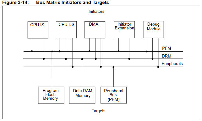
DMA uses memory controllers separate from the CPU to accelerate data movment between memory locations, or between peripherials and memory. The PIC32 has 4 DMA controllers which can stream an agregate of about 3.2 megabytes/sec without affecting CPU performance, in many cases. There are a huge number of options available to set up a DMA transfer. You can think of a DMA channel controller as a separate, programmable, processor with the main job of moving data. Memory on the PIC32MX series is arranged as a bus matrix with five memory bus control masters and three memory bus targets accessed by the masters see (Refence Manual chapter 3, section 3.5).
You can think of a DMA channel as separate hardware for doing a very flexible memory copy operation, triggered by any hardware event. Since peripherial data registers (e.g. ADC, SPI, timers) are memory-mapped, data can be moved to/from any peripherial to memory. Since the peripherial control registers are memory mapped, any peripherial can be used to control another peripherial, although a serial DMA machine or DMA channel chaining may be necessary to do carry out some operations. If a peripherial generates a hardware event (interrupt request) then controlling another peripherial can be done with one DMA operation. For instance, the existing PIC32 hardware allows you to trigger an ADC conversion from timer 3, but not timers 1, 2, 4, or 5. Using DMA you could trigger from any timer using no ISR and zero CPU cycles. More on this lower in the page.
The following material may help in understanding DMA (simplified from Reference Manual chapter 31).
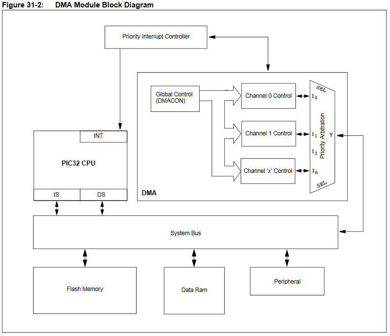
Figure 31-2 shows the conceptual layout of the cpu and DMA.
The cpu instruction and data masters as well at the DMA controller can each initiate data moves in
program flash memory, data ram, and peripheral register targets. (e.g. RAM to i/o port, or ADC to RAM, or flash to DAC)
Terminology for operational modes of the DMA Controller:
• Event -- Any system event that can initiate or abort a DMA transfer.
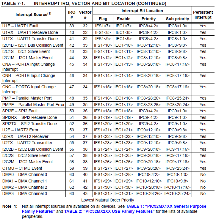
Any interrupt source can act as a DMA event -- but does not require that the interrupt be taken.
For a list of interrupt source names, open this and search for /* IRQ Numbers */
• Transaction -- A single word transfer (up to 4 bytes), consisting of read and write operations
• Cell Transfer -- The data transferred when a DMA channel has a transfer initiated by an single event.
The channel then waits for another event.
A cell transfer is comprised of one or more transactions.
Max cell size is 65,535 bytes transferred on an event.
• Block Transfer -- All of the data transferred when a channel is enabled.
A block transfer is comprised of one or more cell transfers.
Max block size is 65,535 bytes.
The channel remains enabled until the DMA channel has transferred the larger of source or destination sizes (i.e., block transfer is complete).
If auto-enable is turned on, then the block transfer repeats.
When the channel is disabled, further transfers will be prohibited until the channel is re-enabled.
DMA operating modes:
• Basic Transfer mode -- Copy memory to memory (but note that SFR are memory mapped so any peripheral can be read/written)
For example: ADC to RAM can be enabled to send data at a rate determined by a timer, but with NO ISR.
Timer3 triggers ADC directly (no ISR), then the ADC complete signal triggers a cell-transfer on a DMA channel with a RAM target.
• Pattern Match mode -- Copy memory to memory until a bit-match occurs between the transfered data and a template.
For example: copy a character array (string) to the USART until a NULL byte (end-of-string) is detected.
• Channel Chaining mode -- The end of one DMA channel operation triggers another DMA channel.
For example:
Use DMA channel 0 ADC to RAM buffer 0 for FFT,
then chain to channel 1 to record ADC to RAM buffer 1 without missing an ADC sample,
then chain back to channel 0 when buffer 1 is full.
• Channel Auto-Enable mode -- Hardware auto-looping over the source/destination memory locations.
Block transfer complete, or pattern match detect conditions do not disable the channel.
• Special Function Module (SFM) mode: Byte/bit reordering and LFSR CRC -- Cyclic redundacy check during a transfer. (see Chapter 31, section 31.3.5)
More details are in one of the examples below.
These operation modes are not mutually exclusive, but can be simultaneously operational.
For example, the DMA controller can perform CRC calculation, using chained channels, and terminating the transfer upon a pattern match.
A cell transfer is initiated in one of two ways:
• Software can initiate a cell transfer, but don't do this. If you use software to start every cell transfer, you are mostly defeating the benefits of DMA.
HOWEVER: Software can be used to initiate a block transfer. For long blocks, like sounds or strings, this is an efficient use of the CPU.
The protothreads routine PT_DMA_PutSerialBuffer starts a block transfer by enabling a DMA channel.
Each cell transfer after the first one is triggered by a USART empty event.
See protohreads header code, in the code search for #ifdef use_uart_serial
• Interrupt event occurs on the device that matches the start intrrupt source selected for the DMA channel, but with no ISR. The user can select any interrupt on the device to start a DMA cell transfer. The DMA Controller maintains its own flags for detecting the start and abort IRQ in the system and is completely independent of the INT Controller. The corresponding IRQ does not have to be enabled before a transfer can take place, nor cleared at the end of a DMA transfer. After the start or abort IRQ system events are triggered, they will be detected automatically by the DMA controller internal logic, without the need for user intervention.
A DMA transfer can be stopped by:
• Manually writing the channel abort command.
• A pattern match occurs, assuming pattern match is enabled, and provided that Channel Auto-Enable mode bit is not set.
A pattern match is treated the same way as a block transfer complete,
• Interrupt event occurs on the device that matches the selected channel abort event source.
• Detection of an address error
• A block transfer completes and the Channel Auto-Enable mode is not set.
DMA generated interrupts
• Error interrupts. This event occurs when there is an address error occurred during the channel transfer operation.
• Abort interrupts. This event occurs when a DMA channel transfer gets aborted because of a system interrupt matching the selected event, and when the abort interrupt request is enabled.
• Block complete interrupts. This event occurs when a DMA channel block transfer is completed.
• Cell complete interrupts. This event occurs when a DMA channel cell transfer is completed.
• Source Address Pointer activity interrupts. Either when the Channel Source Pointer reached the end of the source, or when the Channel Source Pointer reached midpoint of the source.
• Destination Address Pointer activity interrupts. Either when the Channel Destination Pointer reached the end of the destination, or when the Channel Destination Pointer
reached midpoint of the destination.
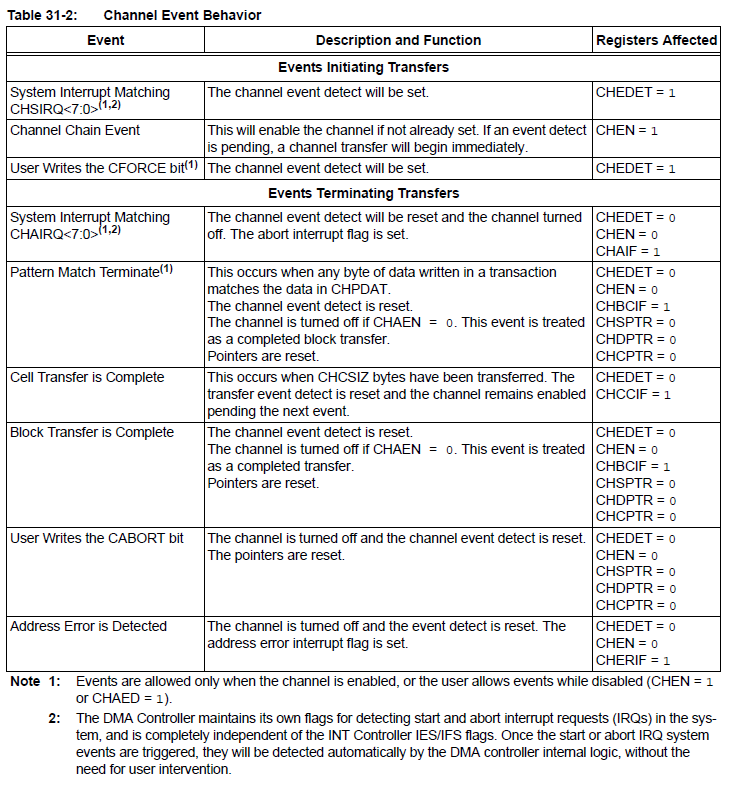
Channel Control Events
Examples
- DMA connection between peripherials for control
Since all peripherial control registers are memory mapped, DMA can be set up to alllow any peripherial to be used to control another peripherial, although a serial DMA machine or DMA channel chaining may be necessary to do carry out some operations. If a peripherial generates a hardware event (interrupt request) then controlling another peripherial can be done with one DMA operation. For instance, the existing PIC32 hardware allows you to trigger an ADC conversion from timer 3, but not timers 1, 2, 4, or 5. Using DMA you could trigger from any timer using no ISR and zero CPU cycles.
--
An example code triggers an ADC conversion on a timer 2 time-out event (interrupt flag, but no ISR) by using a DMA0 block to directly set the ADC start-conversion bit, triggered by the timer interrupt flag (Timer2 IRQ). A second DMA1 block is triggered to transfer one short-int to memory for every ADC-done event (ADC IRQ) until 256 values have been transfered. Main sends the 256 values to the SPI DAC. Sync between the DMA transfer and main is maintained by setting the DMA1 enable flag, then checking to see when it is clear.
- DMA to SPI: This DMA demo code should not be used as a starting point for anything, except understanding the minimum requirements for using a DMA channel! It does NOT include TFT support, Protothreads support, or port expander support! It merely opens a DMA channel, an SPI channel, and a timer. It explicitly sets up the system frequencies, which are done for you in Protothreads. All it does is transfer an array to the spi port to run a SPI DAC, and it toggles an i/o pin in main to measure perfromance (which you do NOT want). The SPI channel is running at 20 MHz bit-rate, the fastest the DAC can go. Since the DAC requires 16-bits (4 command, 12 data), and each bit takes two machine cycles (at 40 MHz main clock), the fastest the device could possibly run is 32 cycles on the timer2 timeout DAC cell-transfer event trigger. At 40 cycles (1 MHz sample rate) the system is stable, with a 256 point table yielding 3.81 KHz (expected is 1MHz/256 =3906) and full amplitude (implies no linear bandwidth limit). The slew-rate limited (non-linear), analog settling time of the DAC is 4 to 5 microseconds for a full amplitude (0 to 0xfff) step. Smaller steps (like a sine wave) settle more quickly.
With a 40 MHz system clock, the i/o pin in main toggles at 6.66 MHz (loop time of 6 cycles), independent of the state of the DMA channel. This implies no CPU performance hit from using DMA.
The main loop:
while(1) { mPORTAToggleBits(BIT_0); }
compiles to (to see this for your code: menu item Window>Debugging>Output>Diassembly)
9D003EB8 3C03BF88 LUI V1, -16504
9D003EBC AC62603C SW V0, 24636(V1)
9D003EC0 0B400FAF J 0x9D003EBC
9D003EC4 00000000 NOP
These instructions plausibly could execute in 6 cycles, depending on cache speed and branch overhead.
- DMA SPI to two DAC channels: Operating both DAC channels (DACA, DACB) is possible by building one large table which includes both channel signals in alternating table entries. All even-index table entries go to one DAC channel, all odd-index table entries to the other. The one DMA channel just cycles through all the entries. The synthesis sample rate is cut in half, but with the timer event set to 100 cycles (400 KHz), the sample rate on each channel is still 200 KHz. Code.
- Chaining Channels: This example code chains DMA channel 1 to DMA channel 0, so that when DMA0 finishes a block transfer, DMA1 is triggered to start a block transfer.DMA0 sends the sine wave. At the end of one sine cycle (block transfer), DMA1 sends a square wave cycle.
- Chain by cell-event: This contorted example uses DMA0 channel to trigger a DMA2 cell transfer after each cell transfer in DMA0. The DMA0 interrupt flag which is set by the cell transfer end-event is not auto-cleared, unlike every other interrupt flag used by a DMA channel. Channel DMA1 is used to clear the flag after each event by writing directly to the DMA0 control block when triggered by the DMA0 cell transfer end-event. Set up:
- Open DMA0, DMA1 and DMA2 in auto mode.
- Set DMA0 and DMA2 to transfer whatever data you want to arbitrary destinations,
in this case port A and port B.
- Set DMA1 to transfer two zero bytes to DCH0INT, the control register that has the flags for DMA0.
This resets the cell transfer interrupt flag, which is not done automatically for this IRQ source.
Note that there is no actual ISR in this program.
- Set DMA0 to trigger a cell transfer on a timer interrupt event.
This sets the square wave frequency, minimum timer interval is around 30 cycles.
- Set DMA1 and DMA2 to trigger a cell transfer on a DMA0 interrupt event.
This requires enabling the cell-transfer-done flag for DMA0.
And clearing the flag using DMA1
- Enable all the channels.
The example transfers square wave samples to two output ports
every 40 timer counts (1 microSec).
The wave sent by DMA2 is half the frequency of that sent by DMA0.
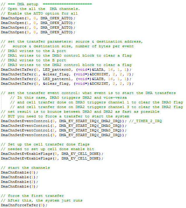
- Two Channel ping-pong: This example uses the cell-transfer-done interrrupt flag on DMA0 to trigger DMA2, and the cell-transfer-done interrrupt flag on DMA2 to trigger DMA0. So the two channels trigger each other and alternate. The goal is to use this as the fetch-execute state machine for a DMA weird machine. Once you start it, it runs without a timer, or interrupt, or any other cpu interaction. As in the last example, the cell-transfer-done interrrupt flag has to be cleared by another DMA channel. DMA1 clears the flag in the DMA0 control block. DMA3 clears the flag in the DMA2 control block.
Set up:
- Open DMA0, DMA1, DMA2 and DMA3 in auto mode.
- Set DMA0 and DMA2 to transfer whatever data you want to arbitrary destinations,
in this case port A and port B.
- Set DMA1 to transfer two zero bytes to DCH0INT, the control register that has the flags for DMA0.
This resets the cell transfer interrupt flag, which is not done automatically for this IRQ source.
- Set DMA3 to transfer two zero bytes to DCH2INT, the control register that has the flags for DMA2.
This resets the cell transfer interrupt flag, which is not done automatically for this IRQ source.
- Set DMA0 to trigger a cell transfer on a DMA2 interrupt event.
- Set DMA2 to trigger a cell transfer on a DMA0 interrupt event.
This sets the faster square wave frequency to be as fast as possible, about 557 kHz.
- Set DMA1 to trigger a cell transfer on a DMA0 interrupt event.
This requires enabling the cell-transfer-done flag for DMA0.
And clears the flag using DMA1
- Set DMA3 to trigger a cell transfer on a DMA2 interrupt event.
This requires enabling the cell-transfer-done flag for DMA2.
And clears the flag using DMA3
- Enable all the channels.
- Force an initial transfer on DMA0 to start everything.
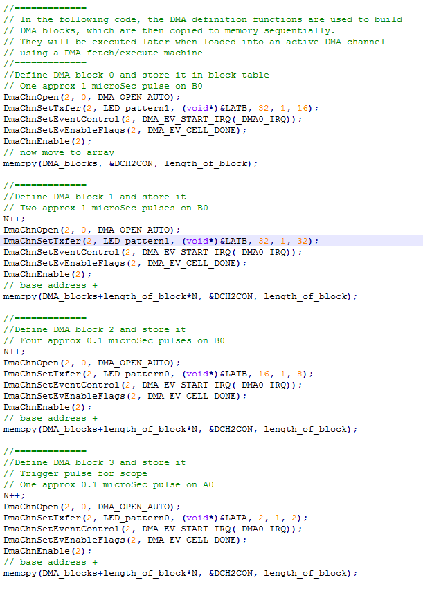
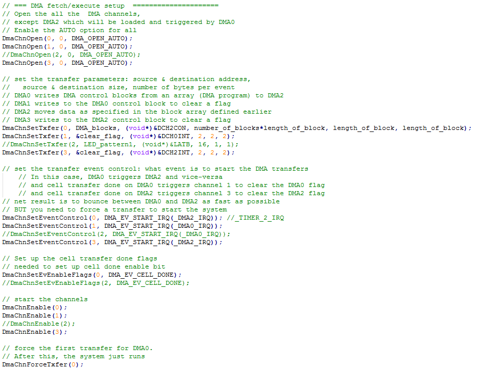
- Fetch/execute DMA weird machine: There is now a separate page for this topic, but a short summary is here. A table of DMA blocks is defined in memory, then uses DMA0 to cycle through the blocks by loading them into DMA2. DMA2 carrries out the data-move operation specified in the loaded block. In this example, the system just cycles through 4 blocks outputing pulse trains on portA and portB. Top trace is PortA0, bottom trace is PortB0.
- Using self-modifying block definitions, you can make DMA blocks that chain together to increment a variable and perform a conditional branch using the value of the variable.
Increment
- The increment scheme needs a lookup table in which each entry is the index value plus one (modulo 255 or less).
example of a module 3 table:
unsigned char inc_array[] __attribute__ ((aligned(256))) = {1, 2, 0};
The table
must be aligned in memory so that the lowest byte of the address is zero.
- DMA block N copies the 1-byte variable-to-be-incremented into the low byte of the source address field of block N+1,
- DMA block N+1 copies the modified source address contents back to the variable-to-be-incremented.
Conditional Execution
- The branch scheme needs a lookup table in which each entry is the 4*(index value).
example of a modulo 3 multiply table:
unsigned char offset_array[] __attribute__ ((aligned(256))) = {4, 8, 0} ;
The multiply table will be used to generate an 4-byte offset for each possible increment value.
The table
must be aligned in memory so that the lowest byte of the address is zero.
- The branch scheme also needs a lookup table in which entry is the actual memory address of a target block.
The target block will be moved into the execution path.
example of
jump table: unsigned int jmp_array[3] __attribute__ ((aligned(256))) ;
later in the code, set
jmp_array[0] = DMA_jump_blocks ;
jmp_array[1] = DMA_jump_blocks + length_of_block ;
jmp_array[2] = DMA_jump_blocks + length_of_block*2 ;
But NOTE that these are virtual addresses which need to be converted to physical addresses.
The conversion is done by only using the lower two bytes of the array value.
- The branch scheme also needs a lookup table of DMA control blocks (192 bytes)
#define number_of_jump_blocks 3
unsigned char DMA_jump_blocks[number_of_jump_blocks * length_of_block];
- DMA block N copies the 1-byte increment variable into the low byte of the source address field of block N+1,
which contains the base address of the offset array.
- DMA block N+1 copies the modified offset array address contents into the low byte of the source address field of block N+2,
which contains the base address of the jump array.
- DMA block N+2 copies the modified jump array address contents into the low 2 bytes of the source address field of block N+3,
- DMA block N+3 copies the DMA_jump_blocks source (192 bytes defining a DMA control blcok)
into the execution path at location N+4.
Code.
The following image shows the portA trigger pulses on trace 1, and the three different block outputs resulting from sequentially selecting one block to execute.
- The previous code was streamlined by introduction of macros for block definitions and macros for hard-to-read DMA source addresses. The resulting code looks a little like a privitive assembly language. Most of the block definition is repetitive. The only items which change much are the source address, destination address, source size, destination size, and cell-transfer size (all in bytes). Several blocks modify the source address of the next block to be defined, so a macro was written to abstract away the ugly syntax. The code to increment a byte variable is now:
make_DMA2_block(&inc_value, next_blk_src_addr, 1, 1, 1);
make_DMA2_block(inc_array, &inc_value, 1, 1, 1);
The first line reads the variable to be incremented into the low-byte of the inc_array address in the next block. Because the inc_array is byte-aligned, the low order byte
indexes this element corresponding to the value of inc_value variable. The array contents (index+1) is copied back to the variable in the second line.
Code.
- The next step is to allow arbitrary execution sequences to be spawned from the original sequence. The main change from example 7 is that the last step in computing the branch loads a new DMA0 block into the DMA0 channel control, rather than appending a DMA2 block to the execution list. The new DMA0 block effectively transfers control to a completely separate list of DMA2 blocks. The last block of that separate DMA2 list must reload the original DMA0 block to transfer control back to the original execution sequence. In the example code a 3-way branch is computed, so there must be three separate DMA0 blocks defined, each of which defines execution on one of three seperate DMA2 block sequences.
Using the CRC LFSR module to generate noise:
The DMA system can insert a hardware linear-feedback shift register (LFSR) into any one DMA channel.
The usual use would be to weakly encrypt data or produce a cyclic-redundancy checksum (CRC), but it can
also be used to generate a sequence of 16-bit pseudorandom numbers, perhaps to use as a sound effect.
The SFM can reorder bytes, and/or run a LFSR on the PIC32MX2xx.
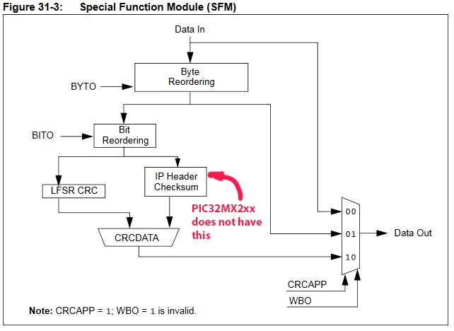
The LFSR CRC generator part of the SFM
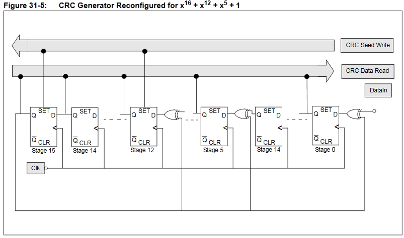
To set up the LFSR you need to configure a DMA channel, then add these statements.
// set up the LFSR
// void mCrcConfigure(int polynomial, int pLen, int seed);
// Arguments:
// polynomial; The generator polynomial used for the CRC calculation.
// pLen; the length of the CRC generator polynomial.
// seed; the initial seed of the CRC generator.
// max lengtth 16,15,13,4,1 0xa010 --- 0x1120 also sounds good
DmaCrcConfigure(0xa010, 16, 0xffff);
// send the data thru
#define appendMode 1
CrcAttachChannel(dmaChn, appendMode);
DmaCrcEnable(1);
The DMA transfer should be set up to feed a constant into the channel at a rate chosen by a timer event.
The output will clearly need to go to a DAC of some sort.
OLDER (obsolete) DMA Examples (Also see Instrumentation using DMA by Syed Tahmid Mahbub and Bruce Land)
- Waveform generator using DMA and 7-bit DAC
Generating a good sine wave requires a high sample rate, and reasonable accuracy DAC. A DMA channel is used to blast a sine wave (or any other periodic function) out of port B.0 to B.5 and B.7. (Note that B.4 and B.5 have a required config statement to turn off JTAG and clock input and that B.6 does not exist on this package). On a PIC32 running at 60 MHz, the DMA channel can support about 3.5 million bytes/sec in single byte transfer mode triggered by a timer (but with no ISR). The useful frequency range is 10 Hz to 200 KHz. During synthesis, NO cpu cycles are used.
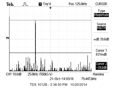
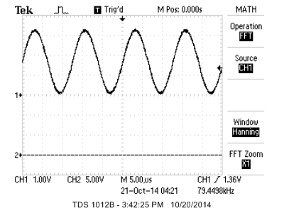
The sine table is dynamically sized according to the frequency range to minimize distortion. The sine wave delivered has the highest amplitude error harmonic about 40 db below the fundamental up to 100 KHz and less than 35 db above that frequency. Code is here. Spectrum and waveform of a nominal 80 KHz signal is below.
- Protothreads on PIC32 with DMA UART
Protothreads is a very light-weight, stackless, threading library written entirely as C macros by Adam Dunkels. As such, it is trivial to move to PIC32.
Adam Dunkels' documentation is very good
and easy to understand.
There is support for a thread to wait for an event, spawn a thread, and use semaphores. The Protothreads system is a cooperative multithread system. As such, there is no thread preemption. All thread switching is at explicit wait or yield
statement. There is no scheduler. You can write your own, or just use a simple round-robin scheme, calling each thread in succession in main.
Because there is no preemption, handling shared variables is easier because you always know exactly when a thread switch will occur. Because there is no separate stack for each thread, the memory footprint is quite small, but using automatic (stack) local variables must be avoided. You can use static local variables. Protothreads uses a switch-statement type construct to handle thread switching, so it is not possible to embed a thread-wait statement in a switch stanza.
You must read sections 1.3-1.6 of the reference manual to see all of the implementation details.
I hacked some of Dunkels' examples shown below and added:
- A millisecond resolution time thread yield macro
- Nonblocking UART receive thread
- Nonblocking DMA UART transmit thread
- A UART terminal command interpreter
- A simple rate scheduler that allows some threads more cpu time than others
- A 1-pin event debugger using the settable voltage reference pin.
Current Version:
To run protothreads you need to download pt_cornell.h. The Example1 test code also requires a UART connection to a terminal, as explained in a project further down the page. The test code toggles three i/o pins and supports a small user interface through the UART.It also emits three different amplitude debugging pulses on pin 25. By default this version of protothreads starts 32-bit timer45 and uses a timer ISR to count milliseconds. The following table has the protothread macro extensions and functions I wrote for the PIC32 and which are included in the header file..
Protothreads function |
Description
|
PT_YIELD_TIME_msec(delay_time) |
Causes the current thread to yield (stop executing) for the delay_time in milliseconds. The time is derived from a 1 mSec ISR running from timer5. |
PT_GET_TIME() |
Returns the current millisecond count since boot time. Overflows in about 5 weeks. The time is derived from a 1 mSec ISR running from timer5. |
PT_RATE_INIT() |
Sets up variables for the optional rate scheduler |
PT_RATE_LOOP() |
House keeping for the optional rate scheduler |
PT_RATE_SCHEDULE(f,rate) |
For thread f, set the rate=0 to execute always, rate=1 to execute every other traversal for PT_RATE_LOOP, rate=2 to every fourth traversal, rate=3 to every 8th, and rate=4 to every 16th. |
PT_DEBUG_VALUE(level, duration) |
Causes a voltage level from 0 to 15 (1 implies ~150 mV) to appear at pin 25 (CVrefOut) for duration microseconds (approximately). Zero duration means hold the voltage until changed by another call. |
int PT_GetSerialBuffer(struct pt *pt) |
A thread which is spawned to get nonblocking string input from UART2. String is returned in
char PT_term_buffer[max_chars]. If more than one thread can spawn this thread, then there must be semaphore protection. Control returns to the scheduler after every character is received. The thread dies when it recieves an <enter> |
int PutSerialBuffer(struct pt *pt) |
A thread which is spawned to send a string input from UART2. String to be sent is in
char PT_send_buffer[max_chars]. If more than one thread can spawn this thread, then there must be semaphore protection. Control returns to the scheduler after every character is loaded to be sent. The thread dies after it sends the entire string. |
int PT_DMA_PutSerialBuffer(struct pt *pt) |
A thread which is spawned to send a string input from UART2. String to be sent is in
char PT_send_buffer[max_chars]. If more than one thread can spawn this thread, then there must be semaphore protection. Control returns to the scheduler immediately. The thread dies after it sends the entire string. |
void PT_setup (void) |
Configures system frequency, UART2, a DMA channel 1 for the UART2 send, timer5, and the debug pin Vref controller. |
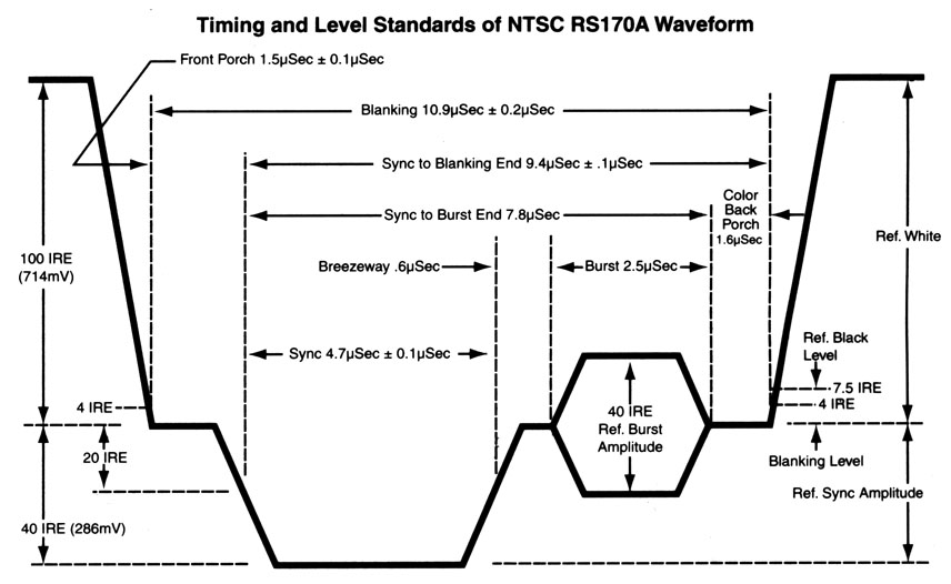
- NTSC video synthesis and output using DMA
--NTSC video is an old standard, but is still used in North America
for closed circuit TV. It is fairly simple to generate a black/white NTSC signal. Also, the frame buffer for a 1-bit, 256x200 pixel image is only 1600 words (6400 bytes) of RAM.
Chapter 13 of Programming 32-bit Microcontrollers in C: Exploring the PIC32 by Lucio Di Jasio was very useful. I used Di Jasio's method of generating sync pulses using one output-compare unit. Video is sent to the SPI controller using DMA bursts from memory (also similar to Di Jasio), but DMA timing-start control was implemented using another output-compare unit rather than chaining two DMA channels. This allowed easy control of video content timing.
Timer2 is ticking away with an match time equal to one video line time. Ouput-compare 2 is slaved to timer2 to generate a series of pulses at the line-rate. The duration of the OC2 pulses (for vertical sync) is controlled by the Timer2 match ISR in which a simple state machine is running, but the pulse durations are not dependent on ISR execution time. Output-compare 3 is also slaved to timer2 and set up to generate an interrupt at a time appropriate for the end of the NTSC back porch,
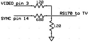
at which time the DMA burst to the SPI port starts. I got best video stability when the core is running at 60 MHz and the peripheral bus running at 30 MHz. The first example is just a bounding ball with some text. The example requires that the ascii character header file be in the project folder. The DAC which combines the SYNC and video signal and adjusts to levels to standard video is:
--The second example is a particle system explosion.
Without doing any space optimization 1500 particles (along with screen buffer) use up memory. All the positions can be updated in every frame. Giving each particle a high initial velocity, and high drag makes a nice cloud.
-- The third example is a particle system fountain, which is a slight modification of the explosion. I optimized the point-draw and one ISR for more efficient execution. Frame update now takes 7.2 mSec. Video.
The overhead for NTSC TV signal generation is about 5 microSec per 63.5 microSec line, or about 8%. You should use this optimized version for an intensive animation.
A small variation makes the particle system fire to the side. Video.
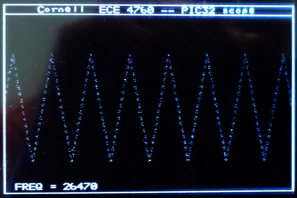
--The fourth example turns on the ADC to make an oscilloscope. The ADC is set up to trigger from the timer3 compare match signal, but without turning on an ISR. A DMA channel transfer is then triggered by the ADC done signal to dump the ADC results to memory at up to 900 Ksamples/sec. This ADC hardware process runs at the same time as the video update hardware process, so video is not disturbed.
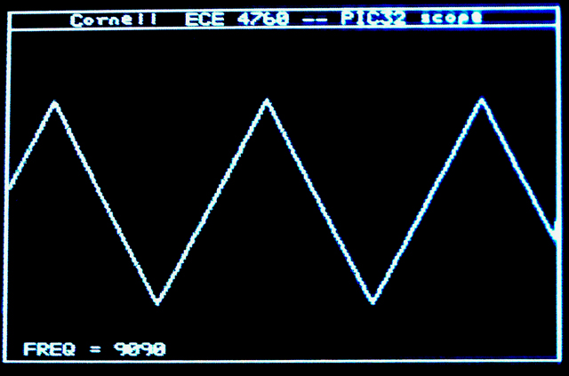
CPU load is small so there is time to draw the ADC waveform to the screen. It would be straightforward to add a button state machine for scope control and a FFT. The following image is captured from the NTSC screen and shows the scope running at 900 Ksamples/sec and displaying a frequency estimate. Video is running at 500 Ksamples/sec ADC rate.
-- The fifth example is a vector variation of the scope. Drawing all the vectors slows the redraw down so that the scope is updated 30 times/sec.
Video is running at 900 Ksamples/sec. Still image below.
- Using the CRC LFSR module to generate noise.
The DMA system can insert a hardware linear-feedback shift register (LFSR) into any one DMA channel.
The usual use would be to weakly encrypt data or produce a cyclic-redundancy checksum (CRC), but it can
also be used to generate a sequence of 16-bit pseudorandom numbers, perhaps to use as a sound effect.
The SFM can reorder bytes, and/or run a LFSR on the PIC32MX2xx.
The LFSR CRC generator part of the SFM
To set up the LFSR you need to configure a DMA channel, then add these statements.
// set up the LFSR
// void mCrcConfigure(int polynomial, int pLen, int seed);
// Arguments:
// polynomial; The generator polynomial used for the CRC calculation.
// pLen; the length of the CRC generator polynomial.
// seed; the initial seed of the CRC generator.
// max lengtth 16,15,13,4,1 0xa010 --- 0x1120 also sounds good
DmaCrcConfigure(0xa010, 16, 0xffff);
// send the data thru
#define appendMode 1
CrcAttachChannel(dmaChn, appendMode);
DmaCrcEnable(1);
The DMA transfer should be set up to feed a constant into the channel at a rate chosen by a timer event.
The output will clearly need to go to a DAC of some sort.
- DMA performance.
PIC32 supports direct memory access from/to peripherials, flash memory and RAM.
Code is based on examples from
C:\Program Files (x86)\Microchip\xc32\v1.31\examples\plib_examples\dma
--
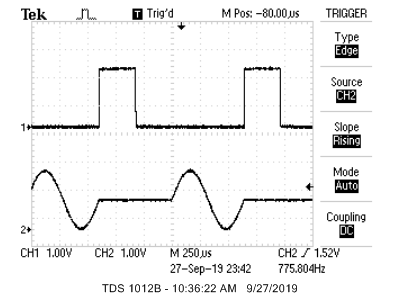
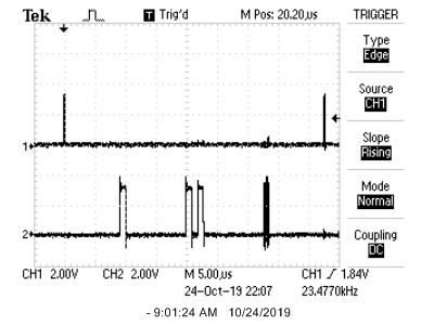
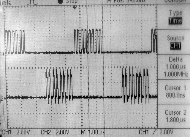
The first image below shows a DMA burst on the top trace and a separate port pin being toggled in main on the bottom trace. The DMA burst is triggered by a timer interrupt, but the interrupt does not trigger an ISR, just the DMA. Individual transfers within the burst are not uniform in time and range from 10 MHz to 5.5 MHz. The code sets up the DMA to burst 16 entries from a table (in flash or RAM) to an i/o port once every 2.5 microseconds. If the burst length is set to one (one byte at a time) triggered by a timer, the fastest I could get the system to go is 3.7 MHz (270 nSec per transfer).
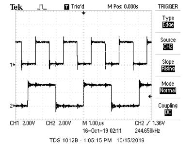
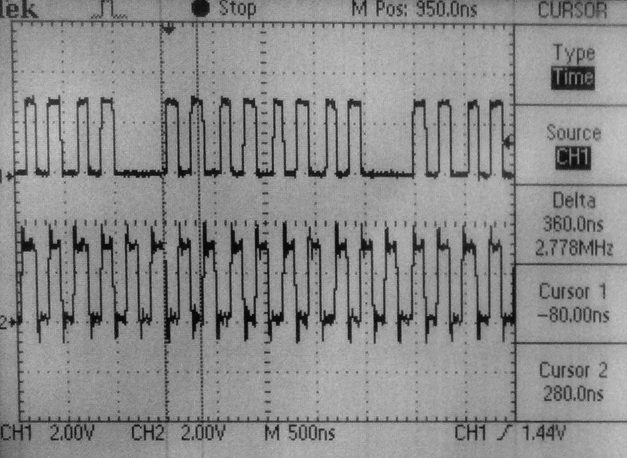
-- The second image shows two DMA channels (code) activated by the same timer IRQ every 5 microSec. Both DMA channels have the same DMA priority and both are sending 16 bytes to an i/o port. The DMA controller seems to interleave 4-byte bursts from each DMA channel. Each byte within each 4-byte burst takes 100 nSec. The latency between one channel and the other is about 72-120 nSec (~3-4 cycles).
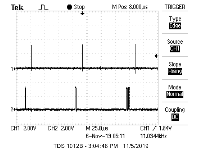
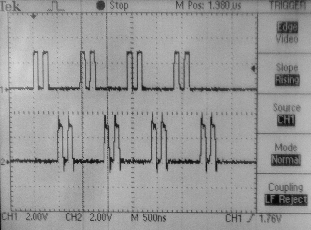
-- The third image shows
two DMA channels (code) activated by the same timer IRQ every 5 microSec. The DMA channels have the different DMA priorities and both are sending 16 bytes to an i/o port. The high priority channel sends, then the low priority channel. There is a 4 or 5 cycle latency between the bursts.
References:
- Beginner's Guide to Programming the PIC32 Paperback by Thomas Kibalo
and more info
- Programming 32-bit Microcontrollers in C: Exploring the PIC32 by Lucio Di Jasio
and more info
- PIC32 Architecture and Programming by Johm Loomis Numb3rs
- Intro to PIC32 architectture
- PIC32 tutorials
- UMass M5 PIC32 tutorials and specifically for the PIC32MX220
- Northwestern University mechatronics design wiki:
- code examples,
- benchmarking,
- Embedded programming on PIC32
- Tahmid's Blog
- chipKit
- Arduino library for PIC32
- Microstick configuration
- project zip
- DSP experiments and more and
- RTOS
- http://www.freertos.org/ and Microchip PIC32 FreeRTOS Reference Designs and MPLABX and ECE443 ref
- TNKernel
- ERIKA Enterprise
- Q-Kernel
- Protothreads by Adam Dunkels
- Protothreads -- similar to Dunkels, but different implementation only for GCC
- MIPS32 docs
- Architecture
- instruction set
- privliged resources
- Microchip Docs
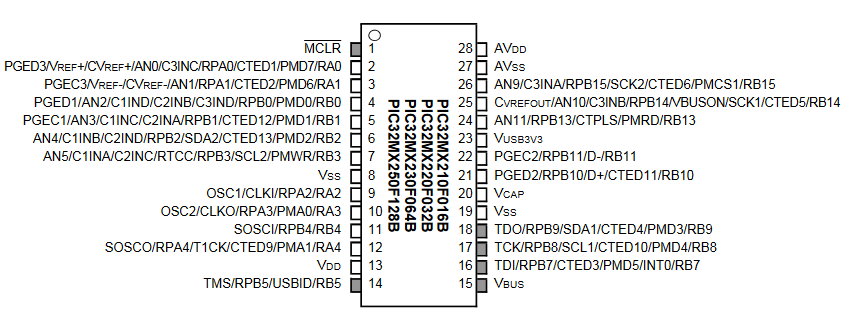
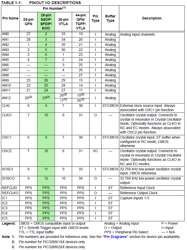
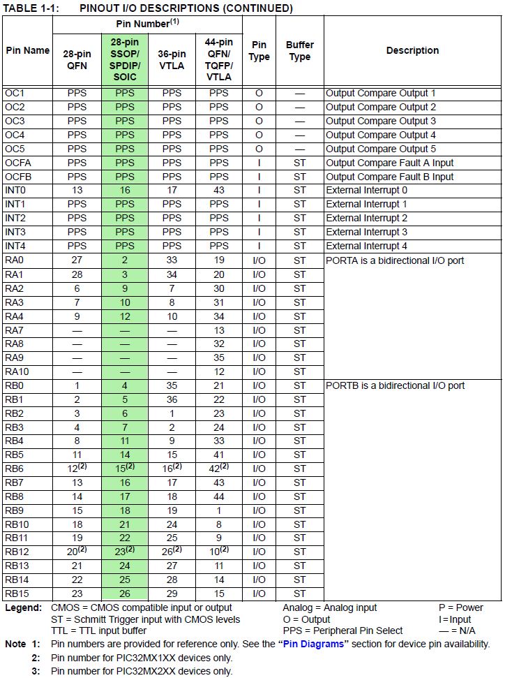
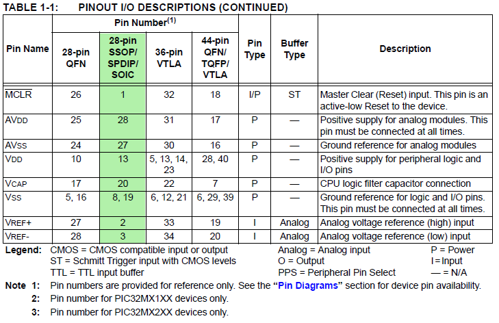
- PIC32MX250F128B PDIP pinout by pin
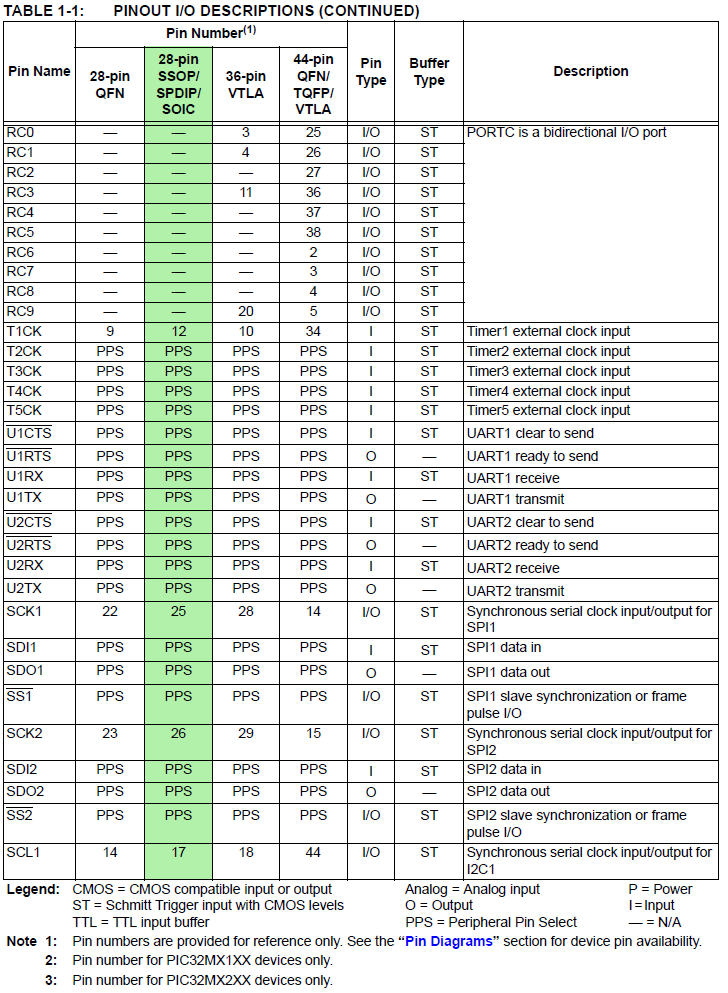
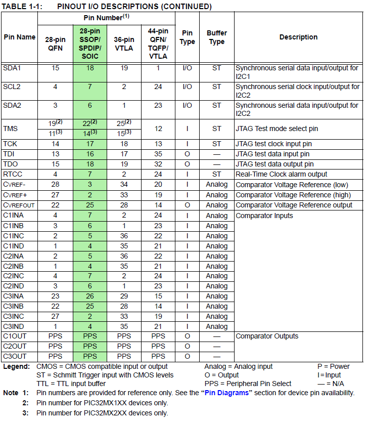
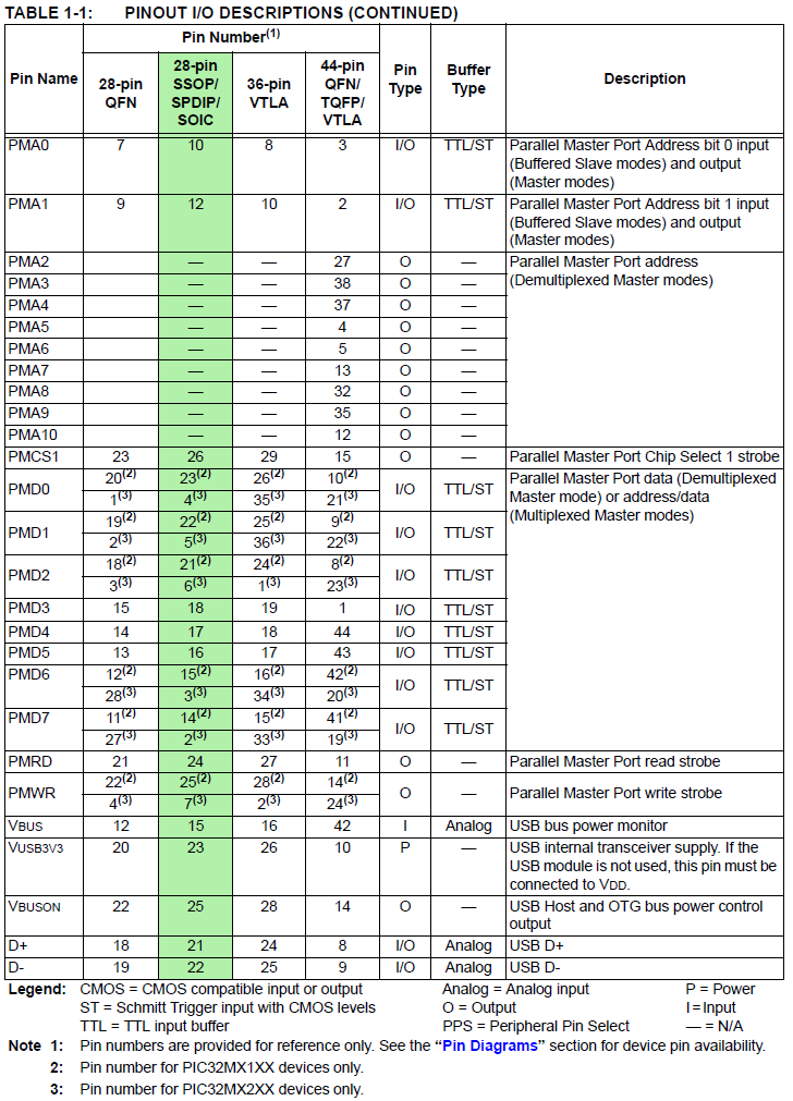
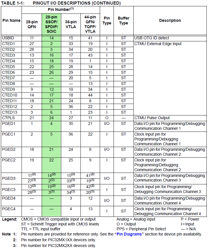
- PIC32MX250F128B ::: Signal Names=>Pins ::: 1, 2, 3, 4, 5, 6, 7 PDIP highlighted in green (for PPS see next tables)
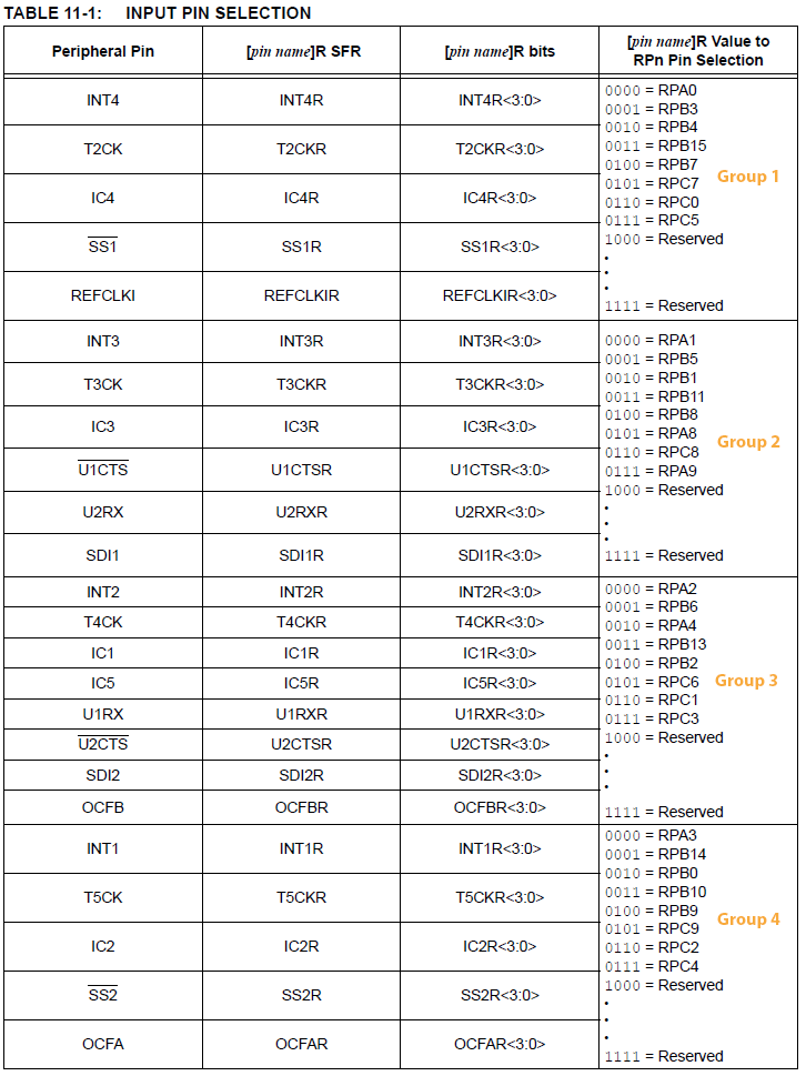
- PIC32MX250F128B Peripheral Pin Select (PPS) input table
example: UART receive pin ::: specify PPS group, signal, logical pin name
PPSInput(2, U2RX, RPB11); //Assign U2RX to pin RPB11 -- Physical pin 22 on 28 PDIP
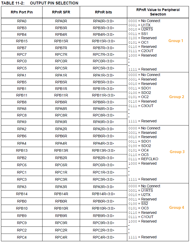
- PIC32MX250F128B Peripheral Pin Select (PPS) output table
example: UART transmit pin ::: specify PPS group, logical pin name, signal
PPSOutput(4, RPB10, U2TX); //Assign U2TX to pin RPB10 -- Physical pin 21 on 28 PDIP
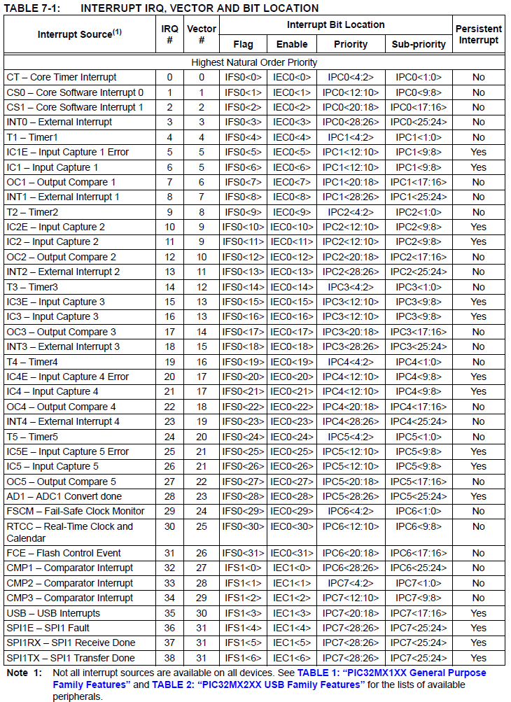
- PIC32MX1XX/2XX Interrupt Table 1, 2 and int_1xx_2xx.h -- interrupt IRQ names and vector names
- plib.h names of peripherial header files
-----------------------------------------------------------------
- Getting started with PIC32
- MPLABX IDE users guide
- PICkit3 Users Guide and poster
- 32_bit peripherials library
- 32 bit language tools and libraries including C libraries, DSP, and debugging tools
- XC32 Compiler Users Guide
- microstickII pinout
- PIC32 reference manual
and more from Northwestern University mechatronics design wiki, PIC32 page
- MIPS-M4K Core
- 2xx_datasheet
- Microchip doc site on this page choose
Documentation from the left column.
The Reference Manual is particuarly useful
- USB Embedded Host Stack
- chipKIT (PIC32 arduino library)
- code examples (choose PIC32 in product family dropdown)
- code libraries (choose PIC32 in product family dropdown)
- application notes (choose PIC32 in panel)
- Harmony for PIC32 -- docs --
- Microchip TCP/IP Stack Application Note
- External Refs back to this work
- http://dangerousprototypes.com/2014/07/15/pic32-oscilloscope/
- http://hackedgadgets.com/2014/07/14/pic32-oscilloscope/
Copyright Cornell University
February 26, 2020