


High Level Design
Rationale and Sources of Idea
There are many motion tracking devices in the market today that allow humans to interact with objects in the virtual world such as the Kinect sensor and Wii remote. These systems use a variety of infrared, distance, acceleration and orientation sensors to many body motions. The goal of this project is to create a reliable 2D motion detection system that only uses a camera to detect and track humans. The motivation behind this project is to avoid using too many sensors for motion detection or any additional identifiers for body parts other than the user's own skin. I got this idea from the Face Tracking+Perspective Projection project and the Real-Time Face Detection and Tracking project. Both of these projects had demonstrated that reliable skin detection for humans is possible.
Background Math
Skin Filter
According to Hardware Implementation for Face Detection on Xilinx Virtex-II FPGA Using the Reversible Component Transformation Color Space and this paper, a human skin pixel is only dictated by its R and G values. In the Face Tracking+Perspective Projection project, logrithmetic values of R and G are used compute if a pixel can be skin. The drawback in this case is that the ranges of logrithmetic R and G values need to be tuned for each skin color. On the other hand, the Real-Time Face Detection and Tracking project uses YUV color or the difference between R, G and B values to compute skin pixels. The advantages of this method are that all of the skin color detection operations are combinational and the intensity of the pixel is removed (component Y). Since the intensity is what dictates the shade of the skin, removing the intensity component allows all skin colors to be detected given a single detection algorithm. Specifically, RGB values can be transformed into YUV components via the following equations:
To detect skin in YUV color space, the following relationship must be satisfied for 10bit RGB color:
10<U<74
The paper that generated the range values above only performed analysis on humans in pictures for 8bit color. Since the color used in the VGA controller for DE2 board is 10bit RGB, the above values are modified to allow more precision.
100<U<500
The paper also suggested placing a simple color filter to rule out non-skin pixels by ensuring R>G and R> B. Since the U value must be positive to fall within the valid skin color range, only the R>B check is performed in the filter.
3D Projection
In this project, I made the assumption that the user is always looking into the camera regardless of what position the user is in. This allowed me simplify the calculation for 3D projection significantly. In the case of the head, I simply drew 2 squares, one smaller than the other and placed inside the bigger square when the user is in the center of the screen. The 4 corners of each square are connected to construct a 3D cube. To simulate projection based on the user's view, I compute the centroid of the smaller cube based on the current values of the head centroid, 7 most significant bits of the centroid's coordinates and an offset that cancels the 7 most significant bits' contribution when the head centroid is in the center of the screen. For example, given a 640x480 VGA screen and a projected small square size of 60x60 pixels, the following formula is used to compute the location of the square's center:
Xsq=Xhead+(Xhead/8)-40
As the user moved across the screen, the small square would change locations based on the view of the user. When Xhead is in the center of the screen, Xsqsmall=320+320/8-40=320 and Xsqlarge=320. When Xhead is on the left side of the screen, Xsqsmall=64+64/8-40=32 and Xsqlarge=64. Similarly, when Xhead is on the left side of the screen, Xsqsmall=3576+576/8-40=608and Xsqlarge=576. This gave a 3D illusion to the simulation and allowed the simulated human model to be more realistic.
Logical Structure
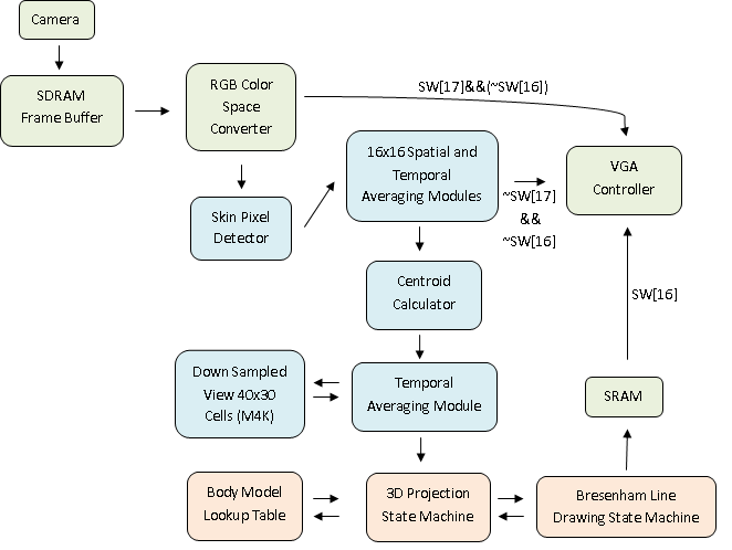
The RTL level diagram for the entire system is shown below. The Skin Pixel Detector computes whether a pixel can be a skin pixel for every pixel in the VGA feed. Then, spatial averaging is performed on the whole screen by down sampling from 640x480 to 40x30 to allow better noise rejection. The down sampled screen is averaged over time to improve pixel stability. The resulting down sampled skin map is very stable. There was no visible camera noise in the down sampled view. Then, the centroid for head, left and right arms are computed and averaged over time to generate smooth animation between 16x16 down sampled cells. Lastly, a 3D model of a human body is drawn in SRAM based on the location of the 3 centroids using a hardware Bresenham line drawing module. SW[17] and SW[16] allows user to switch current VGA view.
Hardware/Software Tradeoffs
Early on in the project, I have considered to use custom processors such as Nios or Pancake to run Bresenham line drawing algorithms or filter processing. However, since the frame buffer for the camera uses SDRAM for storage, the 3D projected box components are stored in SRAM for a 640x480 screen and the skin filter uses M4K blocks for down sampled skin pixel storage, there was no space left on the DE2 board to run Pancake or Nios. As a result, the entire project is written using Verilog. In this case, software component of the project needed to be abandoned due to limited resources on board.