"Explore the world of Mandelbrot Set with hand controlling"
Project Soundbyte
Introduction top
This is a hand-controller Mandelbrot Set which can realize real-time interaction with a player. The prototype we have made is able to move the pane for the Mandelbrot and to zoom in for more details as the player’s hand approaches the video camera or move the relative position. For each frame update on the VGA, the FPGA re-calculates the new color for each pixel on the Mandelbrot Set according to the player’s gestures.
Expect for acquiring images from video camera and displaying the Mandelbrot Set, the FPGA board is also responsible for detecting skin color, localizing hand’s centroid, estimating the distance, as well as calculating the Mandelbrot Set. In order to provide a smooth visual experience, we have applied some control methods and image processing techniques to reduce the disturbance. Those tricks that have proved to improve the performance includes down-sampling, averaging, low-pass filtering on the images as well as tricking the tolerance range and the change rate between frame updates.
High Level Design top
• Rationale and Inspiration
The inspiration for the project came from the increasing usage of gesture controlled real-time system. Impressed by the beauty of Julia Set we implement in Lab 4, we want to develop the Julia Set to a higher calculation speed which would be implemented in real-time displaying and updating. Therefore, we combined the two parts together and want to implement a real-time hand controlled Mandelbrot Set.
• Background Math
Mandelbrot Set :
Precisely, the Mandelbrot set is the set of values of c in the complex plane for which the orbit of 0 under iteration of the complex quadratic polynomial
 >
>
remains bounded.That is, a complex number c is part of the Mandelbrot set if, when starting with z0 = 0 and applying the iteration repeatedly, the absolute value of zn remains bounded however large n gets.
In our project, C was determined by the position on the VGA screen, X axis provided the real part for the complex number C, and Y axis provided the imaginary part for C. And the range for the first screen Mandelbrot Set was X : (-2,1) ; Y: (-1.5, 1.5).
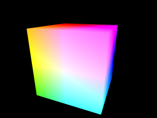
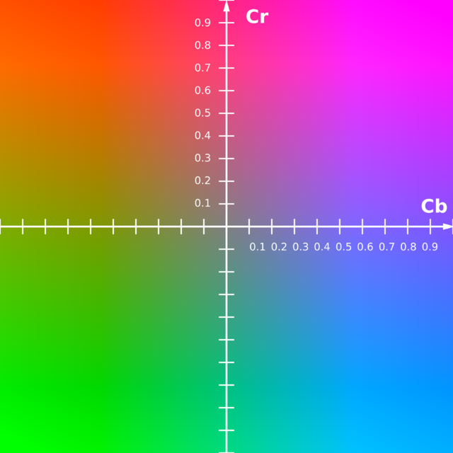
YUV Colorspace :
The Y component determines the brightness of the color (referred to as luminance or luma), while the U and V components determine the color itself (the chroma). Y ranges from 0 to 1 (or 0 to 255 in digital formats), while U and V range from -0.5 to 0.5 (or -128 to 127 in signed digital form, or 0 to 255 in unsigned form). Some standards further limit the ranges so the out-of-bounds values indicate special information like synchronization.
 |
 |
 |
YUV cube in dark side(Y=0) |
YUV cube in bright side(Y=1) |
YUV colorspace (Y=0.5) |
One neat aspect of YUV is that you can throw out the U and V components and get a grey-scale image. Since the human eye is more responsive to brightness than it is to color, many lossy image compression formats throw away half or more of the samples in the chroma channels to reduce the amount of data to deal with, without severely destroying the image quality.
There are many slightly different formulas to convert between YUV and RGB. The only major difference is a few decimal places. The CCIR 601 Standard (now ITU-R 601) specifies the correct coefficients. These formulas assume U and V are unsigned bytes.
R = Y + 1.4075 * (V - 128)
G = Y - 0.3455 * (U - 128) - (0.7169 * (V - 128))
B = Y + 1.7790 * (U - 128)
Y = R * .299000 + G * .587000 + B * .114000
U = R * -.168736 + G * -.331264 + B * .500000 + 128
V = R * .500000 + G * -.418688 + B * -.081312 + 128
• Logical Structure
The block diagram shown in figure illustrates the basic structure of our project. The block diagram below is a modified version of the DE2_115_TV design from the Altera DE2-115 User Manual. We used the Video Example from Altera as our base code. It simply decodes the signal from camera and outputs it to the VGA by using the ITU-R 656 Decoder, SDRAM buffer and modules to convert YCrCb to RGB and VGA controller.
We added a skin detection filter in the YCrCb module to filtered out all colors except the skin color. The low pass filter were used to get a smooth centroid point . The Mandelbrot Set module using multi-pipelines which updated VGA display in real time was controlled by the hand tracking module.
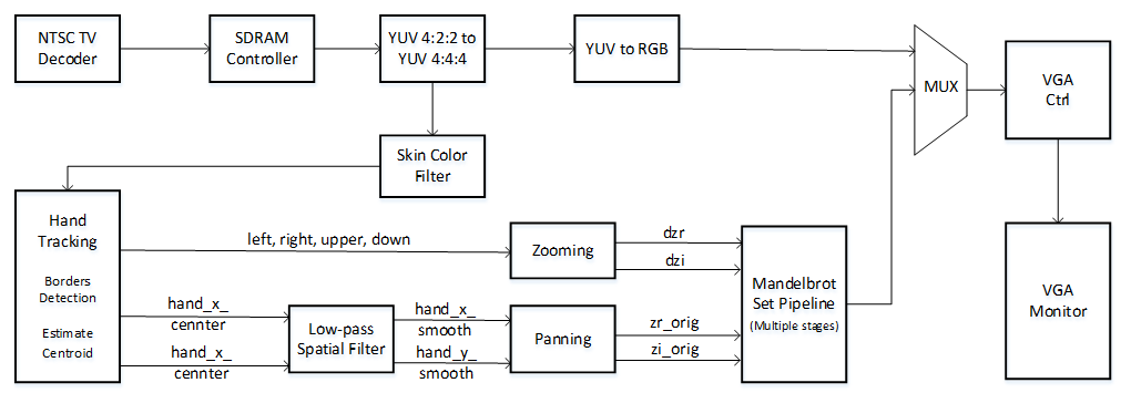
Figure 1. Block Diagram for High Level Design
• hardware/software tradeoffs
There is no software in this design, all functionality was implemented using custom Verilog hardware. In hardware, there were several tradeoffs between speed and accuracy and the resource available on DE2_115 board. When using multi pipeline for the Mandelbrot Set on VGA clock, more pipelines lead to more details on the edge of the Mandelbrot Set. However, to calculate one pixel through more iterations, more times must be used as well as the multipliers if three 27 bit multipliers were needed per iteration.
As for the low pass filter we implemented in the hand tracking, if α chosen was close to one , which means the filtered position more relay on the new position, the cursor is easily to follow the moving hand but also easily get interfered by slightly change of hand position, which made the cursor display very unstable. However, if choose the α too small, like less than 0.2, the cursor might be more stable but harder to move. So finally, we chose the α to be 0.25 experimentally, which got a pretty good filter result.
When deciding which Altera Board to use, we chose DE2_115. The reason is because it has more multipliers. The downside is that we got some overhead in getting the Altera example project up and running on the DE2-115 board, but definitely this cost was far outweighed by the benefits of increased computational power.
• Relationship of design to standards
Our design requires the video signal to be in NTSC video standard form. The data is output as a VGA signal. Thus, television and computer display standards are at play. These standards are implemented using DE2_115_TV example from Altera.
Program/Hardware Design top
Overview :
The implementation for this lab is entirely dependent on the hardware. Basically, our project could be divided into three parts. The skin color based hand tracking, multi-pipelined Mandelbrot Set and the interface between the hand-tracking part and the Mandelbrot displaying on VGA monitor. For the connection between the camera and FPGA, we learned from the Altera DE2_115_TV example to get familiar with the setups. As for the hand tracking part, suggested by Prof. Bruce Land, we decided to use YUV color space to detect the skin color. For the Mandelbrot Set, we used a completely different method from lab4, referred from Nerdy Stuff, we used 23 parallel pipelines without using any RAMs. The high level blocks combine with RTL block diagram below also helps explaining the connections between all functions and modules for this project design.
Video and Camera Setup :
We used standard VGA_Ctrl module provided by Altera. In this module , parameters are defined by host side, VGA side and control side. The host side take input from FPGA and output to VGA side. The VGA_X and VGA_Y defined a pixel regarding the X/Y axis position. The host side also has the mVGA_R, mVGA_G and mVGA_B RGB channels for color display. VGA_HS is horizontal sync which starts a new line and VGA_VS is vertical sync for a new frame.Several always @(posedge iCLK) blocks are used to correlate input wires with output registers. For example, the sync output is based on incrementing a counter in the always statement. Clock and reset are also implement for synchronization and control purpose. The VGA controller Verilog file can be referred on ECE5760 website.
The camera we use is HTC 231 which is available in the lab, generating standard NTSC TV signal. Schematic shows below is the setups on DE2 115 board.
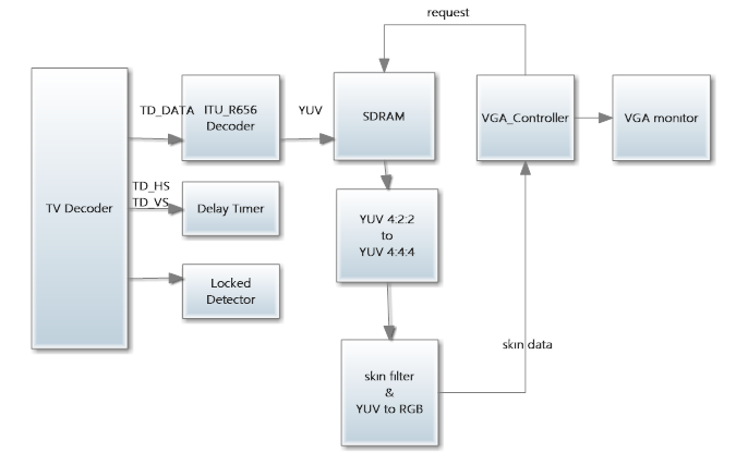
Figure.2 Block Diagram for camera setups on DE2 115 board
The VGA control clock used in this project is the TD_CLK27 27 MHz standard video clock. After the NTSC signal decoded by ITU_R656, the color format is 4:2:2 YUV format and stored in SDRAM. As VGA buffer, SDRAM would be requested by VGA_Ctrl. Since the VGA_Ctrl host side color was in RGB format, the 4:2:2 YUV format needed to be convert to RGB and truncated to 8 bit VGA_R, VGA_G and VGA_B. The mirror effect also added for more explicit user control.
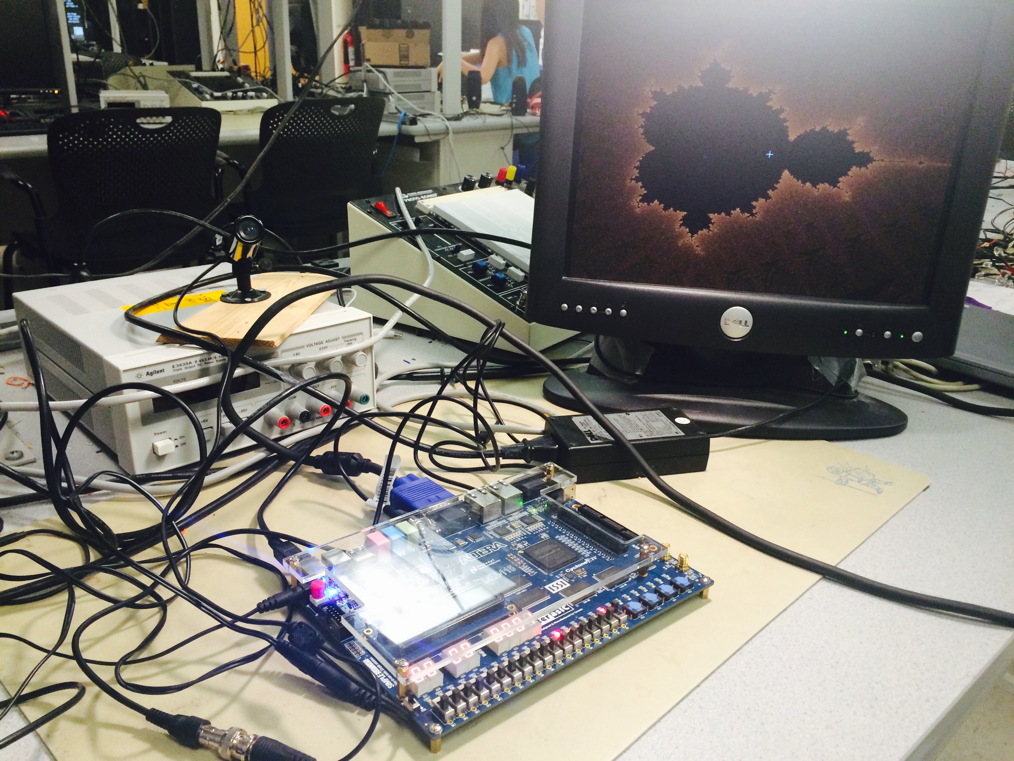
Figure.3 Hardware Setups
Skin Color Detection :
For the skin color detection, we use YUV color space other than RGB to determine the skin color range, which could eliminate the effect of intensity (white or dark) of skin color. Since the NTSC signal decoded by 656 decoder into YUV format, we could determine the skin color directly on the YUV channel before it convert to RGB for VGA controller.
We also referred some papers for human skin color, and choose the following range as skin color:
(8 bit)80 <= U <= 120 ;131 <= V <=185
A FSM (Finite State Machine) was used to implement the checking for hand position every frame. And the centroid calculation for the hand position was implemented by finding the four edges (upper, down, left and right )of the “skin chunk “ that detected. In order to make sure that the cursor which we used to track the hand position would not be interfered by other skin colored objects, the cursor would first be trained at the very initial frame. The way to implement that is to put the cursor at the center of the screen when reset, and followed the “skin chunk” that entered this area. In this way that we could eliminate the interference that caused by face or other skin colored objects in the environment.
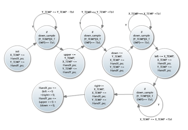
Figure.4 FSM for Hand tracking
Cursor Stabilization (Downsampling and Low Pass filter) :
In order to make the calculated position stable, we down sampled the VGA signal by sixteen (the new resolution was 40 by 30) and set the threshold as 4%, which means when over 10 of the 256 pixels are detected as skin then set the “big” pixel as skin pixel. We tend to eliminate the “black holes” inside the skin color chunk in this way, and result showed it worked perfectly. The fall 2009 ECE 5760 project: Real_time Face Tracking - Perspective Project on FPGA by Chuck Yang and Jasper Schneider Provides the knowledge fundamental for such a down_sampling based detection scheme.
Instead of using SRAM or M9K to store the down sampled values, we used LEs (a 40 by 30 register array)to make the reading and writing procedure more simple. But the trade off was a longer compiling time.
In addition, Despite of the down-sampling applied, the centroid of the hand would still be hopping among neighboring pixels once the hand have a slight displacement. We further stable the movement of centroid by applying a low-pass filter on both x and y velocity.

By rearranging the expression, we get
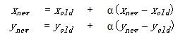
the multiplication in which can be easily implemented using panning.
The α we used in this project was 0.25, which was an experimental value that balanced the tracking sensitivity and displaying stabilization. Since for smaller α, which indicated the old_input dominate the output, the cursor would be more stabilized but “harder” to move.A mean filter was also be tied in the project , but the result was not as good as the low pass filter.
Mandelbrot Set - Parallelization Scheme :
In this project, we used a completely different method to implement the Mandelbrot Set comparing to Lab4. Instead of using SRAM to store the iteration value n, which was related to color, no writing or reading from SRAM or M9K was applied in this project.
Referring Nerdy Stuff’s multi-pipelined Mandelbrot Set,we use a real-time calculation and displaying of each pixel on VGA screen. For every complex number on the screen (every pixel) 23 pipelines needed to be go through to calculate the iterations before convergence. Which means the result displayed on the VGA screen were actually the pixel calculated 23 VGA clocks before, which was the pixel 23 ahead in x direction. This won’t affect the display result so significantly as long as the pipelines we used were limited. And also, for each pipeline doing one - time iteration, using three multipliers, the number of pipeline also limited by the multipliers that available on DE2_115 board.
The advantage for this method is that we could make sure the time for one whole screen calculation was one VGA frame time exactly, no matter what the zoom level. To make sure of this, the time for one pixel calculation could never longer than 40 ns, which is the VGA scanning time for one pixel (under 640 by 480 resolution). This also set the limit for the number of pipelines.
The diagram below explaining the Mandelbrot set parallelization scheme.
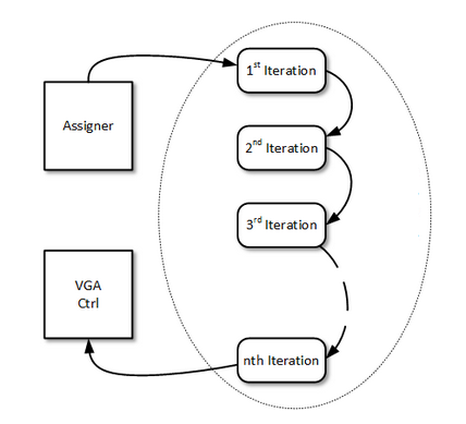
Figure.5 Dataflow for Multi-pipelined Mandelbrot Set
Interface Controlling Mandelbrot Set :
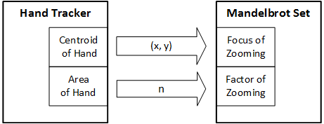
Figure.6 Block Diagram for Interface
For the panning control, first thing need to figure out was the direction of the moving hand. For instance, when hand moves toward right, mean more patterns would be seen on the left side, then the new image should be updated with initial position shift a little bit to left. In our project, four directions, right, left, upper and down are implemented, and the speed for panning was 8 pixel per frame.
The zooming effect is realized by adjusting the resolution of real and imaginary step for each pixel on the Mandelbrot Set. In order to present a zoom-in effect, the difference between each pixel should become smaller as one’s hand approaches closer to the video camera; and vise versa. We introduced a zooming factor to quantitatively describe the resolution which determines both real and imaginary step for pixels in the Mandelbrot Set in roughly a linear relation. This conversion is done by the Converter 2 in the zooming module (see Figure ).
According to the relative distance between and and the camera, which is roughly estimated by calculating the area of the hand. This can be easily acquired by multiplying the width and height of the rectangle that fits right out of the hand. The zooming factor will have a linear relation to the percentage of pixels in the camera field covered by the hand. This conversion is done by the Converter 1 in the zooming module (see Figure ).
Controller : In order to have a smooth effect, there should not be any abrupt change in the increment or decrement on the zooming fraction. We adopted the most simple way by setting a constant value for both the increment and decrement, which proved to have a very responsive and smooth effect for zooming. Whenever the error between the expected zooming fraction is larger than a tolerance range, the actual zooming fraction will be adjusted until it reaches the expected value. This controller forms a negative feedback loop in the zooming module, which is illustrated in the control block diagram (see Figure ).
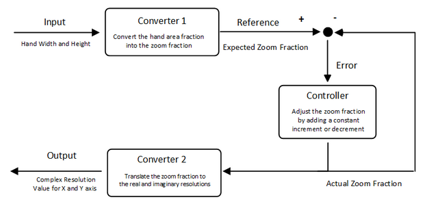
Figure.7 Zoom Diagram Block
Displaying the Final Product :
On the top module three switches control what is displayed on the VGA screen. The first mode is to display the down sampled skin color image, with detected skin color displayed in white blocks while black for the rest of the area. This mode could help us first check the lighting conditions for the hand tracking. We want to make sure the skin color could be correctly detected before moving to the next steps.
The second mode is the camera image with a cursor following the moving hand. Cause the cursor needed to be trained at reset, this image could help to make sure the hand position was correctly calculated.
The third mode the Mandelbrot Set image with hand position controlled. Cause we doing the zoom in and out with panning at the same time. So sometimes the image would suddenly zoom out because the user’s hand might move out of the camera. To make the display more explicit, we added an additional switch to display the panning only.
Code Reference :
For Hand tracking part, We referred “ Hand Tracking Pong” former ECE 5760 final project by Hanting Lu and Kedari Elety and Realtime Face Tracking - Perspective Projection on FPGA by Chuck Yang and Jasper Schneider. The link to their project can be found here. Also, “Fruit Ninja with video tracking” by Yuan Cui, Jin Sha and Wei Wang was referred for the centroid calculation method.Code could be found here.
For Mandelbrot Set, We referred Nerdy Stuff ’s blog for the multi-pipeline scheme.
Other Attempts :
There is an alternative way which promises to ensure real-time update while keeping enough fixed-point precision for differentiating the details in Mandelbrot Set. As is demonstrated in Figure , this approach fully makes use of the memory available on the board. While the clock rate for VGA displaying module is limited to 25 MHz, we could run the SRAM module and the computation module at fourth this speed. We have rewritten the module for each pipeline so that it does the calculation for each iteration within only one cycle. Each pipeline only accepts an zr and zi coordinate of a point on the Mandelbrot Set and outputs the result back to the upper module.
We have successfully drawn a full Mandelbrot Set using producer-consumer scheme with a single pipeline. The speed is within 0.1 seconds which as fast as what we achieved using 8 pipelines in the previous approach. After we implemented the multi-pipeline scheduler, we could expect to achieve 10 frames per second when the Mandelbrot Set has been zoomed in by a factor of 2, which promises to give a quite smooth visual effect in real-time.
Results top
• Speed of Execution:
Our system operates in real time to display the Mandelbrot Set controlled by a moving hand. Every time the whole image was recalculated and the whole screen could finish calculation in one frame time so the speed was pretty fast and no black screen would be seen when new images updated.
• Accuracy: :
For hand tracking, in most cases the cursor could follow the hand closely, but under relatively high speed of a moving hand, the cursor might lost tracking. This situation could be modified by increasing the α sightly, but it might also affect the stability of the cursor.
Since the way we did the centroid calculation was to find the four edges of the skin-colored chunk, users are recommended to wear long shirts or wear a watch to control the Mandelbrot Set.
The details of the Mandelbrot Set were not perfect, since we only implement one iteration per pipeline, which means considering the limited multiplier resource on DE2- 115 board and the timing issues, the iterations for each pixel was limited. This caused the details of the Mandelbrot Set was hard to be seen. For the same reason, the Mandelbrot Set could not be deeply zoomed in either. The limited zoom in factor in our project was 2.
The images below showcase some of the features of this project.
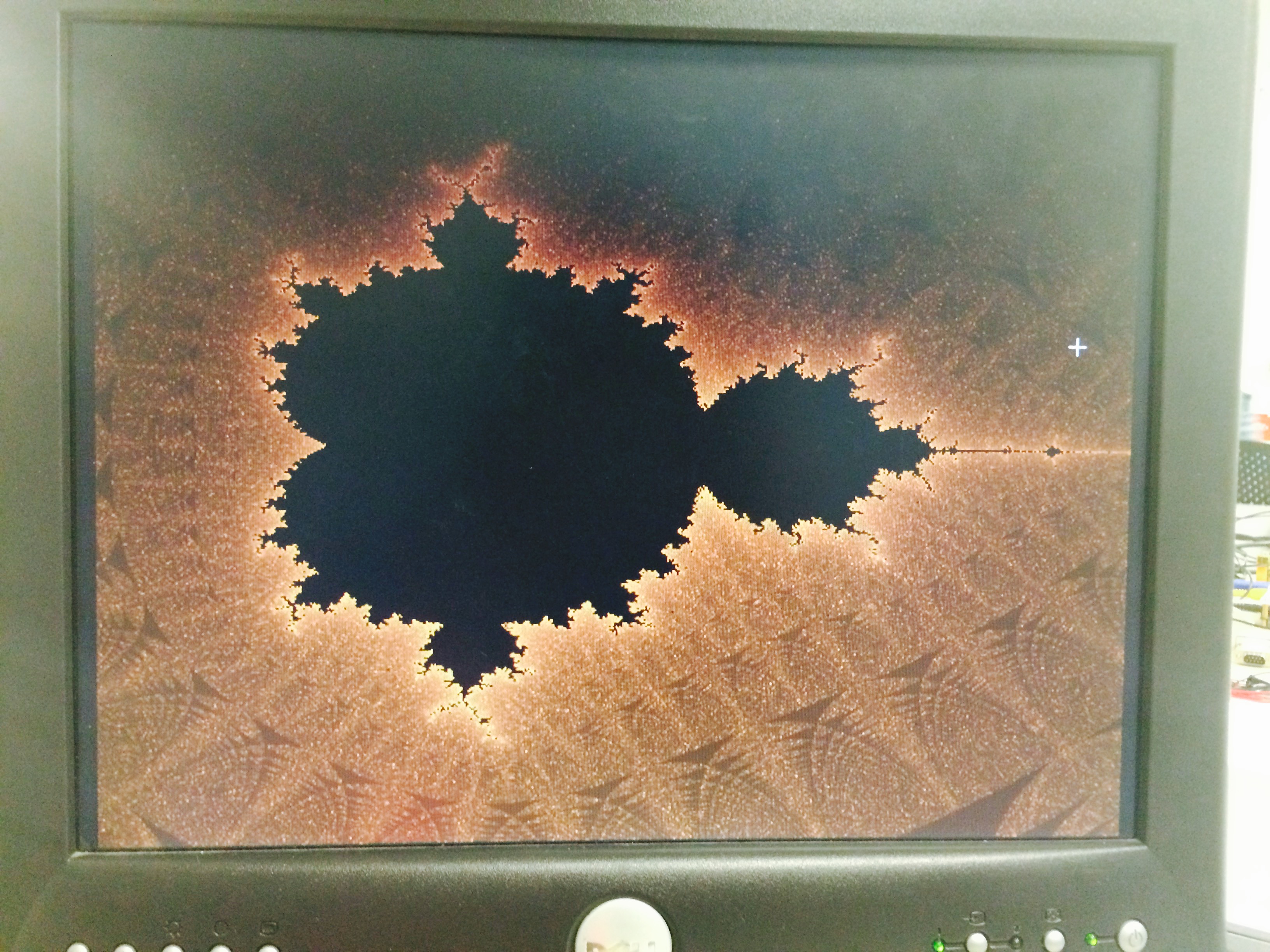 |
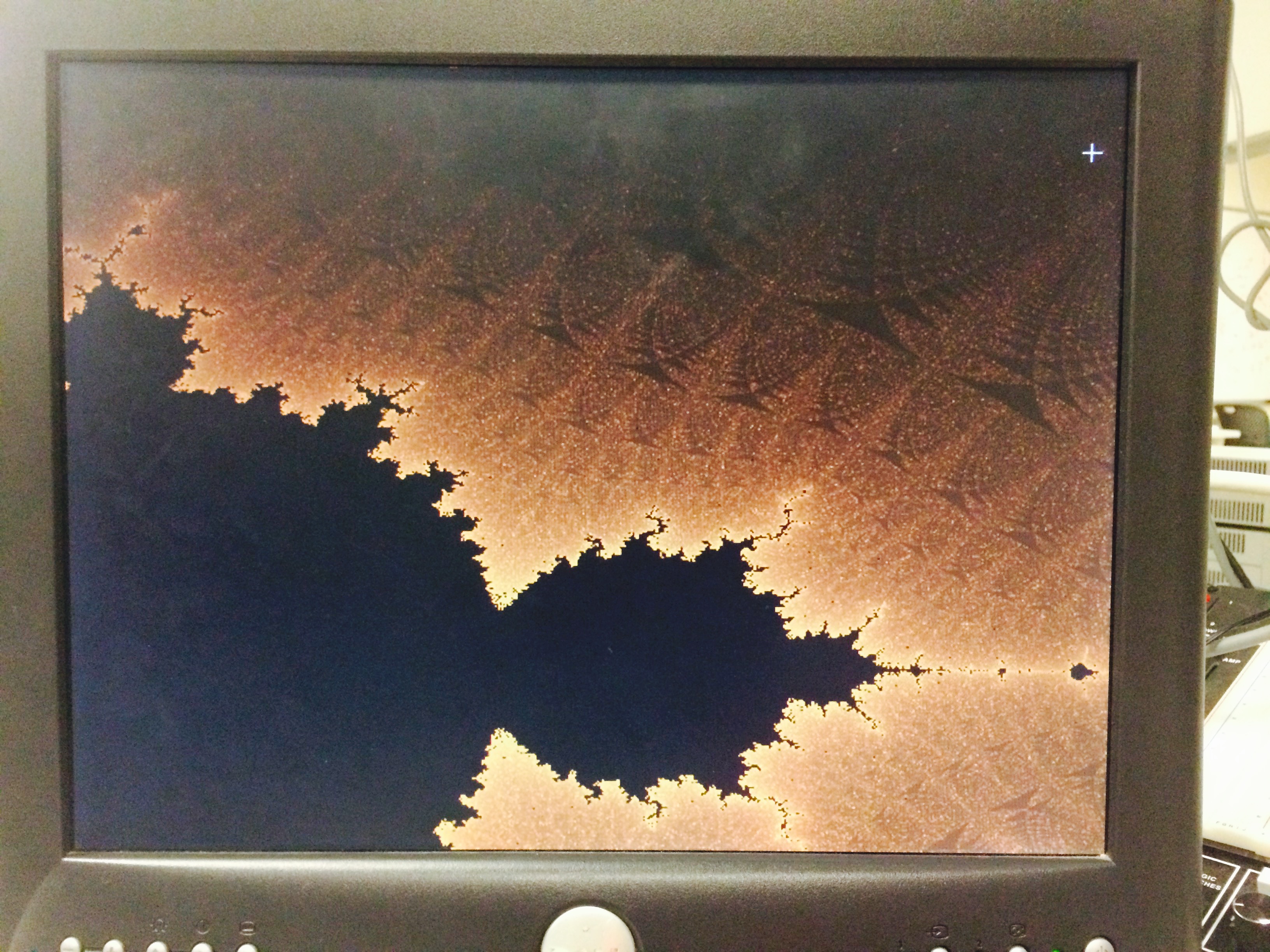 |
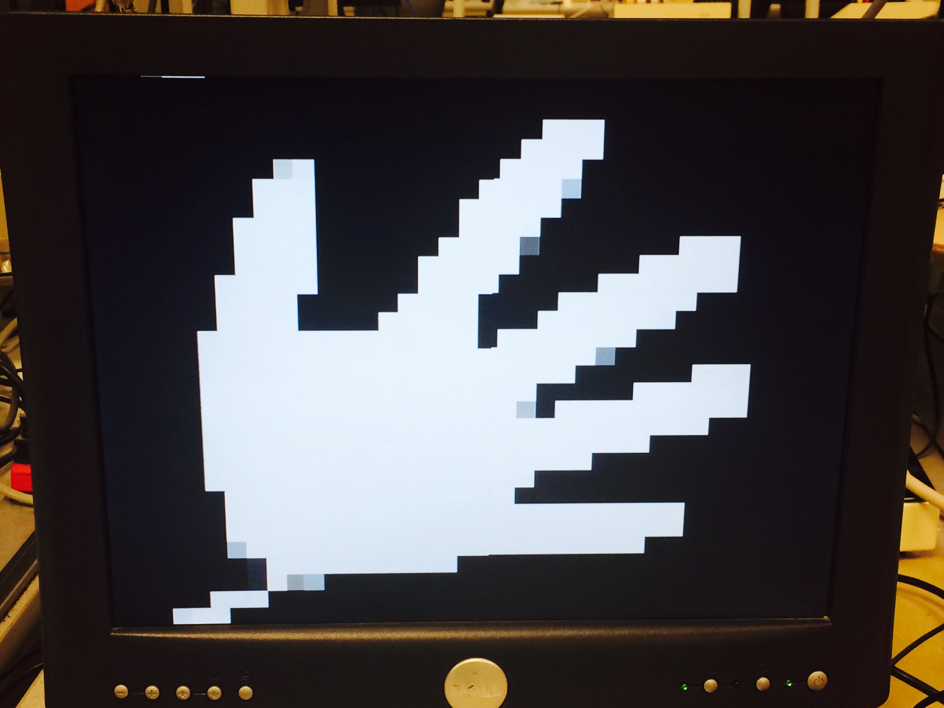 |
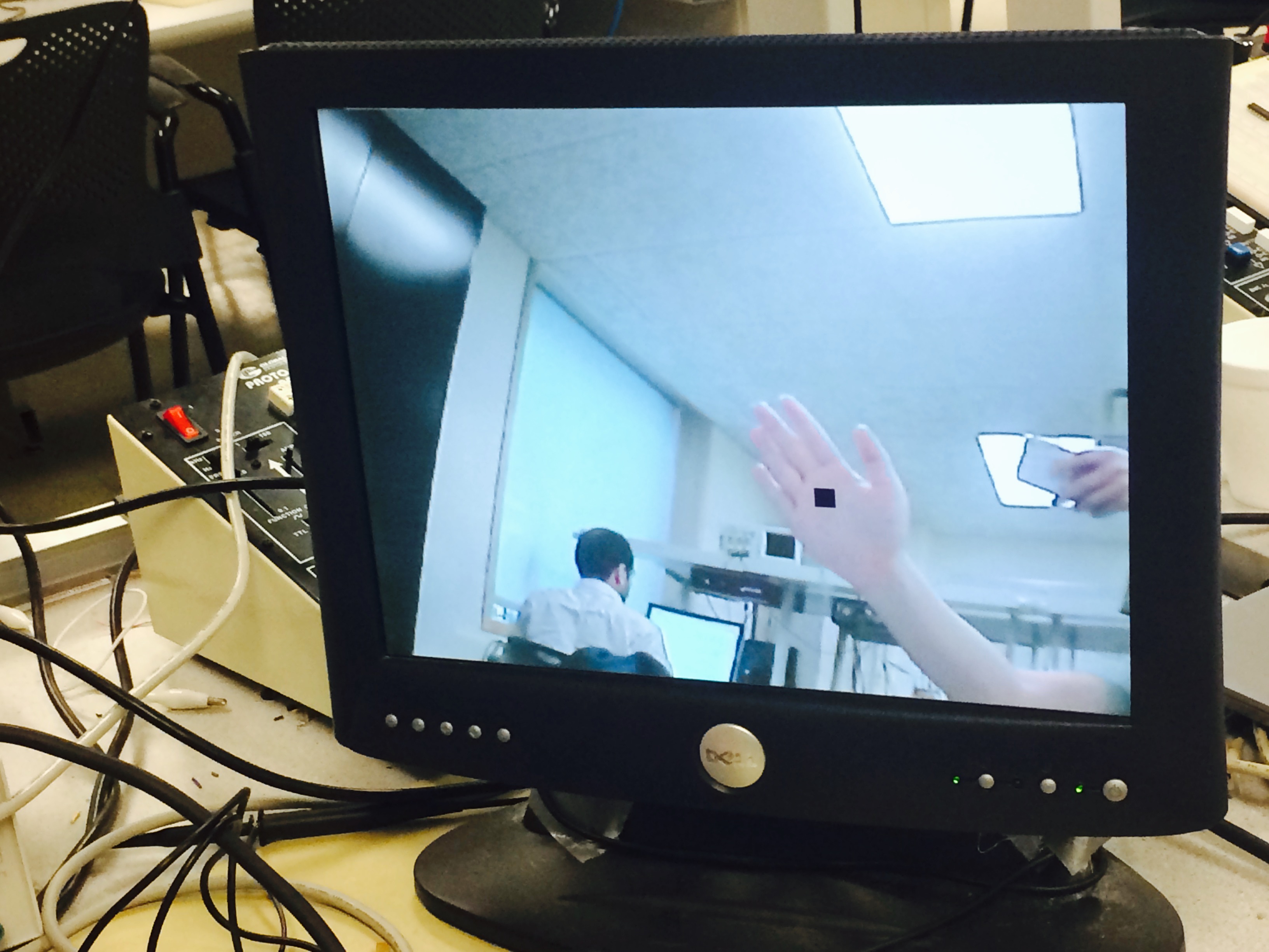 |
• Safety in the Design, Interference, and Usability:
There are no major safety hazards in this design. The system also does not interfere with other projects. Cause the hand tracking cursor was trained first at reset, so unless a big chunk of skin color moving in the background, the hand tracking would not be interfered.
This project is usable by anyone with bare hand. One thing to note is that users are recommended to wear long shirts or wear a watch or anything that can block the skin color on wrist.
Conclusion top
In this project, we successfully prototyped a platform which allows players to interact in real-time with Mandelbrot Set. The system can correctly interpret the user’s intention based on the geometric features of a hand and respond to user's gestures at video rate. In addition, the change rate of the image features is greatly stabilized, providing a smooth visual effect.
Still, this prototype can be further improved in terms of the details in the Mandelbrot Set. Currently, the Mandelbrot Set has a limited zooming depth because the bit width of the complex numbers in Mandelbrot Set is set to be only 27 bit. More color details of the Mandelbrot Set can be shown without artifacts if we can better utilize the hardware resources (memory) in the FPGA by doing calculation at higher clock rate.
Human-machine interaction would be an even more interesting focus to work on. In order to make the panning more stable, we need to tweak for the best overall performance of downsampling ratio and the cut-off frequency of the spatial low-pass filter. Meanwhile, we find out in experiments that the light condition in the room would affect the correctness of skin-color detection. Other image processing methods such as mean filter can be tested to see their effectiveness. For image zooming, we can try to get a more accurate measure of the hand area by extracting more information out of the irregular shape of the hand. This would certainly be challenging as it increases the computation workload for the FPGA. We can also limit the distance range between the camera and one’s hand so that we can eliminate the confusion between a small hand projection and half of a hand within camera range when the hand is very close to the camera. After these improvements, it would be able to present better effect if zooming center is at the hand’s centroid instead of at a corner of the VGA screen.
The link to the video demonstration of the project is here.
Appendices top
The zip file of the entire project can be found here.
The top level module is DE2_115_TV.v
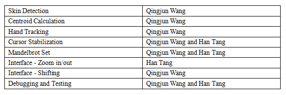
Tasks Split under each member :
Acknowledgement :
We would like to thank Professor Bruce Land for his thorough and insightful guidance in ECE 5760, and for all the suggestion and assistance provided to our final project . We would also like to extend our gratitude to our TA Deepak Awari (dma234) who assisted us in every lab throughout the semester.
References
- Altera DE2-115 User Manual
- Realtime Face Tracking - Perspective Projection on FPGA
- Fruit Ninja with video tracking
- YUV colorspace .
- Nerdy Stuff, Multi-pipelined Mandelbrot Set
- XO Vision HTC 231x CCD Bullet Camera
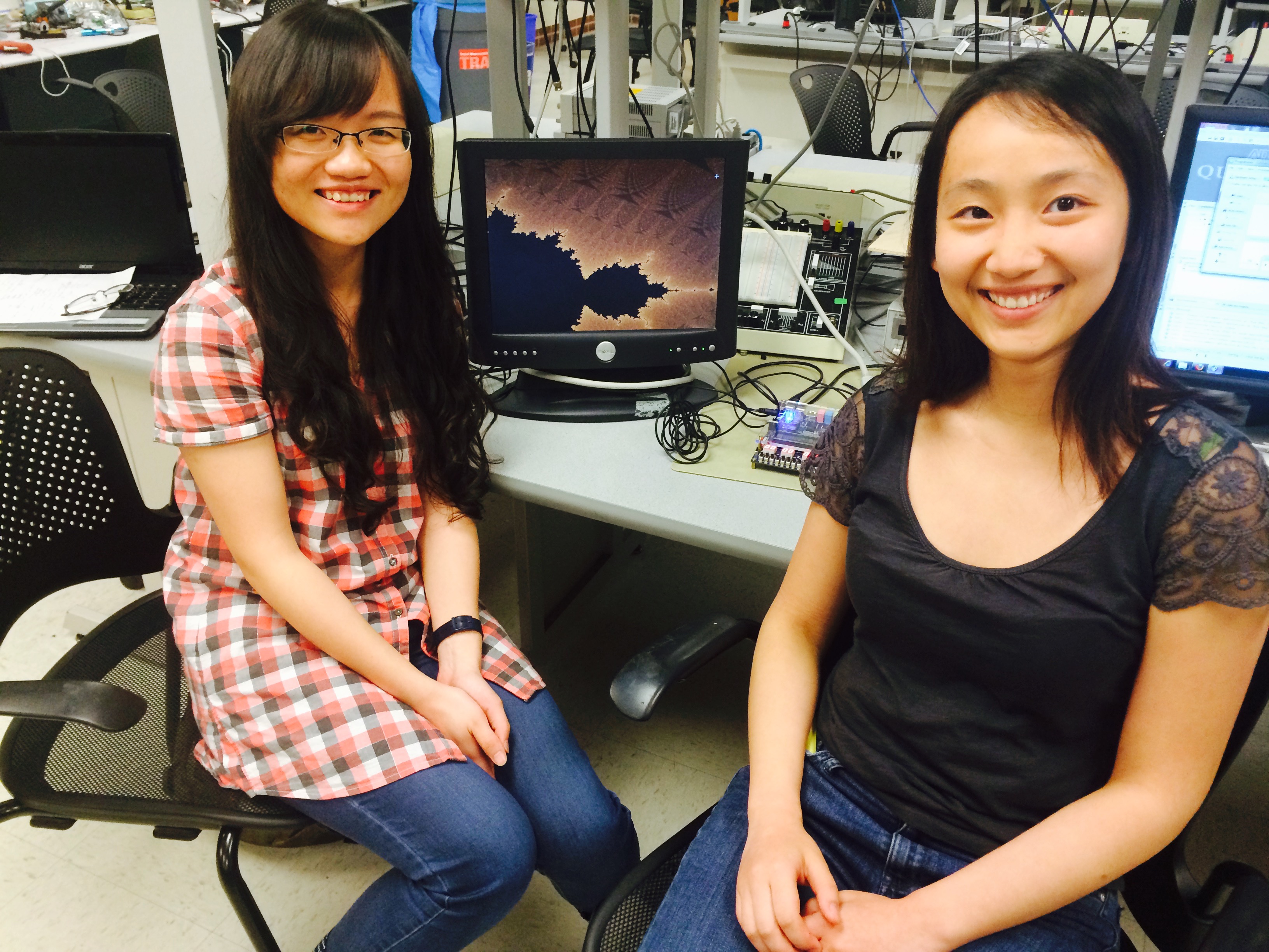
About Us top
 |
Qingjun Wang
M.Eng Student, 2015
Electrical and Computer Engineering
Interests:
Embedded System, Optoelectronics |
 |
Han Tang
M.Eng Student, 2015
Electrical and Computer Engineering
Interests:
Embedded System, Parallel Computing |