Introduction top
This is a finger detection based project using a camera to detect the user finger's location relative to the vga screen and display a cursor on the screen to reach the effect of a pseudo touch screen. A chess board is displayed on the VGA screen and by touching the chessboard, the user could place a piece on the chessboard to play the game 'five in a row', by connecting any five piece in a row, the user could win the game.
The idea is to have a NTSC camera pointing right toward the screen, capture the video when and using morphological filtering to get rid of the errors, and get the location of the finger tips. If the cursor stay still at the same location for a certain period of time, a piece will be displayed on the nearest chess board intersection. All the chess position is sent to the NIOS system to decide which side had win the game.
Highlevel Design top
Rationale and Inspiration:
Inspired by the famous Xbox body sensor game and some previous ece 5760 final projects of tracking the body movement to control the game, we decided to make a video game controlled by the finger location detected by the camera to simulate the effect of a touch screen. Most of the relavent previous course project use only the color to find and identify the desired object, we take the advantage of that and try to find the fingertip location.
In this game the player will be pointing on the VGA screen and there will be a green cursor showed up on the nearest intersection point of the chessboard shown on the screen. When the player deciede to place a piece on this location, they just need to stay at the same location for 2 sec. If either side of the player had an unbroken row of five pieces horizontally, vertically, or diagonally, this player win the game. The game will reset after pressing Key0.

Figure 2-1: Highlevel Design Diagram
Background Math
Skin Detection
As mentioned in "Face segmentation using skin-color map in videophone applications" by Chai and Ngan, A skin color map Y_Cb_Cr is derived and used to detect pixels that appear to be skin. The renge of Y Cb and Cr that are most relavent to skin are:
mY > 80
85 < Cb < 135
135 < Cr < 180

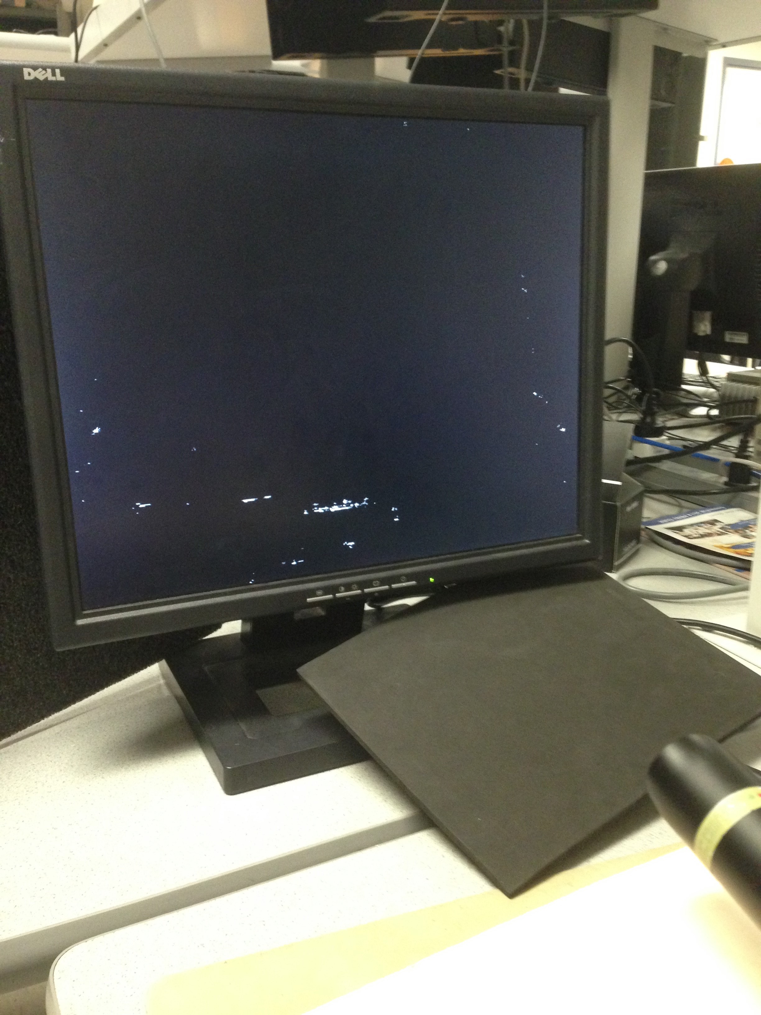
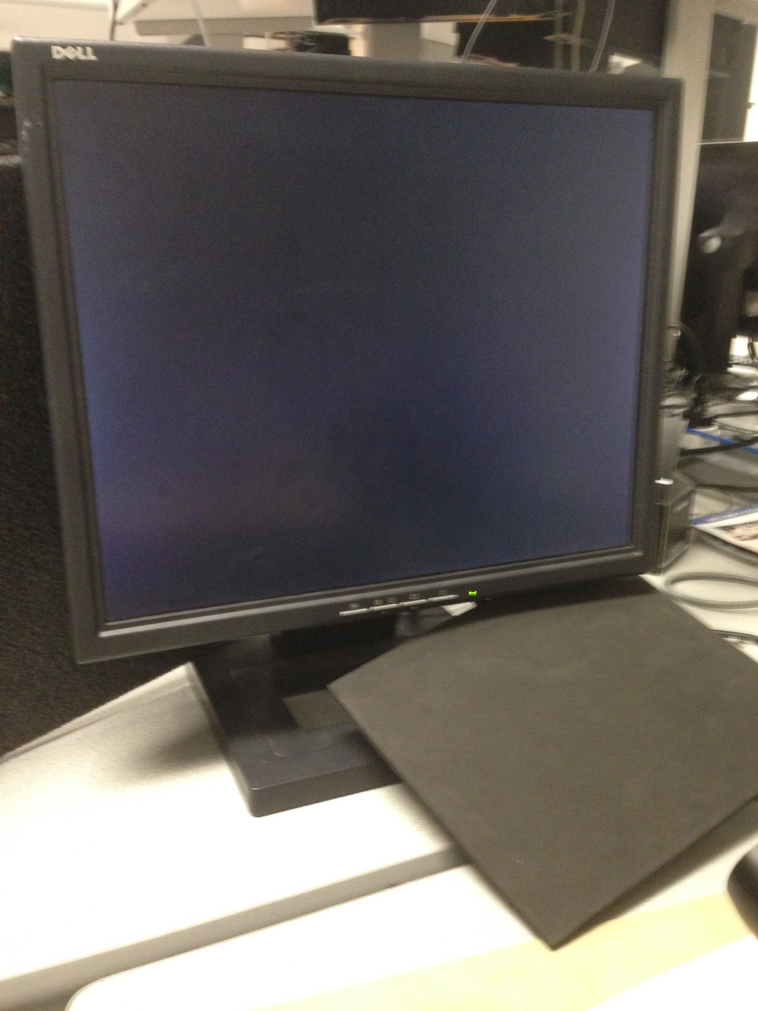
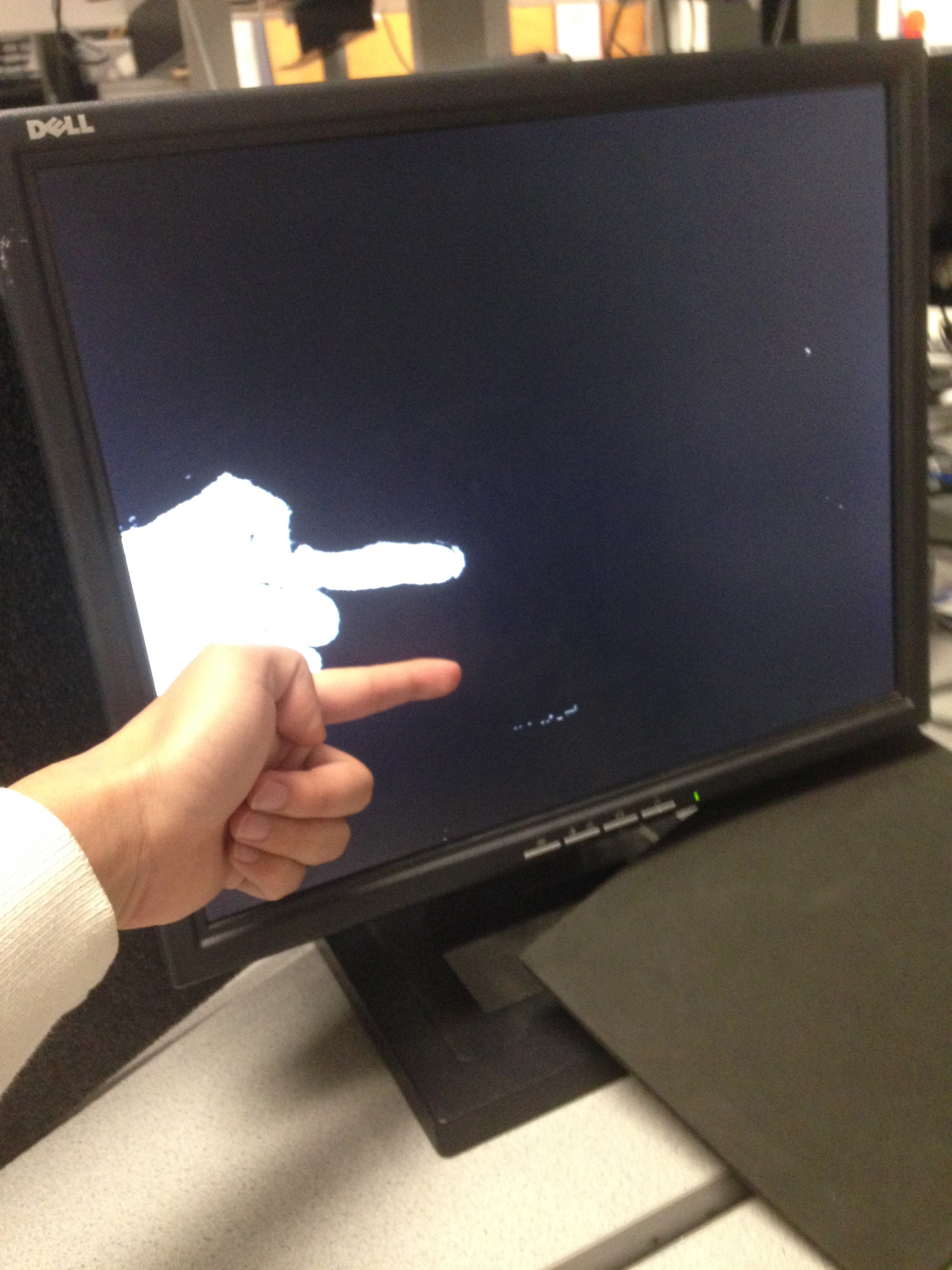
Figure 2-2: Picture After Thresholding
Overall, this skin detection thresholding method elimate most of the background information and leave a recognizable binary image with hands and some noise. In order to run the fingertip recgonization algorithm, we need to first separate the hand with noise and other small irrelevant parts.
Morphological Filtering
As we could see from the detected images, the irrelevant part and noises are much smaller than the hand detected, and the hand detected may not be fully detected as a whold piece, several black holes may show up because of the shadow. As a result using morphological filtering will help us get rid of the noise and full the missing part of the hand relatively well.
Dilation and Erosion
Erosion and dilation are two basic operators in morphological filtering. Erosion and Dilation of a binary image A by the structuring element (kernel) B are defined as:
Figure 2-3: Erosion
Figure 2-4: Dilation
Erosion helps to get erode away the pixels around the boundary of the image pixels in A which fit the shape of the kernel B. Dilation will enlarge the image in A by a scale of kernel B. These two operators are used to generate a more complex morphological operator called Opening and Closing.
Opening and Closing
Opening is the dilation of the erosion of the binary image A by a kurnel B, which means that A is first eroded by B, and then dilate the result by B again. Closing is an completely opposite operator which is the erosion of the dilation, meaning A is first dilated by B and then go through a erosion by B. Both of the equation could be shown as below:
Figure 2-5: Opening
Figure 2-6: Closing
The effect of opening and closing are shown below. Opening is to get rid of the pixels which does not fit the shape of the kurnal, for our perticular case since the niose are much smaller than the hand detected, so if we use a kurnal which is slightly bigger than the biggest noise, most the distractions on the screen will be elimiated, while the shape of the hand will be remained. However, since the irrelevent part is larger than the niose, if we try to use a kurnal bigger than these parts, the shape of the hand will be deformed and it will be hard for the further analysis to find the finger tip location. After the opening part is done, the closing part will be used to fill the unconnected piece inside the detected hand skin pixels.

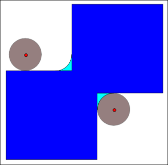
Figure 2-7: Opening Effect Closing Effect
In our design, we use a kurnal of a 5*5 square for both opening and closing with its origin at the bottom right corner. The 5*5 kurnel will get rid of all the noise while have the hand part remain a similar shape. Althrough there are still some irrelevent pixels remained, these parts are all formed in several compelete pieces , and are much smaller than the hand part which could be ignored in the finger tip detection method we used later.
Finger Tip Location
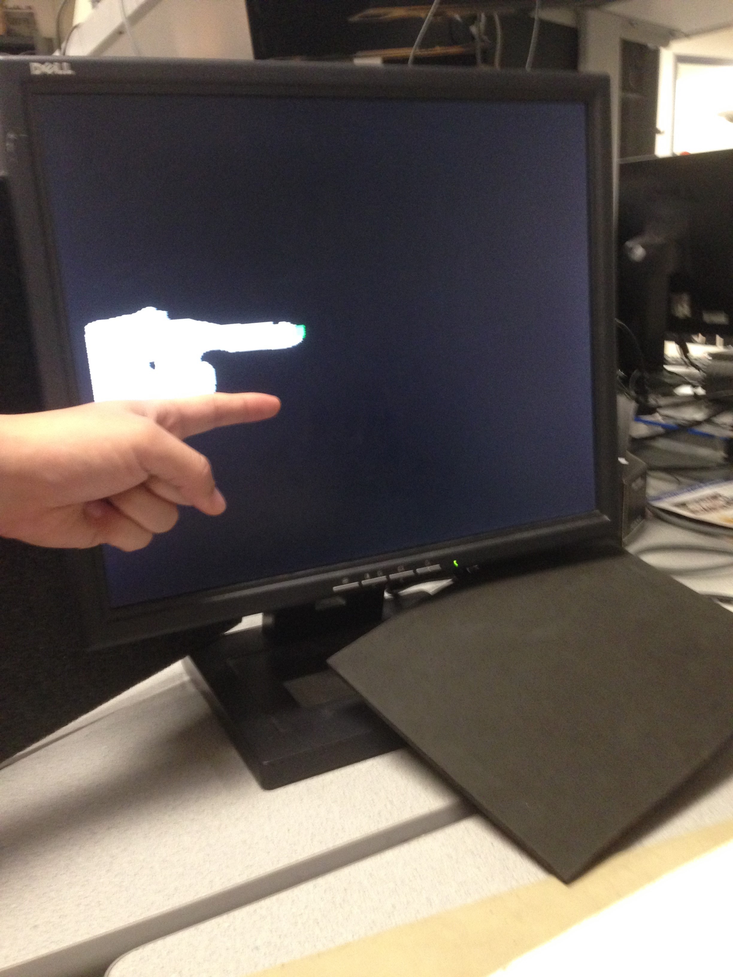
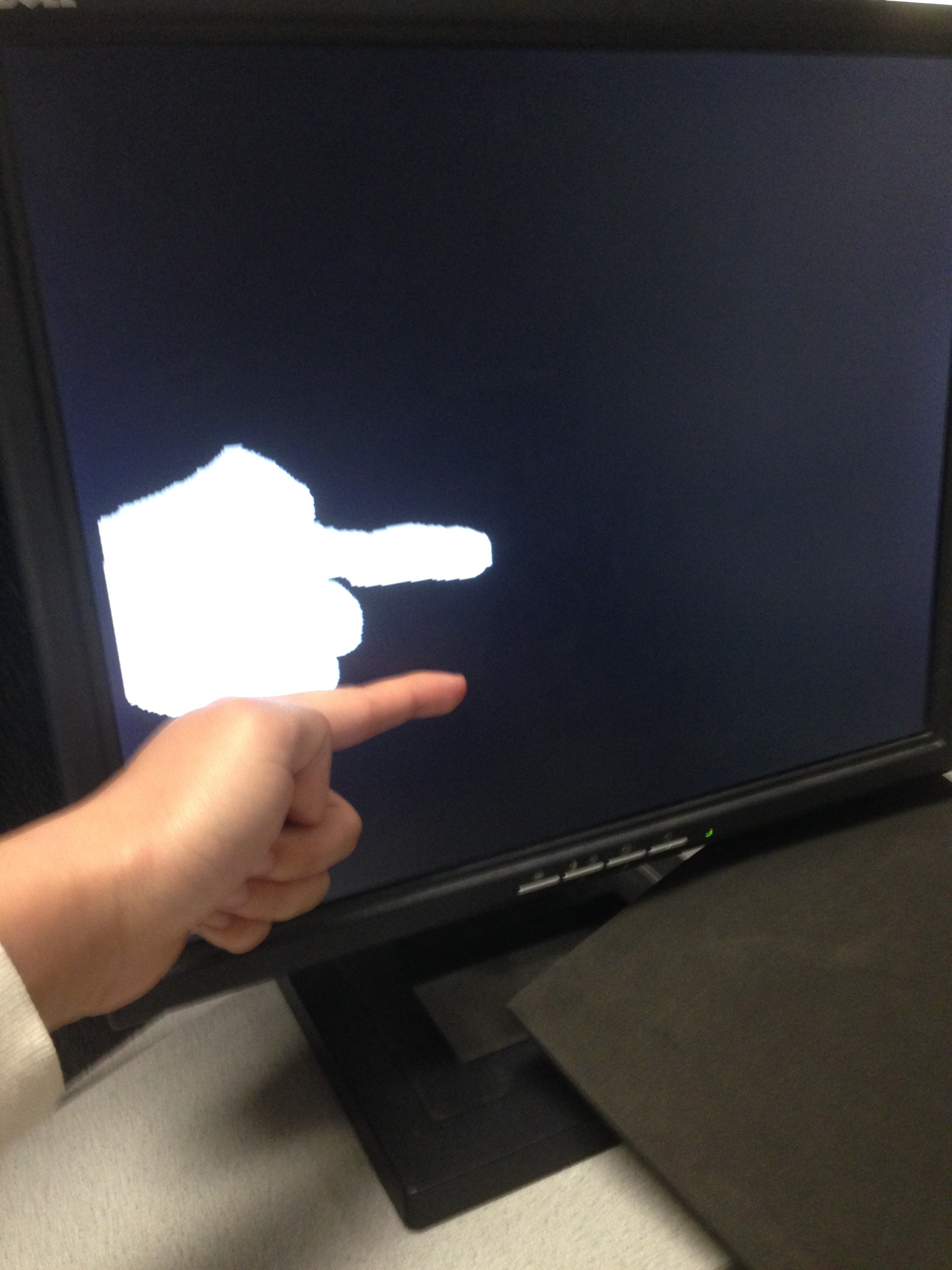
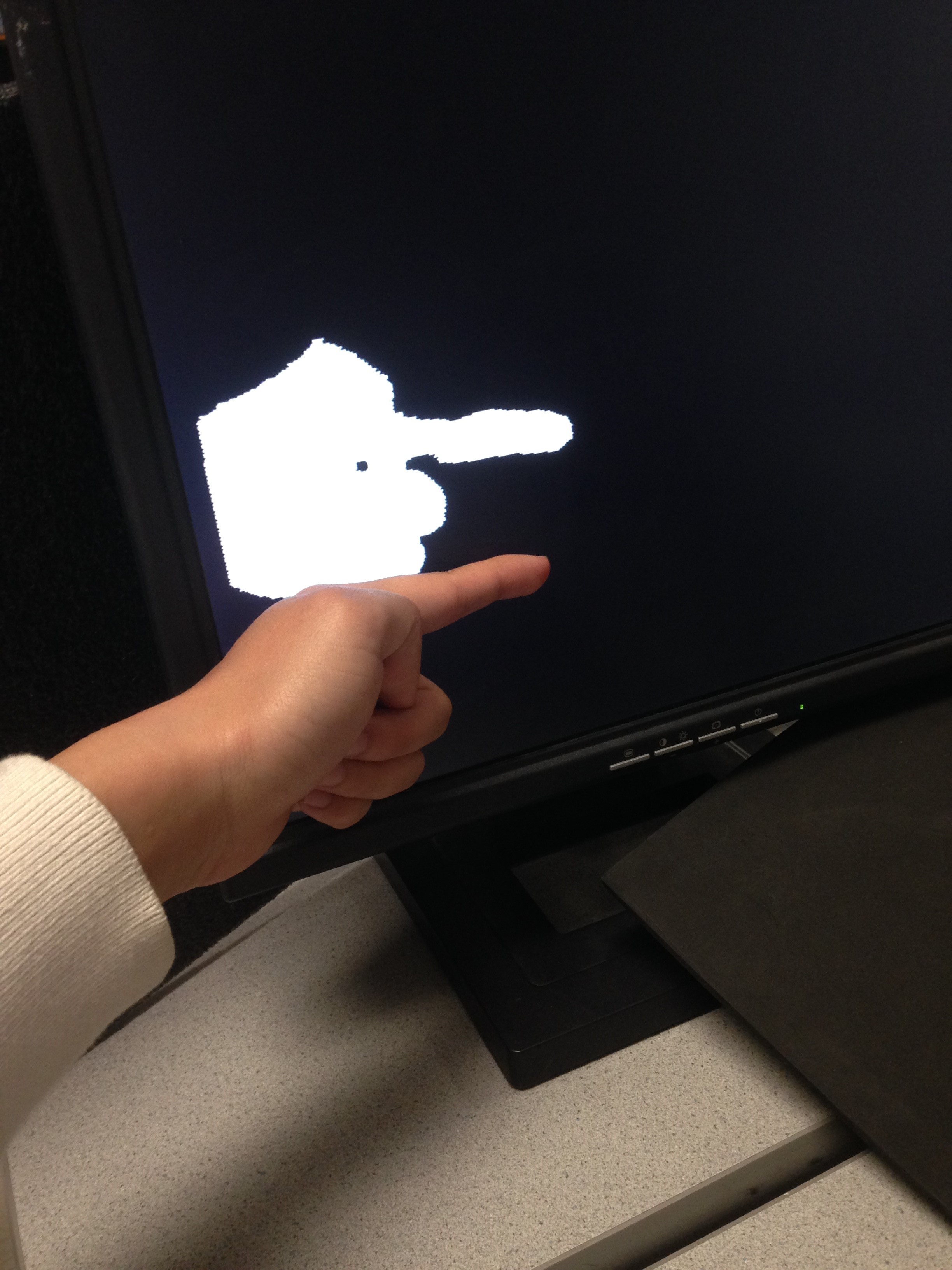
After the filtering, the finger detected is shown below, we figure out that the span of the skins in X axis is longer than the span in Y axis. So by comparing the span in both axis we can figure out if the hand is pointing horizontally, vertically, or diagonally. After that, we project all the skin pixels on the X and Y axis respectively, and try to find the feature to locate the finger tip.

Figure 2-8: Hand Picture after filtering

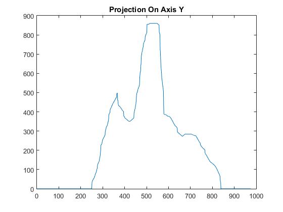
Figure 2-9: Projection On X Axis Projection On Y Axis
As depicted in Figure 2-9, we can see that on the axis where the hand is pointing to (X at this case), there are two location where the skin pixels disappears, which happens to be the finger tip location and the wrist location but it is hard to figure out which is which. It is easy to see that the place had the maximum plxel projection is the knuckle and the finger tip is the place which had the longest distance to the knuckle. So the X coordinate of the finger tip could be located
After locat the X coordinate we cound project the pixels, whose X coordinates are around the finger tip x coordinate, on Y axis again and there will only be the projection of the finger instead of the whole palm. This projection result is shown below, we can see that the maximum place appears to be the finger tip location on Y axis.
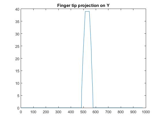
Figure 2-10: Finger T projection on Y Axis
The result of the finger tip detection is first tested in MATLAB (code), the result is shown below:
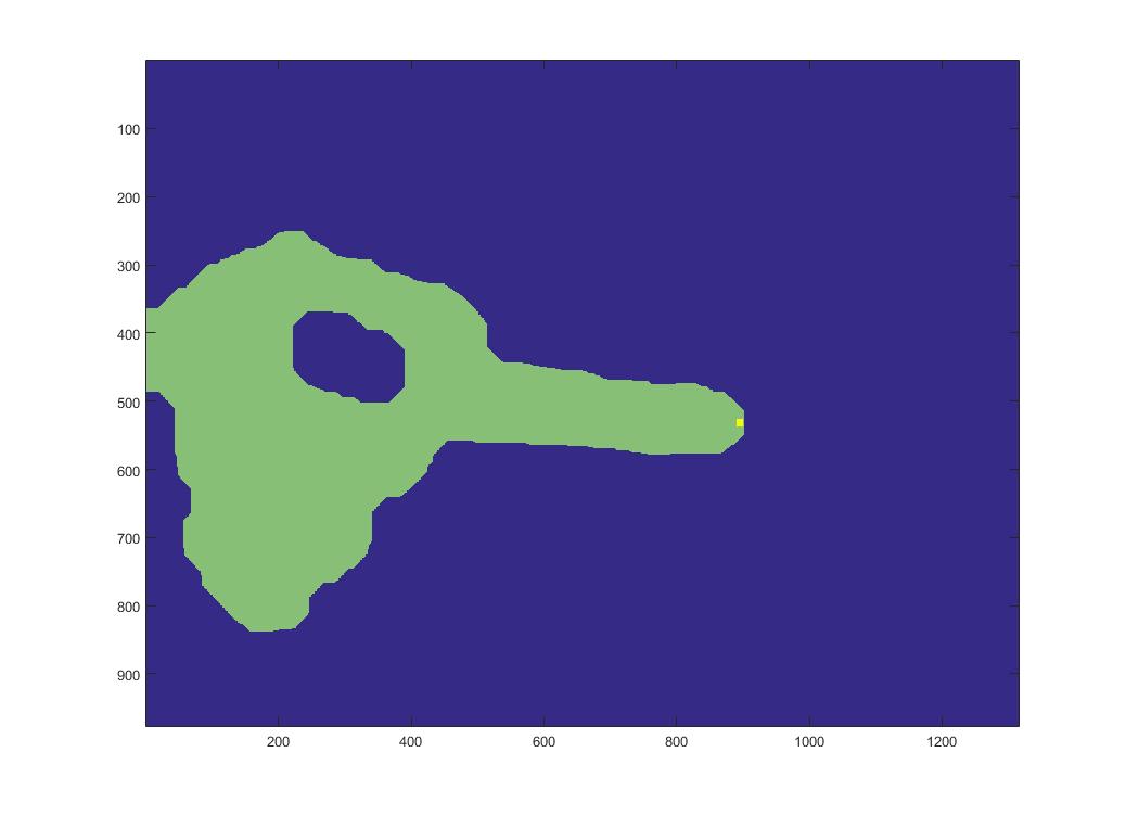
Figure 2-11: Finger Tip Location Result
Design top
Hardware Design
NTSC Video Convertor
NTSC Camera signal is decoded through the DE2-115 TV Decoder based on Altera University Program Example, and the reference is shown in "Intellectual property consideration' part. The FPGA took in the video signal ---> decode into YUV signal ---> store the data in SDRAM and also transfer into YCbCr space for furthur processing. The Diagram for TV Decoder is shown below:
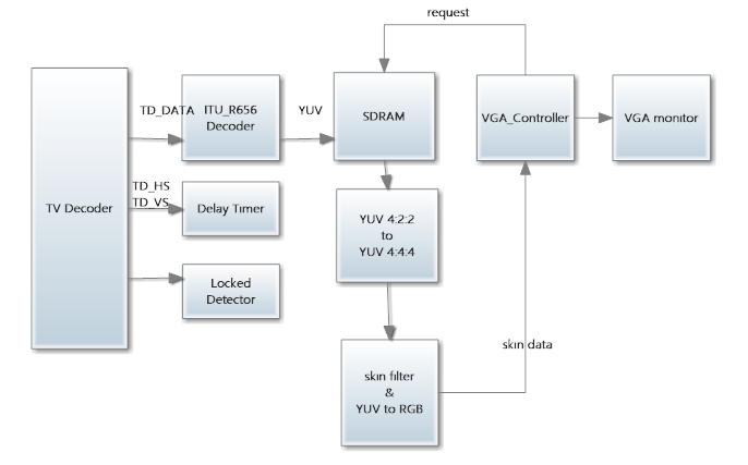
Figure 3-1: DE2-115 TV Decoder Diagram
Cited from: Previous ECE 5760 Final Project: Hand Tracking Mandelbrot Set
Video Data Storage
After decoded and tranformed into YCbCr format, the skin detection threshold is used to transform the image into binary format. In order to store this binary image and the images, we used the 2-port RAM generated by M9k blocks, one port for read only and one port for write only. Both the reading and writing address of these 2-port RAM use the combination of VGA_Camera Address signal which will swap through the whole screen row by row.

Figure 3-2: RAM Address
In order to do the morphological filtering several times, we need to store the intern image data complete by the previous filter. However, as we need to do the filtering 4 times, there will be totally 5 pictures at each process cycle, and FPGA does not have enough M9K blocks to store 5 640 x 480 binary images at the same time. As a result, we only use two RAM to reach the same effect use the data inside one of them as input image and the other one to store the output data. Two RAM will take turns acting as input and output buffer, The block diagram of this part is shown below:

Figure 3-3: RAM Data Transfer Diagram
After the Video is modified by the filter, the output of the last RAM will be used to build the histogram in both X and Y axis, which are also stored in RAMs. This time the read address will use the X coordinate and Y coordinate of the pixel respectively and the write will be the X & Y coordinate two time cycles before, because it will take two cycle to get the previous histogram data from the RAM.
When the histogram of the whole picture is built, we scan through the whole histogram to find the place where the skin pixels appear and disappear, as well as the place where it had the most skin pixels detected. Then the span of skin on each axis will be compared. On the larger axis, the appear or disappear place which had larger distance to the max skin detected place will be treated as one of the finger tip coordination. After knowing this location, the image pixels around this first found location will be projected on smaller axis, and the location where most skins are detected will be treaded as the other coordinate for the finger tip.

Figure 3-4: Finger Tip Detection Diagram
Morphological Filtering
The Morphological Filgering need to store the exact size of the image around the center point to compared with the kurnal. So, as we have a 5 x 5 Kurnel, a shift register of size 5 is used to swap throughon all lines, which updates every time period. Another buffer, column Buffer is combined by 4 same column which updats every time 640 cycles (exact time period to swap through the line), then these buffers will store the top right 25 pixel information in a 5 x 5 pixel renge. The data in these buffer will be compared with the kurnel to do the morphologicla filtering. The diagram of this part is shown below:

Figure 3-5: Morphological Filtering Diagram
game side
Position Rounding
The chess grid we have is a 16 by 16 board. The x coordinate in chessboard is 0 ~ 15, which maps the coordinate in VGA 80 ~ 560. The y coordinate in chessboard is 0 ~ 15, which maps the coordinate in VGA 0 ~ 480. However, human player could never hold its finger very stably at the accurate position, hence we need to do the rounding. After rounding, mapping of fingertip position on VGA display and chessboard goes as following table:
| Board X coordinate | VGA X coordinate - 80 | Board Y coordinate | VGA Y coordinate |
|---|---|---|---|
| 0 | others | 0 | others |
| 1 | 16~48 | 1 | 16~48 |
| 3 | 80 ~ 112 | 3 | 80 ~ 112 |
| 4 | 112 ~ 144 | 4 | 112 ~ 144 |
| 5 | 144 ~ 176 | 5 | 144 ~ 176 |
| 6 | 176 ~ 208 | 6 | 176 ~ 208 |
| 7 | 208 ~ 240 | 7 | 208 ~ 240 |
| 8 | 240 ~ 272 | 8 | 240 ~ 272 |
| 9 | 272 ~ 304 | 9 | 272 ~ 304 |
| 10 | 304 ~ 336 | 10 | 304 ~ 336 |
| 11 | 336 ~ 368 | 11 | 336 ~ 368 |
| 12 | 368 ~ 400 | 12 | 368 ~ 400 |
| 13 | 400 ~ 432 | 13 | 400 ~ 432 |
| 14 | 432 ~ 464 | 14 | 432 ~ 464 |
| 15 | 464 ~ 496 | 15 | 464 above |
To interpret this, the pattern here is, if (VGA_coordinate - 16) / 32 == (VGA_coordinate) / 32, it should be rounded up, otherwise, it should be rounded down. Finding this pattern is easier to write the code, but it takes longer for the compiler to synthesize, and it’s less stable according to our experiment. The easiest way to interpret this is to have this look up table hard-coded in verilog, and that’s exactly our way of implementation. It’s harder to write the code, but it’s more straight-forward, it takes shorter time to compile and it’s more stable.
Position sampler:
The objective of position sampler is to decide when the human player has confirmed to place a piece at certain position of the chessboard. To accomplish this, we built a sampler running at a clock of 500 milliseconds. It samples the position of rounded-fingertip every 500ms, if the position appears to be the same for 4 times in a row, plus the raw fingertip position is actually inside the chessboard range, it decides human player has confirmed a move at that position. The sampling time and period is carefully chosen. Running sampler slower, or having more samples makes sampler more stable, but if one sample is off, it needs to restart sampling and it’s harder for user to actually place the piece. Running sampler faster, or having less samples, in contrast, makes sampler less stable, and unwanted false move would happen.
After the sampler finds a firm press, it generates a pulse for one cycle to simulate a key-press, which drives the state machine to go next state.
State Machine in game side:
The following is the state diagram of state machine.

Figure 3-6: state machine
The first state, or the state after resetting, is used to initialize the grid. It essentially clears all counters and registers for moves, then load the piece type for the first turn, and draws the grid to VGA buffer. Then it jumps to next state to first circle initialization.
First circle initialization state sets the position to draw the piece (circle). It waits until a key has been pressed, and no piece has been placed in the position it wants to draw. The action to jump to the next state happens at the falling edge of key press. Before jumping to the next state, it registers the move of human player, and flips the turn (White or Black). The next state is to draw the first circle.
First circle state draws the first circle and acknowledges to Nios processor indicating the state machine has confirmed the move of Nios, and performed all necessary steps to process that (Register the move, draw the piece nios played, etc). The background math is straightforward, it simply uses the equation of (x-a)^2 + (y-b)^2 <= r^2. For white pieces, light all pixels inside the circle, for black pieces, light boundary pixels only. Before the circle has been completely drawn, it stays at this state. Otherwise, if one side has already won the game, it jumps to the state of one side winning, if no one wins, it jumps to the state to wait for the move from Nios. If currently it’s in human vs human mode, this state skips to play with Nios and directly goes back to first circle initialization state.
Wait for Nios response state simply waits for the response from Nios processor, it hangs over until Nios processor has performed a move. It jumps to confirm the move of nios state after Nios has responded.
Confirm the move of Nios state processes the move from Nios. It registers the move of Nios, then sets the position of piece to be drawn on the screen. The it jumps to second circle state.
Second circle state does basically the same thing as first circle state. It simply draws a circle, after the circle has been completely drawn, it jumps back to first initialization state.
Nios System:
The nios system was built on Qsys. It uses Nios II processor, running at 50MHz. Instruction and data is stored in a piece of M9K block memory. Besides that, there are several Parallel I/O ports for communicating with state machine. The qsys file could be downloaded here. The following chart explains the connection of Nios system with state machine.
| State Machine Side | Nios System Side |
|---|---|
| CLOCK_50 | clk |
| KEY[0] | reset_n |
| {x_sw,y_sw} (x,y coordinates on chessboard) | xy_sw_from_fpga (input) |
| piece_type (white piece or black piece) | piece_type_from_fpga (input) |
| key1_pressed (pseudo key press by sampler) | key1_pressed (input) |
| white_win_bit_from_nios | white_win_bit_to_fpga (output) |
| black_win_bit_from_nios | black_win_bit_to_fpga (output) |
| nios_responded | nios_responded (output) |
| nios_move_x | nios_move_x (output) |
| nios_move_y | nios_move_y (output) |
| acknowledge_to_nios | ack_to_nios (input) |
| human_human_mode | human_human (input) |
Nios system essentially behaves as a judge and a machine player (it’s just a player performs random legal move, not an artificial intelligence). In human vs machine mode, it records the move of human player, judges the board, then perform a random move, and tells state machine it has responded. Then it waits until human player performs next move. In human vs human mode, it skips perform a random move part, only behaves as a referee. When the game comes to an end, it tells the state machine the end condition has been triggered, and it hangs over. More details about how Nios systems could be found at software implementation part.
One side win image:
The leftmost 80 pixels (x 0~80, y 0~480) are left blank for showing “white wins”, while rightmost 80 pixels are for black. The image showing the text information is pre-stored in a ROM initialized by a mif file. The ROM is a M9K Block generated by Mega-wizard. When one side triggers winning condition, VGA controller reads the data from ROM, otherwise, it reads data from VGA buffer, which leftmost 80 pixels and rightmost pixels are left blank. To generate the mif file, we used paint to write the text first, then reverse the color, then uses a MATLAB script to convert that. Before converting the image to mif file, we need to threshold the image first. The MATLAB script could be downloaded here.
Software Design
The software for game side is mainly the c code for Nios processor. It is acting as a referee as well as a machine player who plays random legal move. Though there is no concurrency problem in this specific project, and the program is single threaded as well, we have ported protothreads to the nios system, so changing the parameter in real time becomes possible. Also it prints out some information, not only for debugging purpose, but also makes it possible for player to go through moving history to review the game. The flowchart of Nios software program is shown below.

Figure 3-7: Nios Flowchart
For more details, please refer to the appendix of our source code.
Results top
Performance:
The system we built is reliable and stable. It is able to be accurate to fingertip level to place a piece on the board. Below are several examples of finding the fingertip on the screen.
Before and After Filtering
Below is the result of our erosion module. The left is the raw image with noise, right is after erosion perform. It efficiently suppressed the noise.
Finger Tip Found
After performing a series of morphological operation, or to be more specific, erosion + dilation (opening), dilation + erosion (closing), noise has been properly removed and hand shape has been well maintained. Example pictures are shown below. The sequence of image is, from left to right, raw image -> erosion -> dilation (opening) -> dilation -> erosion (closing).


Raw Image Erosion Dilation Dilation Erosion
Also, the machine player Nios is playing is able to perform legal move and judge the game even on a complicated base. Below are two example pictures for white wins or black wins.

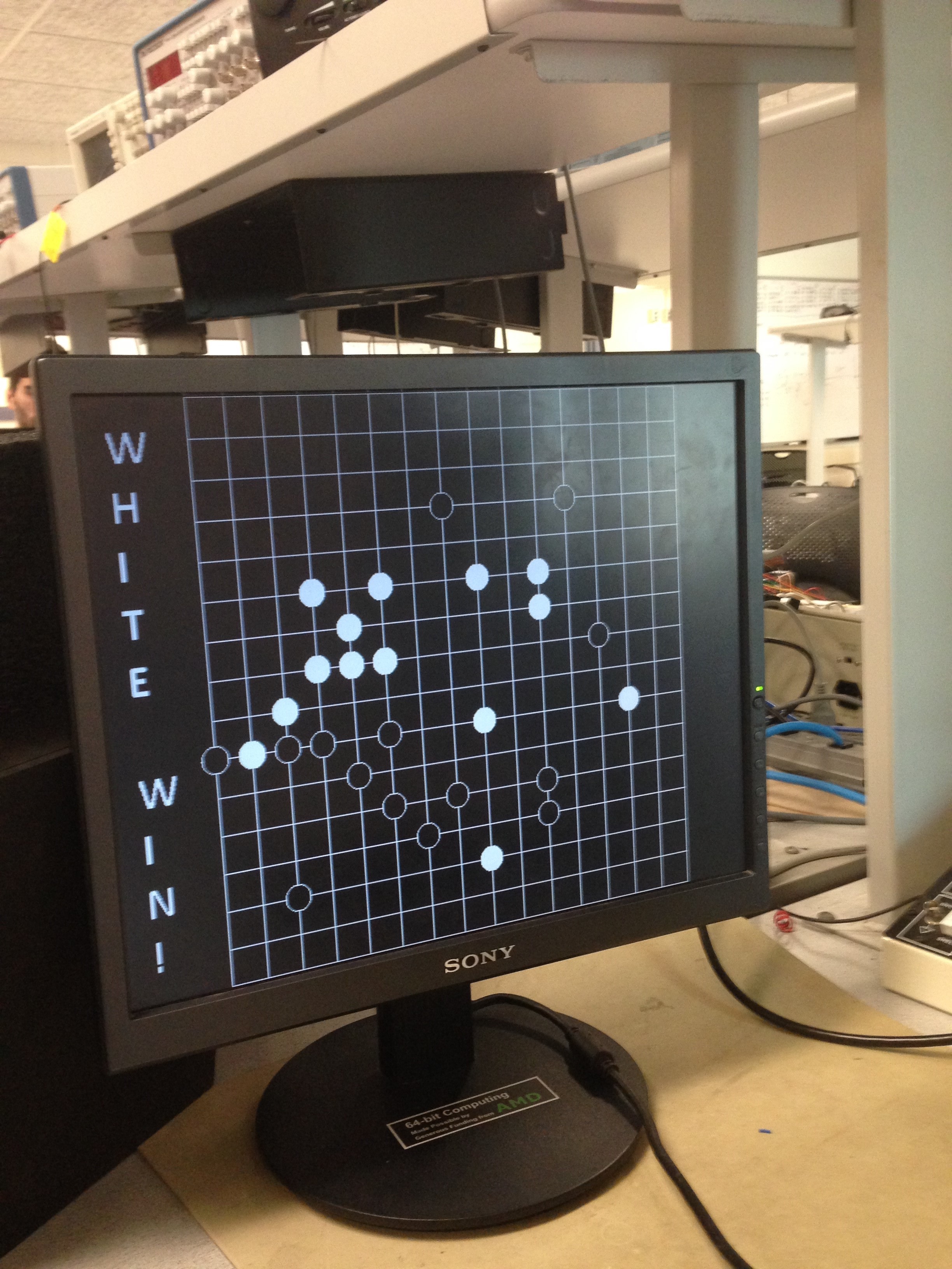
Black and White Wins
However, flaws of system include:
1. boundary location is very hard to place a piece.
2. Noise might cause a false move, but the chance is extremely small.
3. Users must wear long sleeve to play the game. Skin of other parts of body, including elbow, face, etc, could not be in the camera.
Savety
Our project only consists of a camera, a DE2-115 FPGA board, a monitor. The system does not have any safety issue.
Usability
The rule of five in a row game is very straightforward, and the idea of placing a piece simply by pressing the finger on the screen is very easy to understand. So generally the project is very user-friendly. But the user must obey the following two rules:
1. The user could not block the camera, or have big skin-colored objects being shot by the camera. Because the system is based on the camera and skin-detection.
2. The user must hold its finger for certain amount of time to place a piece.
Conclusions top
We have met all requirements as we proposed the project. Also, our fingertip detection is reliable because the noise is maximally suppressed and the shape of hand is maximally guaranteed by a series of morphological operation. The tip of finger only has 100 pixels or so, but the VGA screen has 640 by 480, more than 300,000 pixels. Being accurate to fingertip-level means the result is accurate to 0.1% of the screen.
Improvements we could do is:
The machine player only performs random move. Since the communication of Nios and state machine has been fully built, if more time has been given, building an Artificial Intelligent machine player is absolutely possible, which will make the game more interesting.
Intellectual property consideration:
We used Skyler Schneider’s VGA controller and Shiva Rajagopal’s DE2-115 empty project top module in this project. Camera TV decoder, DRAM controller, YUV RGB transformer are based on Altera University Program Example.We ported protothreads written by Adam Dunkel to Nios system. Also, we get the idea of how to do skin detection by the Paper, Rock, Scissor project by Roshun Alur and Baturay Turkmen, the idea of how to create a mif file by looking at Bruce-in-a-box project by Julie Wang, the idea of how to perform morphological operation in real time by referring the real-time ‘photoshop’ project by Xiaofan Bao and Jiayuan Wang. Additionally, we used some altera IP cores, including M9K blocks, big shift registers, PLLs, etc. We acknowledge previous projects we mentioned above as very good examples, we are not seeking any commercial use for this project.
Ethical Considerations
The IEEE Code of Ethics were constantly considered throught the design and implementation of this project. For our current design, we were careful that the game would take into considereation the safety, health, and welfare of the public. For the final prototype of the project, the Project did not have any exposed wires that could harm the user. From all of our testing, the results stated above are honest and represent actual data recorded for this project. All of our claims and estimates are based on the available data gathered when developing or debugging. In addition, we hope that this project improves the understanding for future groups to utilize NTSC camera. While the NTSC camera was difficult to setup on DE2-115, the task is not impossible. We have not accepted any types of bribes and will continue to uphold this standard. While we had the technical understanding to undertake this project, we had not done a project similar to the touch screen simulation, so this project will maintain and improve our technical competence. We sought and accept criticism of our work from the TA's as well as from Professor Bruce Land to constantly improve our project design. We also did not injure others, their property, reputation, or employment by false or malicious actions.
Legal Considerations
Our project is not related to any legal restrictions that we know of besides copyright and intellectual property, which are discussed in "Intellectual Property Considerations".
Appendices top
A. Code Listing
B. Distribution of work:
Junyin is more for the chessboard side, while Ziqi is working on image processing part. Junyin implemented the chessboard game state machine, Nios system, while Ziqi built morphological processors and image processing state machine.
References top
Acknowledgements top
We sincerely appreciate Professor Bruce Land for offering this great course as well as carefully documenting the course, so we can find very useful examples. We acknowledge the effort of previous projects and open-source projects online we have specified in the reference part. We would also like to thank the TA, Shiva, for building the template for DE2_115 empty project, and his useful information for helping us debug.